
Instruction manual


6.4.2 IEEE-488 Connector Details
The instrument provides a standard 24 pin GPIB connector (marked as COMM
INTF on the rear panel of the instrument) to connect it with the standard GPIB (IEEE-
488) bus. Refer FIG. 6.3 for connector types definition diagram.
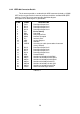
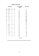
Description of the GPIB Signals is given below.
PIN NO. NAME DESCRIPTION
1 DIO 1 Data Input Output Line 1
2 DIO 2 Data Input Output Line 2
3 DIO 3 Data Input Output Line 3
4 DIO 4 Data Input Output Line 4
5 EOI End or Identify
6 DAV Data Valid
7 NRFD Not ready for Data
8 NDAC Not Data Accepted
9 IFC Interface Clear
10 SRQ Service Request
11 ATN Attention
12 SHIELD Screening on cable (connected to Instrument
Safety Ground).
13 DIO 5 Data Input Output Line 5
14 DIO 6 Data Input Output Line 6
15 DIO 7 Data Input Output Line 7
16 DIO 8 Data Input Output Line 8
17 REN Remote Enable
18 GND 6 Gnd wire of twisted pair with DAV.
19 GND 7 Gnd wire of twisted pair with NRFD.
20 GND 8 Gnd wire of twisted pair with NDAC.
21 GND 9 Gnd wire of twisted pair with IFC.
22 GND 10 Gnd wire of twisted pair with SRQ.
23 GND 11 Gnd wire of twisted pair with ATN.
24 LOGIC GND Instrument Logic Ground.
TABLE 6.1
29