
Instruction manual


i) Press the RESET button in the window and exit from CSPY.
j) Turn OFF the unit & remove JTAG connector. This will complete the software
installation for GPIB option.
7) Again turn the unit ON & confirm the polarity of the supplies on the supply connector
provided for GPIB option. (At 3 pin connector connected to J7 of SBC-IEB-0504A, Pin
no. 1 is + ve, pin no. 2 is common and pin no. 3 is –Ve supply. The Voltage is approxi-
mately 10 Volts. At 4-pin connector connected to J5 of SBC-IEB-0504A, Pin no. 1 is +
ve and pin no. 4 is –Ve supply. The Voltage is approximately 10 Volts. ) Turn The unit
OFF.
8) For the GPIB option, there is provision of the jumper links on the VSP-DPM-CONT-
1204D for the hardware correction. Remove JP6 near IC U4 (This will disconnect the
+5V supply presently sourced from display board).
9) Remove jumpers JP2, JP3, JP4 & JP5. (This will isolate CV, CC, OVP and OT sig-
nals from connector J4)
10) Install jumper JP1 for GPIB mode. (By default, this jumper is open and need to install
in GPIB option).
11) Mount the INSTR-TO-GPIB-1188 pcb on the location 12 with the rear 2 screws.
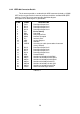
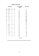
12) Before mounting the SBC-IEB-0504A pcb make sure that FRC connectors provided
for interconnection are placed according to following table. Also place the insulation
paper below the pcb & route the cables below the pcb.
13)
Sr. No. Cable Type Connector No. on To
SBC-IEB-0504A
PCB
01 26 Pin FRC (Long) J6 J1 of INSTR-TO-GPIB-1188
02 26 Pin FRC J8 J1 of VSP-POT-IMON-0604A
(Location no. 19)
03 16 Pin FRC J2 J7 of VSP-DPM-CONT-1204D
04 16 Pin FRC J3 J5 of VSP-DPM-CONT-1204D
05 3 Pin SIL J7 Existing in the unit wired for GPIB
option.
06 4 Pin SIL J5 Existing in the unit wired for GPIB
option.
14) Please make sure that the pin no. 1 of all the connectors are properly installed to the
pin no 1 of destination connector.
15) Now the unit is set for GPIB option. Turn the unit ON with ‘Line’ switch. Display will
show the blank digits for a while and after a small delay it is ready to work in the
LOCAL mode of operation.
16) Check the GPIB interface with the standard available PCI-GPIB interface software.
Turn the unit OFF.
17)Now reconnect the earth connection to the top cover & reinstall the top cover. This will
complete the installation of GPIB interface.
32
f) Compile the project.
g) Connect line input to the unit. Keep the front panel output ON/OFF switch in
OFF position. Turn the unit on with the input ‘Line’ switch.
h) Run CSPY to download program in flash memory of the controller.