
Instruction manual


3.3 Input Power Requirements
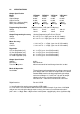
The Model VSP power supply is configured at the factory to operate from 95-264
VAC at 47-63 Hz power line.
3.4 System Configuration
The Model VSP series power supply comes in ready to use fashion and does not
require any configuration in the field for operation in the local mode. For analog interface
refer to the connector details for the connections.
3.5 Installation
1. AC Input Power Connection
Connect a 3-pin power mains cord to the available line supply. Before connect-
ing line ensure the following:
a) The available line supply is compatible to your unit.
b) The available line supply point is capable of supplying the maximum peak current
and power.
2. Load Connections
Refer fig.3.1A for load connection in local and remote sensing mode, the unit has
5mm brass studs on the rear panel for load connections for model up to 30A. The bus
bar is provided from 30A onwards.
For remote sensing and the current sharing option it is provided with separate 6
way terminal block. This is required if your load is far away & regulation needs to be
maintained at load terminals.
An output cable should be able to handle the full load current and maximum
voltage and power under worst case conditions of temperature, humidity, mechani-
cal abuse, and effects of long term aging.
3.
Analog Interface Connections
A 25 pin D type connector & DIP switch is provided for remote analog interface
to the unit. There is 8 pin DIP switch associated with the function of analog interface.
Refer to section 4.3.5 of chapter 4 for switch settings.
4. Turn-On
Switch the POWER ON switch to the ON position. Soon the DPM will be turned
on & the output voltage & current are displayed, if output on-off switch is in ON position.
Voltmeter should display the voltage set by voltage control.
Check the current meter. It must show zero (very low) current under no load. If
not then please switch off the unit and call the service personnel.
For details of TURN ON CHECK refer section 4.5 of CHAPTER 4.
7