AURORA SERIES PORTABLE RADIO User’s Manual Aurora User’s Manual 1
BK Radio
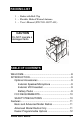
PACKING LIST 1 – Radio with Belt Clip 1 – Flexible, Helical-Wound Antenna 1 – User’s Manual (P/N 7001-30927-401) CAUTION Do NOT operate a damaged radio. ! ra o r Au TABLE OF CONTENTS WELCOME ......................................................................8 INTRODUCTION .............................................................9 Optional Accessories .................................................9 External Speaker/Microphone ..............................9 External VOX Headset ..................
TABLE OF CONTENTS Before Using Your Radio ...............................................13 Battery Installation and Removal .............................13 Antenna Installation and Removal ...........................14 Radio Views ..................................................................15 Aurora Radio Controls ..................................................16 Front View ................................................................16 Display ..................................................
TABLE OF CONTENTS Built-in Features ............................................................27 Audio ........................................................................27 Audio Options ..........................................................28 Battery-Saver Feature .............................................29 VOX Operation ........................................................29 Channel Selector .....................................................30 HI/LOW Transmit Power ...................
TABLE OF CONTENTS Scan Operation .......................................................43 Talkback Scan ....................................................43 Scan All Groups .................................................44 Change the Scan List .........................................44 Scanning Options ...............................................44 Scan Delay .........................................................44 Talk Around ........................................................
TABLE OF CONTENTS Originating a Call .....................................................58 Frequently Called Numbers and Call Paging .....59 Radio Paging ......................................................61 Flex Mode ................................................................61 Keypad and Channel Selector Lock ........................61 Busy Channel Lockout ..................................................62 Battery Power ................................................................
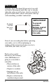
WELCOME Statistics show that about 80 percent of you will not look at this manual until after you’ve already taken the radio out of the box, tried to assemble it, played around with it, and at some point came up with something you didn’t understand. IMPORTANT So much for this box over here. To prevent possible damage, read all instructions before operating this radio.
INTRODUCTION Congratulations, you now own a BK Radio Aurora Series Flex•Mode™ Radio! This synthesized portable radio uses a microprocessor core to give you features and performance previously unavailable in a hand-held two-way radio. The Aurora radio has been designed to meet the tough requirements of today’s communications environment.
Battery Charger The optional battery charger (LAA 0337) has a dual well. One well is fast-charge, and the other is trickle-charge. Carry Case To give your radio more protection, you can order the optional carry case (LAA 0437). FCC REQUIREMENTS Your radio must be properly licensed by the Federal Communications Commission prior to use. Your BK Radio dealer can assist you in meeting these requirements. Your dealer will program each radio with your authorized frequencies, signaling codes, etc.
FEATURES All Aurora radios have features that are programmed into both the basic and the advanced models, except for scanning features, which are only available in the advanced model. Below is a list of features that are standard to all Aurora radio models, as well as those features that must be programmed by your dealer.
DEALER PROGRAMMABLE OPTIONS 12 • Five-tone ANI encode/decode • Two-tone sequential decode • Radio Paging: ANI (two-tone, five-tone, DTMF) with frequently called number memory • VOX (Voice-Operated Transmissions) • Internal options board activation • Keyless front panel radio parameter programming • Man Down (requires optional factory-installed tilt switch) • Radio stun feature BK Radio
BEFORE USING YOUR RADIO BATTERY INSTALLATION AND REMOVAL Installing the Battery The battery for the Aurora radio is connected on the back side of the radio. To install the battery, follow the steps below: 1. With the radio in one hand and the battery in the other hand, face the backside of the radio and the inner side of the battery toward each other. Side View Bottom Tabs Locking Tabs Rear View 2.
Removing the Battery WARNING: Explosion Hazard Do not dispose a battery pack into a fire. To avoid explosion, intrinsically safe radios designed for use in hazardous environments MUST use replacement batteries approved by Factory Mutual. To remove the battery, press down on the locking tabs and reverse the order for installing the battery. Antenna Installation and Removal Before using your Aurora radio, you need to install the antenna.
RADIO VIEWS Speaker Battery Battery Tab Aurora Microphone LED Display Belt Clip Keypad Battery Recharge Terminals Figure 3.
AURORA RADIO CONTROLS FRONT VIEW Display The Aurora advanced model radios have a front panel display that consists of status icons and an alphanumeric display of channel information and radio status. If you select the alpha display mode, the display will show the preprogrammed alphanumeric channel identifier. If you switch to channel or frequency display modes, the LCD displays either the channel number or the channel frequency information. In all cases, the radio status indicators (icons) are shown.
FRONT VIEW (continued) Backlight The Aurora radio display can be backlit, and your dealer programmed one of the following options for your radio: 1. Backlight on whenever you press a key (1–6-second auto timeout) 2. Backlight on whenever a signal is received and the audio is sent to the speaker (1–6-second auto timeout starting at carrier drop) 3.
TOP VIEW Status Indicator A dual color LED indicates the transmit mode, active receive carrier, priority sampling, low battery, cloning, and radio error conditions in the Aurora radio. Table 2.
TOP VIEW On/Off Volume Squelch Antenna Connector Channel Selector 3-Position Toggle Switch* Status LED Scan Mode** *Three-Position Toggle Switch (Factory Default) 1 Channel frequency 2 Channel label 3 Group number, channel number, and bandwidth **Programmable Red Switch Factory Default — Scan Programmable to — Emergency Figure 4.
Programmable Three-Position Switch The three-position switch on top of the radio is programmed by the dealer for features you can select in a variety of configurations. The default configuration is shown in Table 3 below: Table 3.
SIDE VIEWS Programmable Switches PTT Switch Use the PTT Switch to key-up the radio’s transmitter. At times, activating the PTT switch will not allow transmitter operation, such as when channels have active carriers with busy channel lockout is programmed or if no transmit frequency was programmed for the displayed channel. Programmable Softkey Buttons PTT The three softkey buttons on the side of the radio are programmed by your dealer to give you the radio features you want.
Options Connector The Aurora radio has a sealed options connector on the side of the radio (opposite the softkeys and the PTT switch) that facilitates: • Programming the radio for dealers • Using the RF antenna port Options Connector (without cover) • Using external transmit carrier modulation sources • Outputting data present on receive carriers • Giving access to external audio, including the microphone and earphone, as well as the necessary control line to switch audio from internal to external sources
BASIC OPERATION RECEIVE On/Off Volume Squelch 1. Turn power on. Turn the volume knob clockwise. The radio is operational when you hear the beep. The display, if installed, shows the current channel, frequency, or alpha characters depending on the position of the three-position switch on top of the radio. See Table 5. Table 5.
TRANSMIT Follow these steps to transmit: PTT 1. Press the PTT switch. When the transmitter is on, the red transmit indicator glows and the transmit icon [ ] appears in the display. 2. Talk in a normal voice with the microphone 1–2 inches from your mouth. 3. Release the PTT switch to stop transmitting. Aurora Microphone Channel 1 If the transmit status indicator does not glow red when you press the PTT switch, the battery pack may need to be charged.
CODE GUARD OPERATION Code GuardTM (sometimes called tone code) allows one radio or group of radios to be selectively called within a system. If the radio has been programmed with Code Guard, use the following receive and transmit instructions: CODE GUARD RECEIVE 1. Turn power on by turning the volume knob clockwise. 2. Select a Code Guard channel by turning the channel selector knob. Code Guard . . . ... ... ... ... ... ... ... Channel 1 Monitor Mode Channel 1 Code Guard/ Tone Mode 3.
CODE GUARD TRANSMIT Code Guard . . . ... ... ... ... ... ... ... ... ... ... PTT 1. Turn on Code Guard mode by pushing the gray button on the side of the radio, which is the factory default for toggling Code Guard on or off. If Code Guard is not assigned to a soft switch, you can also push one of the menu select buttons [ or ]until Monitor Mode is displayed, and then push [E]nter to toggle tone mode. Push [H]ome for normal display. 2. Listen to the Code Guard channel before transmitting.
BUILT-IN FEATURES The BK Radio Aurora radio is based on a microprocessor core that allows extra features and operational characteristics to be programmed into your radio. Your dealer can help define the best operational settings for your system and program them into the radio. AUDIO Beeps, Boops, and Warbles You can program your Aurora radio through the function menu so that the radio can make five different sounds to notify you of different radio functions: Beeps The beep is a tone of 1560 Hz.
Boop-Beep The boop-beep is a short duration tone of 780 Hz followed by a short duration tone of 1560 Hz. You will hear a boop-beep: • When you toggle a radio function ON with a softkey or the three-position switch • When you switch to scanning from manual mode • When you switch to tone mode from monitor mode Beep-Boop The beep-boop sound is a short duration tone of 1560 Hz followed by a short duration tone of 780 Hz.
BATTERY-SAVER FEATURE The battery-saver feature can be programmed by your dealer. This function temporarily powers down the hardware when the channel is not busy. VOX OPERATION Vox Operation is a special option that can be programmed on or off at the factory. You can use the VOX operation feature with an optional headset that can be connected to the radio via the options connector.
Status Indicator After 1 second, the radio will automatically start adjusting the VOX trigger sensitivity value. The radio cycles through the 16 available trigger values, starting at the least sensitive value and incrementing to the most sensitive value. Then the cycle wraps around, and the radio repeats the cycle as long as you keep pressing the softkey. 4. When the status indicator LED on the radio turns red, immediately release the VOX softkey. The VOX trigger sensitivity value has been reached.
HI/LOW TRANSMIT POWER Each channel in the radio can be individually programmed to always transmit in low-power or high-power mode, regardless of the position of the radio’s switches (or the function menu setting). Once a radio channel is programmed for low power, you will not be able to change this setting to high power. If a channel has been set to high power at the factory, the dealer can change the power setting to a softkey or the three-position switch.
FUNCTION MENU Any functions not assigned to a side button or the three-position toggle switch can be enabled/disabled with or on the keypad. You can use the function menu as follows: 1. Press menu. or to display the function 2. Use the or keys to move from one function to the next forward or backward. You will hear a beep with each key press. If you press an invalid key, however, you will hear a boop. 3. Press [H]ome to exit the function menu.
You can change the attributes of the following functions by pressing keys as described below: Backlite 1. Press [E]nter to start the timeout value to flash. 2. Press [E]nter. The existing number will flash. 3. Press [0]–[6] to set the time to off (0) or for 1-6 seconds. 4. Press or to change the timeout value by 0.1 second. 5. Press the [E]nter key to exit the backlite editing mode. Press [H]ome to exit function menu.
3. Press the [H]ome key twice quickly to delete the number from the list. 4. Press the [H]ome key twice slowly to exit the function menu. Each time you press [E]nter, the number type is toggled between DTMF and 5 Tone. The radio then displays the current frequently called number. Selecting and Activating Frequently Called “Phone List” Numbers 1. To see your list of frequently called phone list numbers, press [E]nter when the list is displayed to choose a frequently called number.
Editing Frequently Called Numbers To edit a frequently called number, press [E]nter when the display shows the attribute for the currently selected number. You can use the following valid keys to edit a frequently called number attribute: • [H]ome. Clears the number or alpha. Type attribute has no effect. • . In edit mode, the down arrow key shifts the cursor to the right. • . In edit mode, the up arrow key shifts the cursor to the left. • Any key.
DTMF ENCODING Keypad-equipped radios can be programmed to enable DTMF (Dual Tone Multiple Frequency) number dialing sequences. . . . ... ... ... ... ... ... ... ... ... ... ... ... ... ... ... ... ... To send DTMF tones: 1. Press [H]ome to return to the main display if your radio is in the DTMF function menu. PTT 2. Press and hold the PTT switch. 3. Press any key on the keypad (except arrow keys). You will hear a sidetone (sounds like the tones you hear when dialing a telephone).
TRANSMIT TIME-OUT TIMER The transmit timeout timer is dealer-programmable. The length of the time out is the maximum amount of time the radio transmits after you press the PTT button. If you are still talking past the timeout timer, the radio will stop transmitting and you will hear a continuous boop error message until you stop pressing PTT. Your dealer can program a group’s transmit timeout timer from 0 [no time out] to 4 minutes in 15-second increments.
EMERGENCY GROUP/CHANNEL The emergency sequence is always transmitted on the emergency group/ channel regardless of the current function mode and channel. Once the emergency sequence is started, and up to the time it is acknowledged, the radio will stay on the emergency group channel, although the channel knob and group change function are still active.
Three seconds before starting the man-down emergency sequence, you will hear the man-down audible warning (a fast-rate warbling lasting 3 seconds). If you put the radio upright during the man-down audible warning, the radio stops the emergency sequence. If the radio stays tilted for the duration of the man-down audible warning, the emergency sequence is immediately activated.
OPERATING MODES MANUAL MODE Channel Selector Knob The Aurora radio can operate in manual mode, which ties the receive and transmit frequencies to the channel you select with the channel selection knob (within the currently selected channel group). For advanced model radios, you can select manual mode from the function menu if manual/scan or talk around is not assigned to the three-position switch. 000.0000 000.0000 12 Reassigned channel number 000.
For advanced radios in manual mode, you can use the keypad for the following six functions: 1. Reassign the variable guard. Press number keys [0] through [9] 2. Enter group change mode: Press the [H]ome key. Then press or to change the group number. 3. Add or delete channels from the scan list. Press the [E]nter key. R114.8 T107.2 Code Guard Assignment Channel 1 Keypad Locked 4. Review a channel’s Code Guard assignment. Press and hold the [*] key. 5. Enter the function menu. Press either or . 6.
Channels assigned with receive selective calling signals and set for busy-channel lockout cannot be monitored if the radio is in monitor mode. Channels that are programmed with no tone are not affected if the radio is placed in either monitor mode or tone mode. You will hear a beep/boop sound when toggling between tone and monitor modes. For advanced model radios, the tone mode icon [ ] is illuminated when you put the radio in tone mode, and turned off when you put the radio in monitor mode.
Variable Guard Advanced model radios have a variable guard feature that lets you reassign the Code Guard of one channel to another channel within a group. You can use this feature if your dealer programs your radio to let you: • Use the variable guard reassignment per group option. • Decide if you want the Code Guard reassignment to apply to both the receive and transmit channel frequencies or to just the transmit frequency.
When you are scanning with both scan all and priority enabled, the priority channel you are sampling or transmitting on will occur within the group that the radio was in when you started the scan-all-groups scanning. P000.0000 When you change the radio from manual to scan mode with scan all enabled and then later you switch back from scan to manual mode, the radio returns back to the group it was in when you started scan mode.
After the scan delay time, if the radio is not in priority channel operation, the radio transmits on the channel indicated by the channel selector knob within the group that is being scanned (see priority channel operation for radio scanning operation while priority mode is enabled on page 48). Talkback Scan Your radio has a talkback feature (sometimes called talk around) that lets you transmit on the channel you just received a signal on under the following conditions: 1. You stay on the same channel . .
Scan in Tone Mode The Aurora radio is capable of scanning and receiving channels with CTCSS tone guards or CDCSS Code Guards. When you are on a scanned channel with a carrier present, the radio will try to decode the proper tone. If it does, you will hear the message. 000.0000 If the channel has a carrier present, but the tone is incorrect, the radio skips that channel (removes it from the scan list) for a period of 3 seconds, and then adds it back to the scan list.
Channel Scan Delete/Add Squelch Knob With the Aurora radio, you can delete and add channels to the scan list in each group if this feature is programmed in your radio. To add or delete a channel from the scan list: 1. Use the function menu to put the radio in scan mode on an active receive carrier. 2. Tune your radio to the frequency of a receive channel frequency, or open the squelch to the channel being added or deleted. 3. Press [E]nter to toggle between deleting or adding a channel to the scan list.
Priority Scan Priority Scan with Code Guard Priority scan can be used along with Code Guard when: Code Guard . . . ... ... ... ... ... ... ... ... ... ... ... ... ... ... ... ... ... • You move the three-position switch into position 1, which displays the channel frequency.
Orange Status Indicator P 000.0000 Priority Channel When you turn on priority mode by pressing the middle button on the side of the radio, you will see the status indicator flash orange, which indicates an actual priority channel sampling. For advanced model radios, the priority channel of a group is indicated by a “P” [a small “p” when deleted from the scan list] on the left side of the radio display. P 000.0000 Priority Channel deleted from scan list Table 6.
Priority Delay Your dealer can set the priority delay time for 0 to 5 seconds in 0.5-second increments. This time delay is the time from when you lose a carrier for the priority channel and the time the radio stays tuned to the receive frequency of the priority channel. This is also the time you have to transmit on the transmit frequency of the priority channel. Priority Receiving Priority channel receive sampling only occurs while the radio is not transmitting.
RECEIVE MODE Groups A channel group can have up to 16 tunable channels (both receive and transmit frequencies). The basic Aurora radio has one group, and the advanced Aurora (with keyboard and display) has from 1 to 15 groups, depending on the computer programming. Although the maximum allowable channels per group is 16, any number less than that, down to one channel, can be programmable in a group. For advanced model radios, you enter groupchange mode by following these three steps: 1.
• [E]nter Exits the group change mode • [H]ome Displays the alpha label of the group The radio will remain in group change mode until you exit by pressing the [E]nter key. DISPLAY MODES You can select a display mode either with a softkey/three-position switch programmed to display functions, or with the function menu. If you use a softkey, each key you press selects the next display mode. The radio will keep cycling through the channel, frequency, and alpha modes.
FREQUENCY DISPLAY MODE If you own an Aurora radio with a display, you have the option of displaying the current group/channel frequency information as follows: P 000.0000 Priority Channel P 00000000 Character Positions 2–9 P 139 . 650 00 Character Positions 13–14 P 139.
ALPHA DISPLAY MODE If you have an Aurora radio with a display, you can select how the radio shows you the current group/channel alphanumeric information: d 000.
CHANNEL DISPLAY MODE If you have an Aurora radio with a display, you can select how the radio displays the current channel information: • Priority channel/deleted channel specifier (first display character position) P 000.
SELECTIVE CALLING Radio Paging Code Your dealer can program your radio to decode 2-tone, 5-tone and DTMF ANIs, and encode 5-tone and DTMF ANIs. Receiving a Call With the radio in receive mode, the squelch will only open when it receives an ANI code that is identical to its own ANI code. • 2-Tone Decoding The Aurora radio is capable of receiving and decoding 2-tone-sequential paging. Your dealer can program the tone frequencies to cover Motorola 1+1, Reach Two Tone, and GE Type 99 formats.
When you receive a 2-tone, 5-tone (except radio check and stun) or DTMF ANI paging code, you can hear a warbling ring. This ring sounds the same for 2-tone and DTMF pages, but the group and all-call pages each have a different warbling ring. Your radio will ring for 3 seconds when you receive a call. (See Receiving a Call, page 56). Sending a Call The Aurora radio can encode the ANI paging code for the Unit ID of a channel group. The 5-tone or DTMF code is assigned to the transmit frequency of a channel.
RADIO CHECK The Aurora radio has a radio check feature that is active whenever your radio is: • Programmed for receive-ANI paging • Tuned to a channel that has receiveANI assigned • Placed in tone mode When radio check is active, if your radio receives its radio check paging ANI, then it transmits with its unit ID paging ANI. If the transmit channel being transmitted is programmed for transmit ANI, then the unit ID goes out as specified by the transmit ANI protocol (DTMF or 5 Tone).
REMINDER: The number does not have to be keyed in each time you make a call unless you want to change the number or the radio has been turned off since the last call. 3. Press the PTT switch to enable the transmitter and the DTMF keypad. 4. While holding in the PTT switch, either press the desired DTMF keys and/or speak into the microphone of the radio. 5. After you finish talking, release the PTT switch to listen to any reply.
Call page or FCN sequences are transmitted after you 1. Select the CALL feature or one of the FCNs from the function menu 2. Press the PTT switch The page/FCN of your radio is transmitted on the appropriate channel depending on the manual/scan/priority mode of your radio and the carrier activity when you press the PTT switch. If the transmit channel has Transmit-ANI assigned, the leading/trailing/or both Transmit-ANIs are sent as normal. The radio uses either the DTMF or 5-Tone ANI assigned to the channel.
RADIO PAGING d Office 02 Channels with radio paging code signals are indicated in the display with the radio page icon [ ] regardless of whether channels, frequencies, or alphas are being displayed. When the radio is receiving signals and the radio page icon is illuminated, the receive frequency has a paging code assigned. If the radio is in monitor mode, the radio page icon will not be illuminated while receiving.
BUSY CHANNEL LOCKOUT The Aurora radio has a Busy Channel Lockout [BCL] feature that you can use to program individual channels. With the BCL feature, you can keep anyone from hearing a channel unless the correct Code Guard signal is received. With BCL set, the transmitter cannot transmit until the channel is free of activity. If the channel is active, the transmitter cannot transmit until a correct decode Code Guard is received. If the BCL transmit criteria is not met, you will hear a boop.
BATTERY POWER Battery Saver d Office 02 Low Battery Icon Low-battery indicator The Aurora radio has a battery-saver feature that your dealer can program on a per radio basis. If enabled, the radio performs the battery-saver function when receiving channels without receive-ANIs whenever in manual mode and priority operation is turned off. The battery-saver function cycles the power to the RF, audio, and CPU hardware, temporarily powering down the hardware when the channel is not busy.
power of the channel or the power setting you select. You will hear a low-battery audio beep once every 30 seconds. Once the radio shows the low-battery icon, even if the battery voltage goes above the threshold setting, the radio will remain in the low-battery condition until you replace the battery. Second Battery Threshold The Aurora radio has a second battery threshold level.
RADIO POWER-UP The Aurora radio performs a power-up initialization and self test. The initialization includes loading fixed factory and computer-programmed settings, as well as the configurations and modes you entered into the radio before you turned it off. During the initialization, the firmware version number of the radio is written to the first four bytes of the e2prom.
The stun feature is active if the radio is: • Factory-enabled for audible ANI paging • Tuned to a channel that is assigned a receive ANI • Placed in tone mode When the stun feature is active and the current group’s stun code is received, the radio transmits the unit ID of that channel. This mutes the radio audio and disables any further transmitting.
AURORA PROGRAMMED SWITCH SETTINGS Side Switch Settings (Factory Setting) A B C Switch A _____________(Code Guard; Tone/Monitor) Switch B _____________(Priority) Switch C _____________(Hi/Low Power) 3-Position Toggle Switch 1 ______________(Channel Frequency) 2 ______________(Channel Label) 3 ______________(Group, Channel, BW) Emergency Switch Setting ________________(Scan) Group Number ______ Receive Chan Frequency CG Group Label __________________ Transmit Frequency CG Label Band 1 2 3 4 5 6 7 8 9 10
PROGRAMMED SETTINGS FOR YOUR RADIO Group Number ______ Receive Chan Frequency CG Group Label __________________ Transmit Frequency CG Label Band 1 2 3 4 5 6 7 8 9 10 11 12 13 14 15 16 68 BK Radio
TROUBLESHOOTING GUIDE NOTE: Please perform the simple checks indicated for improper operation before returning the radio for service. TROUBLE CHECK No display, no sound Turn PWR/VOL control clockwise. Charge or replace batteries. Display OK, no sound Turn volume control setting clockwise. No reception (no stations heard) Check antenna connection. Move to a location closer to a station. Enter correct frequencies.
MAINTENANCE CAUTION: Do NOT tamper with the internal components. Damage to the equipment and/or improper operation could result. Service All adjustments affecting the transmitter power output, carrier frequency, or modulation MUST be performed by a qualified BK Radio electronics technician. Have the radio checked periodically by a qualified BK Radio electronics technician.
SPECIFICATIONS (Subject to change without notice) Aurora Radio Number of Channels Frequency Range Operational Bandwidth Channel Spacing Channel Increments Size with battery; (W x D x H inches) Weight with battery and antenna 16 240* 136–174 MHz 38 MHz 25/30 or 12.5/15 2.5 kHz 2.45 x 1.6 x 6.5 22.7 oz (0.64 kg) Power Requirements Battery Voltage 10V (9.6V) Current Drain Standby (w/ Battery Saver) 22 mA Standby (w/o Battery Saver) 56 mA Rated Audio 500 mW Transmit: 1 Watt 5 Watts 0.8 Amp 1.
SPECIFICATIONS (Cont.) 25/30 12.5/15 Sensitivity (12 dB SINAD) 0.25 µV 0.
DEFINITIONS AND ACRONYMS Alphanumeric ANI BCL Beep Boop BW CG Cloning Code Guard Detent DTMF DTMF Tones [E]nter FCN [H]ome LCD LED PRG PTT RTA RX SCN Squelch Time-Out Timer TX VOX Warble Aurora User’s Manual Both letters from the alphabet and numbers Automatic Number Identification Busy Channel Lockout A higher tone of 1560 Hz A lower tone of 780 Hz, “error tone” Band Width Code Guard The process of copying data from one radio, called “master,” to other radios, called “slaves” or “clones” A subaudible to
NOTES 74 BK Radio
Aurora User’s Manual 75
BK Radio 7505 Technology Drive West Melbourne, FL 32904 (800) 648-0947 Fax: (321) 984-0434 © Copyright 2000 BK Radio. All rights reserved.