MicroTREK HT two-wire guided microwave level transmitters Manufacturer: NIVELCO Process Control Co. H-1043 Budapest, Dugonics u. 11. Tel.: (36-1) 889-0100 Fax: (36-1) 889-0200 E-mail: sales@nivelco.com www.nivelco.com BKI 09 ATEX 0003X ♦ htk4014a0600p_01.
max. programmed value of the measuring distance of the application max. measuring range of the instrument the factory set maximum measuring distance of the instrument (Xm) factory set value of the min. measuring distance (dead zone) Xm GUIDED MICROWAVE LEVEL MEASUREMENT upper dead zone set higher than the pre-programmed DIST= measured distance programmed measuring range of the applications 2 / 80 ♦ BKI 09 ATEX 0003X ♦ htk4014a0600p_01.
CONTENTS 1. INTRODUCTION ............................................................................................. 5 2. ORDER CODE ................................................................................................ 6 3. TECHNICAL DATA......................................................................................... 7 3.1 Accessories ............................................................................................ 14 3.2 Safety regulations for the Ex approved units.........
/ 80 ♦ BKI 09 ATEX 0003X ♦ htk4014a0600p_01.
Thank you for choosing a NIVELCO instrument. We are sure that you will be satisfied throughout its use! 1. INTRODUCTION Application The MicroTREK 2-wire level gauge uses the Time Domain Reflectometry (TDR) measuring principle and two-wire technology for level measurement. It is designed for measuring the distance, level, volume of liquids, pastes, slurries and powder products. The device is applicable in tank, silo, rigid pipe, reaction vessel and level reference vessel.
2. ORDER CODE MicroTREK H TYPE Transmitter High temp. transmitter Transmitter + display High temp. transmitter + display - 4 - * 2-wire guided microwave level transmitter CODE PROBE / PROC. CONN.
3.
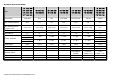
TECHNICAL DATA OF THE PROBES HK - - TYPE HA-- HL - - HR-- HS- - HN-- HT- - HD-- HB-- HV - - HP-- HZ- - HJ-- HU-- HE-- HC-- HW - - Denomination HH-- 4mm cable Rod Rod 8 mm cable 4mm twin cable Twin rod Coaxial Max. measuring distance 24 m 3m 6m 24 m 24 m 3m 6m Min. measuring distance εr = 80 / εr = 2.4 0.3 m / 0.4 m 0.3 m / 0.4 m 0.3 m / 0.4 m 0.3 m / 0.4 m 0.
TECHNICAL DATA OF THE COATED PROBES TYPE Denomination Max. measuring distance Min. measuring distance εr = 80 / εr = 2.4 Min. distance to objects Min. medium εr Process connection Probe material Nominal diameter of the probe Mass Fillet and weight coating material Weight dimensions Weight material Max. medium temp.
DIMENSIONS HTK- - HTA- - HTL- - HTR- - HTS- - HTN- - HTT- - HTD- - HTB- - HTV-- HTP- - HTZ- - HTJ- - HTU- - HTE- - HTC- - HTW- - 10 / 80 ♦ BKI 09 ATEX 0003X ♦ htk4014a0600p_01.
HTF- - HTG- - HTX- - HTY- - HTM- - HTQ- - HTI- - BKI 09 ATEX 0003X ♦ htk4014a0600p_01.
1 2 3 4 5 6 7 8 9 10 11 12 13 12 / 80 ♦ BKI 09 ATEX 0003X ♦ htk4014a0600p_01.doc Housing Cable gland High temp.
Nameplate 1 TYPE CODE 2 Serial number 3 Manufacturing date 4 Ambient temperature 5 Ex marking 6 EC-type certificate 7 AS ORDER CODE Serial number - 30 OC … + 60 OC AS TABLE Ci<10nF Li<10µH Ui<30V Ii<150mA Pi<1W 8 Ingress protection Ex marking H_X-_ _ _-8 3 Process Control Co. H-1043 Budapest, Dugonics u. 11.
3.1 ACCESSORIES • • • Certificate of Warranty Installation and Programming Manual Declaration of Conformity • • • PCStar2 software CD 2 pcs M20x1.5 cable gland SAP-300 display module (option) 3.2 SAFETY REGULATIONS FOR THE EX APPROVED UNITS The level transmitter must be operated in intrinsically safe circuit only. The metal enclosure of the unit must be connected to the EP circuit. 3.3 MAINTENANCE AND REPAIR MicroTREK does not require maintenance on a regular basis.
4. MECHANICAL INSTALLATION 4.1 HANDLING AND STORAGE The device will weigh between approximately 3 kg or 7 lb and 12 kg or 25 lb. Carry using both hands to lift the device carefully by the converter housing. If necessary, use lifting gear. No attempt should be made to lift the instrument by its probe. Caution: The probe is a critical gauge component. Do not damage - Handle with care! BKI 09 ATEX 0003X ♦ htk4014a0600p_01.
Avoiding blows - avoid hard blows, jolts, impacts, etc. Caution: fragile electronics Avoid bending (single rod and coaxial probes) - Support the probe to avoid bending. 16 / 80 ♦ BKI 09 ATEX 0003X ♦ htk4014a0600p_01.
Avoid cable kinks and fraying Do not coil the cable less than 400 mm or 16 “ in diameter. Cable kinks or fraying will cause measurement errors. 400mm minimum Storage temperature +80°C -40°C BKI 09 ATEX 0003X ♦ htk4014a0600p_01.
4.2 MOUNTING ON THE TANK 4.2.1 INSTALLATION INSTRUCTIONS: GENERAL NOTES Prior the installation some consideration is to be made regarding tank fittings and tank shape. Nozzle position in relation to the tank walls and other objects inside the tanks (Warning: this free area will depend on the probe type selected: refer to later on in this section) type of tank roof, i.e. floating, concrete, integral, etc; and base, i.e. conical, etc.
Nozzles penetrating into tank Caution: Do not use nozzles that penetrate into the tank. This will disturb the emitted pulse. Installation of two devices If two devices are to be used on the same tank, these should be mounted at a distance of at least 2 m or 6.5 ft away from each other. If not, interferences from the electromagnetic (EM) fields generated by both instruments may cause measurement errors. Coaxial probes: the outer shell of the probe contains the EM field: no minimum distance required.
Process connection and entry pipe Install far from entry pipe or use a deflector plate Caution: Do not put the nozzle close to the entry pipe. medium Pouring the product directly onto the probe will give false readings. Install deflector plate if impossible to distance gauge from entry pipe. Stilling wells Tanks with floating roofs for petrochemical applications: Use a stilling well. 1 2 3 4 5 6 20 / 80 ♦ BKI 09 ATEX 0003X ♦ htk4014a0600p_01.
Probes: entanglement, straightness and tank bottom clearance Cable probes must be straight once inserted into the tank. They must also be far from other objects (e.g. mixers) to avoid entanglement. In order to maintain the gauge’s operating characteristics, it is recommended to avoid touching the tank bottom with the counterweights (for cable probes) or probe end (other types).
Agitator in the tank 1 2 3 4 5 6 Agitator Support beam perpendicular to the pulse direction Abrupt changes in tank cross section Heating tubes Alternative solution: reference chamber - electromagnetic field is within chamber Gauge electromagnetic field : Any intruding metallic object will be detected in this zone if perpendicular to the emitted pulse direction. Do not fit the gauge near to these objects.
Fastening the probe to the tank bottom Flexible probes can be fastened with a chuck (ring), turnbuckle or similar fastening device to the tank bottom Shortening cable probes If required, the cable probe can be shortened, but this applies only when used in liquids. Procedure 1 Detach socket set screw M6x10 (ISO 4026) with 5 mm Allen (hexagon) key (ISO 2936). 2 Pull cable out of counterweight and shorten to required length using cable cutters to prevent the cable wires and strands from splaying out.
4.2.2 SPECIFIC INSTALLATION INSTRUCTIONS: GAUGE - SOLID APPLICATIONS FALSE READINGS: 1 24 / 80 ♦ BKI 09 ATEX 0003X ♦ htk4014a0600p_01.
Conical silo nozzles, false readings and traction on the cable probes 2 High traction forces: We recommend that the probe should not be anchored to avoid excessive traction loads on the cable. 3 Bending and traction: Position the connection on the roof at ½ radius of the tank and with minimum nozzle height. This will avoid damage due to bending and traction during emptying.
4.3 WIRING Wiring in non-Ex environment 1 2 3 4 5 6 Connection to the EP network (grounding). Screw type terminal (EP) on the housing max. cable cross-section: 4 mm². The housing of the MicroTREK must be grounded. Grounding resistance R < 1 Ohm The shielding of the signal cable should be grounded at the control room. Avoid coupling of electromagnetic noises place the singnal cable away from power-current cables. 26 / 80 ♦ BKI 09 ATEX 0003X ♦ htk4014a0600p_01.
Electrostatic discharge (E.S.D.) MicroTREK 2-wire non-Ex and Ex gauge electronics are shielded up to 4 kV against E.S.D. Note: E.S.D. cannot be solved by MicroTREK 2-wire E.S.D. protection. It is the customer’s responsibility to avoid E.S.D. by grounding the tank, product and probe installation. DANGER OF INJURY 1 The probe may receive an electrostatic discharge during operation; earth the probe by pushing it against tank wall with a suitably isolated tool just before touching it to avoid receiving a shock.
Non-hazardous-duty version US MikroTREK 2 vezetékes = mA RA HART 4 ...
Hazardous-duty version Connect the wires of the current loop to terminals 2 and 3 (any polarity). The intrinsically safe certified device may only be used in conjunction with an other intrinsically safe certified equipment. All the allowed electrical safety data indicated on the nameplate must be observed. An ’Ex’ repeater power supply unit must be used. For calculation of the supply voltage the same applies as for the standard non-’Ex’ version.
4.3.1 BUS ( HART®) COMMUNICATION Microtrek has two output options: Current out. and HART®, Passive, HART® protocol ’Ex ia’ current out. and HART® Intrinsically safe passive, HART® protocol In accordance with the Rosemount Standard, HART® communication can be used with a MicroTREK 2-wire. It is used as a point-to-point connection between the MicroTREK 2-wire as slave and the HART® master. converter PCSTAR” or HART specific software and operating devices 30 / 80 ♦ BKI 09 ATEX 0003X ♦ htk4014a0600p_01.
4.4 POWER-ON AND START-UP The MicroTREK 2-wire is pre-configured in accordance to customer order specifications and measurements can be made immediately. A start-up time of less than 60 seconds should be allowed once the unit is connected and the power is switched on. If the probe length has been shortened since delivery, please refer to section 3.3.1: Summary of User Functions, user function 1.1.6: Probe length to modify configured probe length. 4.
5. PROGRAMMING MicroTREK can be programmed in three (basic) ways. • Programming with PCSTAR 2 software • Programming with SAP-300 display unit • Programming with HART® Handheld (HHC) Communicator (For operating instruction see the User manual of the HHC) 5.1 PROGRAMMING WITH PCSTAR 2 SOFTWARE 5.1.1 PCSTAR 2: INSTALLATION AND EXECUTION. PCStar2 is a Windows software. It is used for programming the unit and displaying the measured variables.
Installing the program: execute the file "PCSTAR.EXE" and follow the instructions on the screen. Running the program: once the program is installed, execute the PCST2NT.EXE program. The screen shown below will be displayed. Define device interface: press F4 or left-click on “F4-Serial” at the bottom of the screen – to define the interface to which the device is to be connected. BKI 09 ATEX 0003X ♦ htk4014a0600p_01.
Serial port – The serial port allows the user to select a free serial port (COM 1 to 4) on the computer. MicroTREK Address – Type the “Address” that you have given a gauge (a value between 0 and 15) and press ENTER or OK. This will select the required device. If you are in a point to point network leave the box at its default value (-1). Device identifier – Device Identifier refers to the “Device number” given in User Function No. 1.4.4. Initial baud rate – Transmission rate of data.
After the connection has been established, the following screen is shown. This will show the current status of the tank. No further configuration should be necessary. The following functions are available on the screen and will be discussed further in section 8.
1.4.6 SUMMARY OF USER FUNCTIONS IN PCSTAR 2 (F2 – CONFIGURATION) The table below provides an overview of all parameters that can be set nt he configuration menu using F2 in PCSTAR2. Default values are in bold type nt he “Input Range” column. Function 1.0.0 Operation 1.1.0 Basic parameters 1.1.1 Tank height Input Range Enter 0 … 60 000 mm or 0 … 197 ft. As per order 1.1.2 Dead zone Warning: Critical Parameter 1.1.3 Time constant Fct.1.5.1 Enter a value Fct.1.5.1 (Detection delay) … probe length.
1.1.6 Probe length Minimum 100 mm Maximum 24 000 mm Ordered length + 100mm Set probe length + 100mm. This value should be modified when the probe has been replaced or shortened (cable probes). The output unit is set via Fct. 1.2.4 Length Unit. With an empty tank, using the function F11 nt he “Dynamic Configuration” menu an automatic search for the probe tip can be carried out to update the parameter. The value determines simultaneously: - the minimum value of the tank height, Fct. 1.1.
Function 1.2.0 Display 1.2.4 Length unit Input Range 1.2.5 Volume unit Select m³, l, US Gal, ft³, bbl, m³/h, ft³/h, kg, metric tonnes or tons US m³ • Select m, cm, mm, inch, nt h optional unit* Mm New unit (length) 1.2.5.1 Unit name 1.2.5.2 Unit fact. 4 ASCII characters Unit Minimum: > 0.0 Maximum: 100 000 1.0 38 / 80 ♦ BKI 09 ATEX 0003X ♦ htk4014a0600p_01.doc Description Unit for display of level and distance. *When “optional unit” selected, you get to the menu item Fct. 1.2.
Function 1.3.0 Current output Input Range 1.3.1 Current 1 item Select Off, Level, Distance, Volume* or Ullage volume* Level Select 4-20mA or 4-20mA + 22 mA on error. 4 – 20mA 1.3.2 Current 1 range Description Selection of the required function for the current output. This parameter defines the status which the current output assumes nt he event of a fault: 4-20 mA (last measured value held nt he event of a fault) 4-20 mA / E = 22 mA (is set to 22 mA nt he event of a fault). 1.3.3 Scale I1 min.
Function 1.4 User data 1.4.3 Checksum Input Range Read only 1.4.4 Tag number 00000 01 1.4.5 Serial number Read only 1.4.6 French command Read only number 1.4.6 German command Read only Number Option** (Descriptor) 1.4.9 Probe type Single rod, Twin rod, Single cable, Single cable + counterweight, Single cable without counterweight, Twin cable, Twin cable + counterweight, Coaxial, Special 1, Special 2 or Special 3 As per order 40 / 80 ♦ BKI 09 ATEX 0003X ♦ htk4014a0600p_01.
Function 1.5.0 Application 1.5.1. Detection delay Input Range Minimum value: 0mm Maximum value: Dead Zone As per order 1.6.0 Serial I/O 1.6.2 Address Addresses from 0 to 15 0 1.7.0 Volume table 1.7.2. Input table Select point 01 to 20, enter level and then volume values respectively. 0 (conversion table not created, volume measurement not possible) Description This function can be used to define an area directly below the flange in which interference reflections (e.g.
5.1.3 QUICK CONFIGURATION: CONFIGURATION EXAMPLES The minimum functions (fct.) to be configured for a simple measurement are listed below: Definition Functions PCSTAR 2 HART® 1.1.1 2.1.1.1 Tank Height 1.1.2 2.1.1.4 Dead zone 1.3.1 … 4 2.1.3.1 … 4 Current Output 1.7.0 2.1.7.0 Volume table* *For volume measurements Example procedures for each set of functions are given on the following pages.
Typical gauge used for quick configuration examples: Probe type: twin Ø4 mm or 0.15” cable probe Product measured: Water (dielectric constant, εr = 80) Tank height: (PCSTAR 2: Fct. 1.1.1, HART®: Fct. 2.1.1.1) 10000 mm Dead zone (PCSTAR 2: Fct. 1.1.2, HART®: Fct. 2.1.1.4) (see “ Technical data of the probes”) Probe length L2 (PCSTAR 2: Fct. 1.1.6HART®: Fct. 2.1.1.2) 9000 mm (do not modify unless advised to) Tank height: configuration of user menu PCSTAR 2 function 1.1.1 (HART® Fct. 2.1.1.
Example procedure 1 (using PCSTAR 2): to change true tank height (10000mm or 33 ft) to factory configured probe length, L2 (9000mm or 29½ ft) , and then save the new parameter. Refer to item 5 in the diagram above. Step 1 2 3 4 5 6 Action Press F2 to connect to the device Press F2 to enter configuration menu Click on the data set field for Fct. 1.1.1 Tank height Type in the new value Press the button “F6-Send to MicroTrek” for the MicroTREK 2-wire to immediately accept the new value.
Dead zone: configuration of user menu PCSTAR 2 function 1.1.2 (HART® Fct. 2.1.1.4) The top dead zone is the minimum measuring distance between the gauge flange facing (the reference point) and the product. The various probes for the MicroTREK 2-wire have differing top dead zones and these are given in section 5.2.3: Probe measurement limits. Why is configuration of the dead zone important? The gauge will not display measurements taken here - the reading is blocked on reaching this zone.
How to set an analogue current output scale User menu functions 1.3.1 to 1.3.4 This set of functions allows users to set up a scale. The minimum (4mA) and maximum (20mA) values of an analogue current output should ideally lie within the device’s active measuring zone, as the device will freeze when the signal is lost. Refer to the measurement limits table for each probe type in the introduction. Refer also to the start of section 3.3.3 for the advantages of changing tank height.
Setting up a volume table - (User menu PCSTAR 2 function 1.7.2 (HART® submenu 2.1.7)) To be able to measure the volume, a conversion table (strapping table) will need to be created using the PCSTAR 2 program or the HART® communicator. The strapping table assigns defined volumes to the various levels. In the case of non-symmetrical tanks, e.g. tanks with dished bottom, the accuracy of volumetric measurement will depend on the number of entered “level/volume pairs”.
Supplementary procedure for setting the 4 … 20 mA current to output volume readings (using PCSTAR 2) Step 1 2 3 4 5 6 Action Go to user function 1.3.1 ”Current 1 item” to select measurement function. Go to user function 1.3.2 ”Current 1 range” to set fault status Go to user function 1.3.3 “Scale I1 min” to enter volume value for the minimum output (4 mA) Go to user function 1.3.
5.2 PROGRAMMING WITH SAP-300 DISPLAY UNIT The main parameters of the Microtrek can be also set using the SAP-300 display unit. The default display shows the primary measured value (which the output current is calculated from). Besides the numerical display there is a bargraph on the right showing the value of the current output. Programming is hepled by a text-based menu. Navigation in the menu can be done with E / / / buttons. 5.2.
5.2.2 MICROTREK’S BEHAVIOUR IN MANUAL PROGRAMMING MODE After power-up MicroTREK shows the measured value on the SAP display. REMOTE MODE: If the instrument senses external HART communication it changes its display mode and shows a "REMOTE MODE" message in the bottom of the display. In this mode the measured values are refreshed according to the queries of the external HART master. If the HART master does not refresh the display will show the last measured values.
5.2.3 MANUAL PROGRAMMING The menu structure is similar to the PCStar2 parameter structure. Main menu BASIC SETUP Sub-menu PCSTAR 2 param. ID TANK HEIGHT DEAD ZONE CLOSE-END BLOCKING DAMPING TIME PROBE LENGTH 1.1.1 1.1.2 1.5.1 1.1.3 1.1.6 CURRENT MODE FAILURE CURRENT CURRENT MIN CURRENT MAX ERROR DELAY 1.3.1 1.3.2 1.3.3 1.3.4 1.3.
5.3 PROGRAMMING WITH HART® HANDHELD (HHC) COMMUNICATOR Display and configuration can also be carried out with a HART® communicator... Communicator layout 1 Two-pin jack for loop connectors 2 LCD 3 Function keys (F1 … F4) 4 Action keys UP On/off n/a Arrow LEFT DOWN RIGHT Arrow Arrow Arrow Other functions: LEFT Arrow: Previous menu key RIGHT Arrow: Select key Wiring, standard (non-Ex) Caution: Refer to the HHC manual for wiring instructions when in an explosive atmosphere.
Displaying readings Use the UP and DOWN arrows to move to the correct line and then select with the RIGHT Arrow. 1 HART Communicator 1 Offline 2 → Online 3 Frequency Device 4 Utility F1 F2 F3 Main menu 2 F4 3 F1 4 1 → 2 F1 SAVE HOME F2 F3 F4 Measurement & input & output functions menu Online 1 → 2 3 4 5 SAVE F2 F3 Online menu F4 ♥ 1 → Lvl 878.
Configuration: summary of user functions via HART® Communicator HC 275 (Version 1.00) Reset default values are in bold type in the “Input Range” column. Refer to the HART® HC275 Communicator operating instructions for further operating details. Function (Fct.) Input Range Description 1.0 PROCESS VAR. 1.1.0 MEASUREMENTS 1.1.1 LEVEL Level value 1.1.2 DISTANCE Distance value 1.1.3 VOLUME Volume value if a strapping table is programmed 1.1.
Function (Fct.) Input Range 2.0 CONFIG./TEST 2.1.0 OPERATION 2.1.1.0 BASIS PARAMETER 2.1.1.1 TANK HEIGHT Enter probe length to 60000 mm or 2362” As per order 2.1.1.2 PROBE LENGTH 2.1.1.3 TIME CONSTANT 2.1.1.4 DEAD ZONE Warning : Critical Parameter 2.1.1.5 SENSOR INFO 2.1.1.5.1 Sensor upper limit 2.1.1.5.2 Sensor lower limit 2.1.1.5.3 Sensor min. span 2.1.2.0 DISPLAY Description Tank height. The tank height is defined as the distance between the bottom of the tank and the lower flange surface.
Function (Fct.) 2.1.2.1 LENGTH 2.1.2.1.1 LENGTH UNIT Input Range Description Select m, cm, mm, inch, Ft, optional unit mm 2.1.2.1.2 DISPLAY FORMAT 0, 1, 2, 3, 4, 5, exponential format, auto Length unit of displayed value (level / distance). The optional unit allows the user to define a new unit (name and factor) see menu 2.1.2.1.3 Number of decimal places. Defines the displayed length values format (option of the HART® communicator H275). 2 2.1.2.1.3.0 DEFINE NEW UNIT 2.1.2.1.3.
Function (Fct.) Input Range 2.1.3.0 ANALOG OUTPUT 2.1.3.1 FUNCTION I Select Level, Distance, Volume, Ullage Volume Level Description 2.1.3.2 Current output range 4 … 20 mA (1st choice). When the MicroTREK 2-wire is in error mode, the current output is frozen except if the second choice is selected and then the current output is fixed at 22 mA. This menu is available in case the range I menu is set to 4-20 mA with error 22 mA.
Function (Fct.) 2.1.4.0 USER DATA 2.1.4.1 TAG Input Range Description 00000 01 Tag number of device 2.1.4.2 SERIAL NUMBER Read only menu. Each device has its own serial number 2.1.4.3 2.1.4.5 FRENCH COMMISSION NUMBER GERMAN COMMISSION NUMBER RELEASE NUMBER 2.1.4.5 PROBE TYPE Read only menu. This number is factory set. Refer to this number in case of warranty or service claims. Read only menu. This number is factory set. Refer to this number in case of warranty or service claims. Read only menu.
Function (Fct.) 2.1.5.0 APPLICATION 2.1.5.1.0 THRESHOLD 2.1.5.1.1 LEV. PULSE AMP. Input Range Description Read only value. 2.1.5.1.2 LEV. PULSE GAIN Read only value. 2.1.5.1. THRESHOLD Enter a value from 50mV to 25000mV 500 mV G3 at 1000 mm Dynamic value. Amplitude of level pulse in millivolts. Dynamic value. Amplification of level pulse (gain 0, 1, 2, or 3). Threshold of the level pulse (in millivolts).
2.1.7.0 2.1.7.1 STRAP TABLE VOLUME UNIT 2.1.7.2 INPUT TABLE 2.1.7.3 DELETE TABLE Function (Fct.) 2.2.0 TESTS 2.2.1 TEST OUTPUT Select m3, l, US Gal, Ft3, bbl, M3/h, Ft3/h, kg, Metric Tons, US Tons Liter [l] 0 to 20 points 0 (i.e. no volume table) Unit for conversion values ("volume table"). The selected unit is used to define the strapping table values. This function defines the strapping table. The maximum number of points is 20. Each subsequent value must be greater than the previous one.
Function (Fct.) 5.0 HART® VARIABLES 5.1 MANUFACTURER Input Range Description Read only menu NIVELCO 5.2 MODEL Read only menu 5.3 FLD DEV REV Field device revision. Read only menu 1.0 5.4 SOFTWARE REV 1.0 5.5 HARDWARE REV 5.6 5.7 5.8 5.9 5.10 5.11 5.12 DEVICE ID MESSAGE DESCRIPTOR DATE NUM RESP PREAM TAG POLL ADDRESS 1.0 Software revision. Read only menu Hardware revision. Read only menu. Read only menu. The device ID is also the serial number of the device.
5.3.1 CHARACTERS AVAILABLE FOR ALPHA-NUMERICAL DATA FUNCTIONS IN PCSTAR2 AND ON THE HART® CONSOLE PCSTAR2 HART® console (HHC) @ H P A I Q B J R C K S D L T E M U F N V G O W Fct. 12.6.1: Unit name, Fct. 1.4.4: Device number, Fct. 1.4.8: Option Fct. 5.7 Message, Fct. 5.8 Descriptor, Fct. 5.11 Tag X Space ( 0 8 Y ! ) 1 9 Z “ * 2 : [ # + 3 ; \ $ ‘ 4 < ] % 5 = ^ & . 6 > _ ‘ / 7 ? 62 / 80 ♦ BKI 09 ATEX 0003X ♦ htk4014a0600p_01.
5.4 MICROTREK 2-WIRE T.D.R. METER CHARACTERISTICS This subsection explains: the four principle configurations for setting up a measurement scale and what the user should be aware of in each case; what happens when the tank is full or empty; what is the level threshold and how to modify it and what happens when level is measured when more than one product in the tank; The measurement scale: five possible configurations for analogue current output – with “Level” selected in PCSTAR 2 function 1.3.
The configurations described below are illustrated in the above diagram (1) The “current output” range is smaller than the max. possible measuring range (2) The “current output” range is equal to the measuring range: Scale min.: 4 mA (Fct. 1.3.3) = tank height – probe length + H Scale max.: 20 mA (Fct. 1.3.4) = tank height – dead zone (3) The “current output” range is greater than the measuring range: Scale min.: 4 mA (Fct. 1.3.3) = 0.0 Scale max.: 20 mA (Fct. 1.3.
5.4.1 GAUGE OPERATING LOGIC WHEN THE REFLECTION IS LOST The product reflection pulse is usually lost when the level is in the top dead zone or near the bottom of the tank. The diagram below shows the action taken by the gauge depending on where the last reflection was lost. Use PCSTAR 2 - F8-Marker display function to follow the measurement status of the gauge.
5.4.2 GAIN AND VOLTAGE AMPLITUDE As explained in the measuring principle in the introduction, the level of a product is converted from a return signal (the product reflection) received by the gauge: this signal has taken a certain amount of time to return to the gauge and it has a certain strength / size measured in milli-volts (dependant on the dielectric constant εr of the product).
Level measurement: Level pulse amplitude and threshold After connection to a power supply, the MicroTREK 2-wire will: 1. Measure reflection pulses in terms of voltage amplitude by cycling through a set of gains. 2. Identify the highest amplitude as being the product level. This screenshot of the PCSTAR 2 F7-Oscilloscope function while measuring a typical one product application identifies: 1 Initial pulse 2 Flange reflection (except coaxial probe) 3 Non-product reflection (e.g.
The level signal can be optimized by way of two factors: Amplification factor The amplitude of the signals is proportional to the dielectric constant εr of the product. At low amplitudes the signal should be amplified. The amplification factor is dependent on the dielectric constant εr and on the probe type. The device sets the gain automatically. The following factors apply to the set gain: Gain 0 1 2 3 Amplification factor 1.05 2.10 4.37 8.
1 Initial pulse 2 Flange reflection 3 Level signal 4 Interference signal 5 Threshold In the diagram above it can be seen that the level of the threshold is not constant: 400 mV at 1000 mm or 3.3 ft, and only 250 mV at 10000 mm or 33 ft. No attenuation is required at a probe length ≤ 3000 mm or 10 ft. The form of the threshold is dependent on attenuation and is automatically adjusted by the device over the measured length. Setting the level threshold If the level threshold is set too high, i.e.
5.4.3 TYPICAL SIGNAL TRENDS The following diagrams show characteristic signals that have been recorded with the oscilloscope function. Rod or cable probe with gain 1 Rod or cable probe with gain 2 Coaxial probe with gain 1 Coaxial probe with gain 2 The signal from coaxial probes does not include the flange reflection, due to the mechanical setup which does not produce any change in impedance at the flange.
5.4.4 AUTOMATIC ADJUSTMENT To maintain a sufficiently strong reflection signal, the gain is adjusted automatically. When the amplitude of the level reflection decreases, the gain will increase to compensate for the loss in signal amplitude. Gain and level threshold thus maintain the same proportion. At gain 3, the level signal 1 is located between a distance of 2000 and 4000 mm or 6.5 and 13 feet. 2 is the level threshold.
Procedure (example where the level measured is too low compared to true level): read off displayed peak amplitude using the oscilloscope function – F7 modify level threshold value Step 1 2 3 4 5 6 7 Action Execute PCSTAR 2. Press F2 to connect to gauge. Press F11 to open F11-Dynamic configuration window. The top of the window gives the distance, peak amplitude in volts and gain. The configured level threshold is listed under peak amplitude in mV. Click on the “Modify” box to activate the “Threshold” field.
5.4.5 LEVEL MEASUREMENT WHEN MORE THAN ONE PHASE OR LAYER IN THE TANK Level can be measured with more than one phase in the tank. This requires setting a parameter in the factory menu (Fct. 1.1.
Example application 2: level measurement when there are 2 liquids (oil/water) in the tank – using a correctly configured gauge With Factory Menu Fct. 1.1.3: Application Type set to 2 liquids, 1 level, the MicroTREK 2-wire will search for the first return signal higher than the control threshold. It will correctly measure the oil level (i.e. “level”). 1 Threshold 2 Level signal 3 Oil-water interface signal For further information, please contact your local NIVELCO Service Centre.
5.5 TROUBLESHOOTING Event Error messages “Tank full” status marker on*, reading frozen at max. or min. value “Tank empty” status marker on*, reading frozen at max. or min. value “Tank full” and “Level lost” status marker on*, reading frozen at max. or min. value Fault Action No fault. The level has reached (and possibly risen above) the top configured measurement limit and is either displaying the maximum (when measuring level) or minimum (when measuring distance) output. No fault.
“Flange not found” status marker on* “Delay out of limits” status marker on*, reading is frozen. “Negative voltage error”* “VC01 voltage error” * “VC02 voltage error” * “Reprogramming FPGA” * The signal converter has been Contact NIVELCO for the corrective procedure. incorrectly configured to measure with a cable or rod probe when it is equipped with a coaxial probe. This may be also due to installation on a long nozzle which has the effect of attenuating the flange pulse.
Event General operation Instrument is not accurate with a product that has a high dielectric constant. A constant offset is observed when taking measurements. The MicroTREK 2-wire indicates an incorrect level value. Fault Action Tank height is not correct. Instrument is not accurate when there are two or more phases in the tank. The instrument may be incorrectly configured for this type of application i.e. it is measuring the interface instead of the level.
Event Fault Electrical Connections and Communication Output Current Output value < 4 mA. No power supply Connection of the device is incorrect. Reads 22 mA. The value at the current output does not correspond to the value at the display (PC STAR 2 or HART® communicator). Data communication via the digital interface is not working. The MicroTREK 2-wire is in its start up phase, wait 50 seconds and try again. Action Check the power supply Check the connection between the device and the power supply.
5.6 APPENDIX 1 – SET-UP PARAMETERS OF MICROTREK H-400 SERIES IN MULTICONT CONTROLLER Remote program. 90 Basic setup Output setup Application Service Basic setup 91 Length unit Tank height Dead zone Close-end blocking Damping time Probe length Output setup 92 Current mode Current min. Current max.
htk4014a0600p_01.doc April, 2009 Nivelco reserves the right to change technical data without notice! 80 / 80 ♦ BKI 09 ATEX 0003X ♦ htk4014a0600p_01.