
Technical data


BKI 09 ATEX 0003X
htk4014a0600p_01.doc
41 / 80
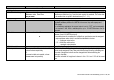
Function Input Range Description
1.5.0 Application
1.5.1. Detection delay
Minimum value: 0mm
Maximum value: Dead Zone
As per order
This function can be used to define an area directly below the flange in which
interference reflections (e.g. from the tank nozzle) are masked. This value has
to be smaller than or equal to the dead zone (Fct. 1.1.2.).
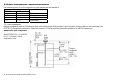
1.6.0 Serial I/O
For integrating into a signal network.
Standard hardware platform for HART® is the current loop with superposed
FSK signals.
For a multidrop application the current output is set to “OFF” and consequently
to a constant 4 mA. With a multidrop bus, up to 15 HART® devices can be
operated.
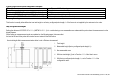
Addresses from 0 to 15 1.6.2 Address
0
With this function, every device connected to a bus is assigned an address
between 0 and 15 (HART® protocol).
If several devices are connected to a digital bus, each device must be assigned
a unique address under which it can then be identified in the bus.
0 = Analogue output active
1 - 15 = Multi-drop mode active,
analogue output inactive
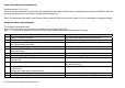
1.7.0 Volume table For calibrating the gauge for volume measurement.
Select point 01 to 20, enter level and then
volume values respectively.
1.7.2. Input table
0
(conversion table not created, volume
measurement not possible)
This function is used for setting up the strapping table (level/volume). Up to 20
points can be assigned. Every new point must be larger than the preceding one.
The units of length and volume can be changed later without affecting the
settings in the table.
The units selected for length and volume in fct.s 1.2.4 and 1.2.5 will be used
here.