
Technical data
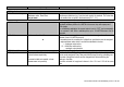


BKI 09 ATEX 0003X
htk4014a0600p_01.doc
43 / 80
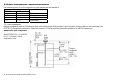
Typical gauge used for quick configuration examples:
Probe type: twin Ø4 mm or 0.15” cable probe
Product measured:
Water (dielectric constant,
r
= 80)
Tank height: (PCSTAR 2: Fct. 1.1.1, HART®: Fct. 2.1.1.1) 10000 mm
Dead zone (PCSTAR 2: Fct. 1.1.2, HART®: Fct. 2.1.1.4) (see “ Technical data of the probes”)
Probe length L
2
(PCSTAR 2: Fct. 1.1.6HART®: Fct. 2.1.1.2) 9000 mm (do not modify unless advised to)
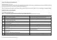
Tank height: configuration of user menu PCSTAR 2 function 1.1.1 (HART® Fct. 2.1.1.1)
This function is usually either defined as true tank height or as factory configured probe length, L
2
if the former is not supplied by the customer in the order.
Why change the tank height?
Setting the distance in PCSTAR 2 Fct 1.1.1 (HART® Fct. 2.1.1.1) to L
2
avoids having a non-measurable zone underneath the probe where the measurement on the
display freezes.
When setting up a measurement scale as explained on the following pages, this means that
the level at the end of the probe will be taken as zero instead of the tank bottom.
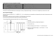
How tank height affects measurement when either Level or Distance is measured
1 Tank height
2 Measurable height (factory configured probe length, L
2
)
3 Non-measurable zone
4 With true tank height (1) set in Function 1.1.1 of the User’s menu
5 With factory-configured probe length, L
2
, set in Function 1.1.1 of the
configuration menu.