BL28NA-001 OEM Manual and User Guide BL28NA-001 OEM Manual and User Guide v 5 (to be used for certification) FCC ID: LHJ-BL28NA001 IC: 2807E-BL28NA001
BL28NA-001 OEM Manual and User Guide Terms and Acronyms • • • • • • • • • • • • • • • • • • • • • • • CDMA DCM DRX ES FDD GLONASS GNSS GPIO GSM HU HSIC LTE MP NAD OEM PCB PHY SIM TCU TDD TSP UMTS WCDMA Code Division Multiple Access Data Connectivity Module Discontinuous Reception Engineering Sample Frequency Division Duplex GLOBal’naya NAVigatsionnaya Sputnikovaya Sistema Global Navigation Satellite System General Purpose Input Output Global System for Mobile Head Unit High Speed Inter-Chip Long Term Evo
BL28NA-001 OEM Manual and User Guide BL28NA-001 Module The BL28NA-001 NAD is a proprietary modem module designed by Continental Automotive Systems, Inc. The modem will be integrated into Data Connectivity Modules (DCMs) or Head Units (HUs) designed and produced by Continental or by a 3rd party for use by automotive OEMs. DCMs will be installed into vehicles during the OEM’s factory assembly process and will not be accessible without use of special tools.
BL28NA-001 OEM Manual and User Guide ii. During manufacturing process of the integrated device, the module is soldered onto the pcb of the integrated device. iii. The integrated device must provide RF connectors to external antennas or RF traces to connect the BL28NA-001 modules to antennas inside the integrated device. The typical reference design for the RF trace layout, including pcb stack-up and trace length is described in Section 6 of this document. iv.
BL28NA-001 OEM Manual and User Guide 5 Instructions to OEMs: Continental must instruct the automotive OEM and provide them to include the following information into the car user’s manual (i.e. for the DCM): 1. End-users must be provided with transmitter/antenna installation requirements and operating conditions for satisfying RF exposure compliance: 2. A separate section should clearly state “FCC RF Exposure requirements:” 3. Required operating conditions for end users. 4.
BL28NA-001 OEM Manual and User Guide • GNSS_ANT The figure below shows the general breakout of the module: Figure 6-2: NAD Pin Breakout The LTE CAT4 NAD should be oriented on the main board to minimize the length of the PRIMARY_LTE antenna pin (LTE Ant1). This 50ohm line should be as short as possible to the external RF connector or internal antenna feed point. The RF traces from the NAD antenna pins on the main board can be stripline or microstrip.
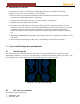
BL28NA-001 OEM Manual and User Guide The NAD has ground cleared out under the RF antenna routes as shown below: Figure 6-2: Antenna Pad Ground Cutout (Top View) For routing microstrip lines UNDERNEATH the NAD on layer 1, these ground cutouts internal to the NAD need to be accounted for in the stripline calculation. The internal GND height and dielectric constant of the NAD board are shown below: H = 19.3 mils (491 micron) Dielectric Constant = 4.
BL28NA-001 OEM Manual and User Guide Assume the main PCB above with a 6 layer stackup with ground cut away on layer 2 so the microstrip lines reference ground on layer 3. The dielectric thickness from L1 to L3 is 21.2 mils. Using an online impedance calculator, the line width under the NAD for a 50 ohm line is 16.9mils (433micron) shown below: BL Figure 6-4 The calculation for the microstrip line width outside the NAD is 37.
BL28NA-001 OEM Manual and User Guide ROUTING AND GND CUTS ON LAYER 2 WITH GND REFERENCE ON LAYER 3. THERE SHOULD BE NO ROUTING ON L2 AND SOLID GND ON L3 UNDERNEATH THESE ANTENNA LINE MICROSTRIP TRACES. The antenna traces need to routed STRAIGHT OUT OF THE NAD TO THE NEAREST NAD EDGE. The lines need to be tapered from 433micron to the 967micron width gradually but quickly. Figure 6-6 These line widths may vary depending on the stackup selected for the main board. 6.