LES301A LES301A-KIT LES301AE-KIT 1-Port 10/100 Device Server, RS-232/422/485, DB9 M Access a serial RS-232 or RS-422/485 device over a BLACK BOX 10- or 100-Mbps network. ® • Remotely monitor, manage, and control an industrial device in the field. • Easy to configure through a Web browser, serial console, Telnet™ or Windows® utility. Customer Support Information LES301A user manual Order toll-free in the U.S.: Call 877-877-BBOX (outside U.S.
Trademarks Used in this Manual Trademarks Used in this Manual Black Box and the Double Diamond logo are registered trademarks of BB Technologies, Inc. HP and OpenView are registered trademarks of Hewlett-Packard Development Company. Intel and Pentium are registered trademarks of Intel Corporation. MS-DOS, Microsoft, and Windows are registered trademarks of Microsoft Corporation. Any other trademarks mentioned in this manual are acknowleged to be the property of the trademark owners.
FCC and IC RFI Statements Federal Communications Commission and Industry Canada Radio Frequency Interference Statements This equipment generates, uses, and can radiate radio-frequency energy, and if not installed and used properly, that is, in strict accordance with the manufacturer’s instructions, may cause interference to radio communication.
NOM Statement Instrucciones de Seguridad (Normas Oficiales Mexicanas Electrical Safety Statement) 1. Todas las instrucciones de seguridad y operación deberán ser leídas antes de que el aparato eléctrico sea operado. 2. Las instrucciones de seguridad y operación deberán ser guardadas para referencia futura. 3. Todas las advertencias en el aparato eléctrico y en sus instrucciones de operación deben ser respetadas. 4. Todas las instrucciones de operación y uso deben ser seguidas. 5.
Table of Contents Chapter Page 1. Specifications........................................................................................................................................................................7 1.1 Hardware Specifications.................................................................................................................................................7 1.2 Software Specifications..........................................................................
Table of Contents Chapter Page 5. Using VirtualCOM................................................................................................................................................................ 37 5.1 Setup of a Virtual COM Driver....................................................................................................................................... 37 5.1.1 Pre-installation Requirements......................................................................
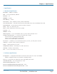
Chapter 1: Specifications 1. Specifications 1.1 Hardware Specifications Baud Rate — 1200 bps to 230 kbps CPU — 16-bit embedded CPU, 100 MHz Data Bits — 7, 8 EEPROM — 512 bytes Flash Memory — 512 KB Flow Control — None, Hardware CTS/RTS, Software X-ON/X-OFF Host Communication — IEEE 802.
Chapter 1: Specifications 1.3 DB9 Pin Assignments Table 1-1 shows the LES301A unit’s DB9 connector pin assignments. Table 1-1. DB9 connector pin assignments.
Chapter 1: Specifications 1.5 Power Terminal Block Connector F.G. VIN- VIN+ Figure 1-2. Terminal block signals. NOTE: VIN- and VIN+ can be reversed. 1.6 Buzzer/LED Message 1.6.1 Buzzer “^”: Beep twice “=”: Beep off Table 1-3. Buzzer message.
Chapter 1: Specifications 1.6.4 RUN LED Table 1-6. RUN LED. Page 10 Message Description LED on Jumper JP1 Pin 1 and Pin 2 are short; this disables AP firmware in flash memory LED is blinking at the rate once every 0.5 sec AP firmware is running 724-746-5500 | blackbox.
Chapter 2: Overview 2. Overview 2.1 Introduction The LES301A Ethernet Serial Server is a gateway between Ethernet (TCP/IP) and RS-232 or RS-485/RS-422 communications. The information transmitted by the LES301A is transparent to both host computers (Ethernet) and devices (RS-232 or RS-485/RS-422). Data coming from the Ethernet (TCP/IP) is sent to the designated RS-232 or RS-485/RS-422 port and data being received from the RS-232 or RS-485/RS-422 port is sent to the Ethernet (TCP/IP) transparently.
Chapter 2: Overview Reset button DC 9–30 V RJ-45 10-/100-Mbps port DIN rail screw hole Wallmount screw hole DB9 male serial port Figure 2-2. Top panel. DB9 male serial port Figure 2-3. Front panel. Table 2-1. Ethernet Serial Server components. Message Description LED off Ethernet is disconnected LED is blinking green Data is transmitted at 100 Mbps on Ethernet LED is blinking orange Data is transmitted at 10 Mbps on Ethernet 2.
Chapter 2: Overview TCP Client Mode: LES301A can be configured as a TCP client on TCP/IP network to establish a connection with other applications (server) in the host computer actively. After the connection is established, data can be transmitted between the serial device and the host computer in both directions. Remote control host LES301A Card reader LES301A Card reader Figure 2-5. TCP Client mode. UDP Mode: UDP is a faster but non-guaranteed datagram delivery protocol.
Chapter 3: Hardware Setup 3. Hardware Setup NOTE: Figures 2-1 through 2-3 in Chapter 2 show the LES301A unit’s back, top, and front views. NOTE: To reset the settings to the default value, press the LES301A‘s reset button. Figure 3-1 shows the interfaces. DC 9–30 V Reset button RJ-45 10/100 Mbps port DIN rail screw hole Wallmount screw hole DB9 male serial port Figure 3-1. LES301A interfaces. 3.1 LED Indicators 3.1.1 LAN LED Table 3-1. LAN LED message.
Chapter 3: Hardware Setup 3.1.2 COM Port LED Table 3-2. COM port LED message. Message Description Off No data is transmitted on the COM port LED is blinking Data is transmitted on the COM port 3.1.3 RUN LED Table 3-3. RUN LED message. Message Description On Jumper JP1 Pin 1 and Pin 2 are shorted to disable AP firmware running LED is blinking every 0.5 second AP firmware is running normally 3.
Chapter 4: Software Setup 4. Software Setup The LES301A Ethernet Serial Server is shipped with default settings shown in Table 4-1. Table 4-1. Default software settings. Property Default value IP address 10.0.50.100 Gateway 10.0.0.254 Subnet mask 255.255.0.0 User name admin Password Null (leave it blank) COM 1 9600, None, 8, 1, No flow control, buffer disabled, packet delimiter timer 2 ms Link 1 Type: TCP server, listen port 4660, filter=0.0.0.
Chapter 4: Software Setup Figure 4-2. Static IP setup dialog window. 4.1.2 Auto IP (Dynamic IP) A DHCP server can automatically assign the IP address and network settings. The LES301A supports the DHCP function. By default, the DHCP function on the LES301A is disabled; you can use SerialManager software to search network information automatically by following these steps: 1. Execute SerialManager (Figure 4-1). 2. Click on the IP address of the LES301A in SerialManager. 3.
Chapter 4: Software Setup 4.2 Configuration by Telnet Utility You can use the Telnet utility to change configuration settings of the LES301A. 4.2.1 Log into the System Open the MS-DOS® command prompt window. Telnet to the LES301A using the command “Telnet IP_address.” (For example: Input Telnet 10.0.50.100 in the MS-DOS command prompt window). After you Telnet to LES301A, the system prompts for a password; the default password is blank. (Figure 4-4). Figure 4-4. Log into the system.
Chapter 4: Software Setup Figure 4-6. Overview. This page gives you general information about the LES301A, including IP and MAC address, SNMP information, kernel and AP information, and connection status of the device. LES301A user manual 724-746-5500 | blackbox.
Chapter 4: Software Setup 4.2.2 Networking Select “2” from “Input choice and enter (0–4):” to enter the Networking page (see Figure 4-7). Figure 4-7. Network settings. This page allows you to change the LES301A’s network settings, including IP address, subnet mask, gateway IP address, and SNMP information. NOTE: Any setting change made on this page won’t take effect until you restart the device. NOTE: Press the “ESC” key to return to the previous menu. Page 20 724-746-5500 | blackbox.
Chapter 4: Software Setup 4.2.3 Change the Password 1. Select “3” from “Input choice and enter (0–4):” and the following screen appears (see Figure 4-8). Figure 4-8. Change the password. 2. To change the password, type the old password in the “Please input old password” field, then type the new password in the “Please input new password” and the “Please verify new password” fields. NOTE: Press the product’s default key to reset the password to the default value. 4.2.
Chapter 4: Software Setup The page enables you to configure COM1 parameter settings, including COM working mode, port parameters, enabling or disabling serial buffer’s data, and setting packet delimiter. Figure 4-10. COM port selection screen. LINK Mode Setup: Configure LES301A as a TCP server (see Figure 4-10). 1. Type “1” when prompted “Input choice and enter (1–4):” of COM1. 2. Type “1” when prompted “Input choice (1–5) and enter: ” 3. Input the local port in the “Please input local port: ” prompt.
Chapter 4: Software Setup Figure 4-11. Link Mode—TCP server setup. 4.2.5 Configure the LES301A as a TCP Client 1. Type “2” at the “Input choice (1–5) and enter:“ prompt (see Figure 4-11) 2. Input the destination IP in the “Please input Destination IP:” prompt. 3. Input the destination port in the “Please input Destination port:” prompt. Type “1” for Connected always: 1. Double-click the “Enter” key. 2. Input idle time at the “Please input idle time to send TCP alive packet(4*10sec):” prompt.
Chapter 4: Software Setup Figure 4-12. Link mode TCP client setup. 4.2.6 Configure the LES301A as a UDP Client For example, the local port is 4660, the destination IP is 10.0.29.254, and the destination port is 666 (see Figure 4-13). Figure 4-13. Link Mode-UDP client setup. Page 24 724-746-5500 | blackbox.
Chapter 4: Software Setup 4.2.7 COM Port Setting Type “2” at the “Input choice and enter (1–4):” prompt for COM1. The following screen will appear. You can then give the COM port an alias name, set the baud rate and parity, determine the number of data bits and stop bits, and decide if you want to use flow control (and also the type of flow control you want to use). See Figure 4-14. Figure 4-14. COM port setting. 4.2.
Chapter 4: Software Setup 4.2.9 Setting Packet Delimiter Packet delimiter is a way of controlling packets within serial communication. It can prevent packets from being cut, thus keeping the packets complete. The LES301A provides two ways to set the parameters: inter-character timer and terminator. By default, the packet delimiter timer is 1 ms. You can change the timer shown in Figure 4-16. Figure 4-16. Setting packet delimiter timer.
Chapter 4: Software Setup 5. Click on the ”Restart” button to activate the change. You can also modify various settings through the Web server interface. To do so, follow the steps below. 4.3.1 Log in to the System 1. From the Web browser, type the LES301A’s IP address in the URL. Example: http://10.0.50.100 2. The following authentication screen appears. (See Figure 4-18.) Type in the user name and password, then click on “OK.” The user name is admin, and password is left blank by default. Figure 4-18.
Chapter 4: Software Setup Figure 4-19. Overview. 4.3.2 Change the Password and RS-232/RS-485/RS-422 Type Selection 1. Click on the “Security” link and the screen shown in Figure 4-20 appears. Figure 4-20. Change the password. Page 28 724-746-5500 | blackbox.
Chapter 4: Software Setup 2. Type in the old password in the “Old Password” field, type in the new password in the “New Password” and the “Verified Password” fields, and then click on “Save Configuration” to update the password. NOTE: Press the default key to reset password to the default value. 3. COM type selection: Click on “COM1” Link and the following screen appears (see Figure 4-21). Select the COM type and click on “Save” to update the COM port typesetting.
Chapter 4: Software Setup Figure 4-22. Network setup. Page 30 724-746-5500 | blackbox.
Chapter 4: Software Setup 4.3.4 Configure the LES301A as a TCP Server You can configure the LES301A with transparent mode as the default. 1. Click on the “COM1” link. 2. Configure the LES301A as a TCP server. 3. Input the local listening port “4660.” To enable the IP filter: 1. Check “IP filter.” 2. Input the source IP in the “Source IP“ field. If you don’t want to enable the IP filter: 1. Don’t check “IP filter.” 2.
Chapter 4: Software Setup \ Figure 4-24. COM1 setup—TCP server. NOTES: 1. The default port number for the LES301A is 4660 and it is associated with serial port COM1 respectively. After your application program connects to the TCP port 4660 of the LES301A, data sent to this TCP connection from your application program is transparent to the LES301A’s COM1. The opposite is also true. 2. The serial interface will show a different port interface according to the model of the serial server. 4.3.
Chapter 4: Software Setup 7. Input the error retrying time at the “Waiting Time Between Re-connect Attempts (0 minute, 1–255):” prompt. Input “0” to disable the function; input “2” and the serial Inactivity beyond 2 sec will cause a disconnect. 8. Click on the “Save Configuration” button to save the changes. Figure 4-25. COM1 setup—TCP client 4.3.
Chapter 4: Software Setup Figure 4-26. COM1 setup—pair connection. Configure the LES301A as UDP mode. The local port is 4660, the destination IP is 10.0.29.254, and the destination port is 4660. Page 34 724-746-5500 | blackbox.
Chapter 4: Software Setup Figure 4-27. COM1 setup—UDP mode. 1. Click on “Save Configuration” to save the changes. 2. If the update is successful, the following screen appears. Figure 4-28. Configuration is successful. 4.4 Assign a New IP Address by ARP Command Use ARP command to assign a static IP address to LES301A using its hardware MAC address. The MAC address is printed on the rear side of device in the format of “0060E9-xxxxxx.
Chapter 4: Software Setup Figure 4-29. MS-DOS command prompt window. Step 2: Change to new IP via Telnet Port 1. • Input “telnet 10.0.50.101 1” NOTE: The Telnet will fail, and the LES301A will restart automatically. After restart, the IP address should change to 10.0.50.101. Step 3: Use a new IP to configure LES301A via Telnet. • Input “telnet 10.0.50.101” NOTE: When using this method to change the IP address, the PC's IP address and the LES301A’s IP address must belong to the same subnet.
Chapter 5: Using Virtual COM 5. Using Virtual COM Virtual COM driver mode for windows converts COM data to LAN data to control the RS-232 port on an LES301A via the LAN. By creating virtual COM ports on the PC, the Virtual COM driver redirects the communications from the virtual COM ports to an IP address and port number on an LES301A that connects the serial line device to the network. Figure 5-1 shows the Virtual COM connection diagram.
Chapter 5: Using Virtual COM 5.1.3 Limitation The Virtual COM driver enables you to select up to 256 COM ports as Virtual COM ports in a SerialManagerPC. You can select from a list of COM ports from COM1 to COM256. 5.1.4 Installation Turn off all anti-virus software before beginning the installation. Run the Virtual COM setup file included in the CD to install Virtual COM driver for your operating system. Select one or two COM ports to become the Virtual COM ports. 5.1.5 Uninstalling 1.
Chapter 5: Using Virtual COM Figure 5-3. Enable Virtual COM via Telnet. 5.2.2 Run Serial/IP on PC In the Window Start Menu, go to “Programs,” select “Serial/IP” and select “Control Panel.” When the“Select Port” window pops up, select the serial port you want to configure. The configuration window will appear (see Figure 5-4). LES301A user manual 724-746-5500 | blackbox.
Chapter 5: Using Virtual COM Figure 5-4. Serial/IP configuration. On the right side of Figure 5-4 is a sample Virtual COM Control Panel window. On the left side is the list of the COM ports that you have selected (in the Select Ports window) for use by the Virtual COMRedirector. If you want to change which ports appear in this list, use the “Select Ports” button. Each COM port has its own settings. When you click on a COM port, the Control Panel display changes to reflect the settings for that COM port.
Chapter 5: Using Virtual COM 5. Click the “Configuration Wizard” button and then click the “Start” button that appears in the wizard window. This important step verifies that the Virtual COMRedirector can communicate with the serial server using the settings you have provided. If the Log display does not show errors, click the “Use Settings” button in the wizard. This makes the recommended settings effective and returns you to the Control Panel to continue with the following steps. Figure 5-5.
Chapter 6: SNMP Setup 6. SNMP Setup 6.1 SNMP Network Management Platform LES301A is an SNMP device that allows many popular SNMP network management platforms such as HP® OpenView® and SunNet Manager to conduct SerialManager. Depending on the network management tools you are using, you can collect device LES301A information from running the management tools including IP address, DNS name, system descriptions, and NIC information, etc. 6.
Chapter 6: SNMP Setup Figure 6-3. NetworkView displays the devices found. 4. Double-click on the device icon to display information about the device, including IP Address, Company, SysLocation (Max 15 characters), SysName (Max 9 characters), and types, etc. Figure 6-4. NetworkView display device information. NOTES: 1. The NetworkView tool is limited to information extracting and viewing only. 2. To modify the configurations, use the Web server, Telnet, or SerialManager configuration utilities.
Chapter 7: Start Writing Your Own Applications 7. Start Writing Your Own Applications Before you start writing host applications or programs to interact with LES301A, make sure you have done the following. 7.1 Preparing the System 1. Properly connect the LES301A hardware, including power, Ethernet, and serial cable. 2. Properly configure the LES301A parameters, including connection type, IP address, gateway IP address, and network mask (see Chapter 3). 3.
Chapter 7: Start Writing Your Own Applications 7.2.2 TCPTEST2 in Visual C To start the program, type in the following command in the command line prompt: TCPTEST2 IP_Address Port_Number Figure 7-2. TCP test sample program in Visual C The command “tcptest2 10.0.50.100 4660” connects to a TCP server that has IP address “10.0.50.100” and port number “4660.” The received data is displayed on the screen and the data typed in is sent to the TCP server of the designated port number.
Chapter 8: Diagnostics 8. Diagnostics There are several ways that you can check on the status and availability of the LES301A. 8.1 Use the Standard TCP/IP Utility Ping Command From Windows “Start” menu, select “Run” and type in “ping .” If the connection is established, the Reply messages are displayed; otherwise it will indicate that the request timed out. Figure 8-1. Standard TCP/IP utility ping command. 8.
Appendix A: Upgrade System Firmware Appendix A: Upgrade System Firmware After a new version of firmware is released, you can download it from www.blackbox.com. After you download the firmware, follow the instructions listed below. A.1 Upgrade Procedures When you get a new software version, follow the sequences below to upgrade the LES301A. 1. To upgrade the firmware, connect a PC (Windows 95/98/NT/2000/XP) and the LES301A in the same TCP/IP network.
Appendix A: Upgrade System Firmware Figure A-3. Download finished screen. A.2 Critical Issues of Upgrading 1. You can abort the upgrading process by pressing the “Esc” key on the host PC during the upgrading process. The LES301A will restart automatically, and the system remains intact. 2. If the LES301A does not receive any upgrading data within 30 seconds, it will restart automatically and the system will remain intact. 3.
Appendix B: Disable System Firmware Appendix B: Disable System Firmware The application program (AP) LES301A firmware can be disabled. Do this if you downloaded a wrong version of firmware that caused the system to crash. To disable the current version of firmware and prevent it from executing, do the following: 1. Turn off the power, open the LES301A case. 2. Short Pin 1 and Pin 2 of Jumper JP1 on the right-top corner of the main board to disable AP firmware. 3. Power on the LES301A. 4.
Appendix C: Using SerialManager Utility Appendix C: Using SerialManager Utility C.1 SerialManager Utility Introduction The SerialManager utility is a special tool for device management and configuration. Use it daily to manage various network devices for address search, device positioning, parameter configuring, and firmware downloading. C.2 Interface The operating interface of the SerialManager utility is shown below: Figure C-1. Operating interface of the SerialManager utility. Table C-1. Cautions.
Appendix C: Using SerialManager Utility Figure C-2. Main menu. Alternatively, you can select the search method by clicking the “Rescan button” on the toolbar. Figure C-3. Rescan button. Broadcast Search Once “Broadcast Search” is selected, a box will pop up as in Figure C-4. You may type in or select a different broadcast address based on the requirement. LES301A user manual 724-746-5500 | blackbox.
Appendix C: Using SerialManager Utility Figure C-4. Broadcast Search screen. Search by IP Address Once “Search by IP Address” is selected, an interface will pop up. Here, you have two options: “Select an IP address to search” or “Search device in the range of IP address.” Figure C-5. Search Devices by IP Addresses screen. Search by MAC Address If “Search by MAC Address” is selected, another box will pop up.
Appendix C: Using SerialManager Utility Figure C-6. Search Devices by MAC Addresses screen. Rescan Once you click the “Rescan” button on the toolbar, the SerialManager utility will re-search devices by using the current search way. C.3.2 Firmware This function is applied to downloading a firmware into the selected device.
Appendix C: Using SerialManager Utility Figure C-8. SerialManager screen. You can select and download the required firmware from the disk. You can also select several same devices at one time, and update the firmware by selecting “Apply for all selected devices.” Figure C-9. Download firmware from disk. Page 54 724-746-5500 | blackbox.
Appendix C: Using SerialManager Utility C.3.3 Configuration Use this function to set up parameters in the device configuration, to import and to export the parameters, and to set up some options. You can configure: “Network,” “SNMP,” “COM Port,” “Locate,” “Reset,” “Import Setting,” “Export Setting,” “Virtual COM,” “Config by browser,” and “Options.” Configure the parameters through the menu or by clicking the corresponding button on the toolbar. Figure C-10. Configuration button on toolbar.
Appendix C: Using SerialManager Utility SNMP You can modify SNMP settings of any selected device. The supported SNMP fields are Name, Location, and Contact. NOTE: This function will be enabled after a successful login. Figure C-12. SNMP Setting screen. COM Port This function is applied to the configuration of COM port parameters only. The COM Port setting dialog is shown in Figure C-13. NOTE: This function will be enabled after a successful login. Page 56 724-746-5500 | blackbox.
Appendix C: Using SerialManager Utility Figure C-13. COM Ports Setting screen. You can also select several devices at once, and carry out the configuration for them at the same time by selecting “Apply for all selected devices with the same model.” NOTE: COM tabs are generated automatically according to the COM port number of the device. If a device has four COM ports, there will be four tabs, for example: COM1, COM2, COM3, and COM4.
Appendix C: Using SerialManager Utility COM property represents the parameter of the serial port including: serial port type, baud rate, data bit, stop bit, parity bit, data packet delimiter, and flow control, etc. Locate Apply this function to locate a device when you know its IP address but you don’t know its position. If you locate the device, it will beep. Locate the device by selecting the Configuration submenu “Locate” or by clicking the “Locate” button on the toolbar.
Appendix C: Using SerialManager Utility Export Settings You can save the parameter information to a standard device into a parameter file through the submenu option “Export setting“ or by clicking the “Export settings” button on the toolbar for backup purposes or to be imported to other device. The “Export Settings” dialog box is shown in the figure below. Figure C-15. Export Settings dialog box.
Appendix C: Using SerialManager Utility Figure C-16. Web browser. Configure by Telnet Most devices support Telnet login. It will provide additional device-specific parameters that SerialManager does not supply. You can set parameters directly through the submenu option, “Config by Browser.” A Web browser is shown in Figure C-16. Option In this dialog, you can: 1. Set the SerialManager’s scan interval. 2.
Appendix C: Using SerialManager Utility C.3.4 Security This function is applied to the security protection for the network devices, to protect the device when modifying, leading-in, leading-out configuration, and some other important functions. Here three functions are mainly supplied, including: “Login,” “Logout,” and “Change Password,” shown in the figure below. Login Use this function to log into any network device. Some sensitive functions can only be operated after a successful login.
Appendix C: Using SerialManager Utility Figure C-20. Change Password screen. C.3.5 Virtual COM Some devices support virtual serial port function. You can configure these devices via “Virtual COM.” The VirtualCOM settings are integrated into the Serial Manager. You can still select “Serial/IP Tools”to call original VirtualCOM configuration utilities. You can either use this integrated Virtual COM working area or the original Serial/IP Tools to configure Virtual COM. Figure C-21. Virtual COM screen.
Appendix C: Using SerialManager Utility Figure C-22. Virtual COM working area. Select the device you want to establish a Virtual COM connection with—you can select multiple devices. After the device is selected, right click in the blank working area and select “Add devices.” LES301A user manual 724-746-5500 | blackbox.
Appendix C: Using SerialManager Utility Figure C-23. Add devices. The device is added. Right-click on any port and a menu will appear. You can remove the device from the Virtual COM working area by selecting “Remove devices.” You can disable Virtual COM for a specific port by selecting “Port Disable.” Remember to click “Apply” to apply any changes. Page 64 724-746-5500 | blackbox.
Appendix C: Using SerialManager Utility Figure C-24. Mapping drop-down menu. If you select Port Mapping…, a new window will appear. You can set up the Virtual COM accordingly. Figure C-25. Virtual COM Settings screen. C.3.6 About Use this function to display SerialManager utility information. LES301A user manual 724-746-5500 | blackbox.
Appendix C: Using SerialManager Utility Figure C-26. SerialManager screen. Page 66 724-746-5500 | blackbox.
NOTES LES301A user manual 724-746-5500 | blackbox.
Black Box Tech Support: FREE! Live. 24/7. Tech support the way it should be. Great tech support is just 30 seconds away at 724-746-5500 or blackbox.com. About Black Box Black Box provides an extensive range of networking and infrastructure products. You’ll find everything from cabinets and racks and power and surge protection products to media converters and Ethernet switches all supported by free, live 24/7 Tech support available in 30 seconds or less. © Copyright 2011. Black Box Corporation.