
Specifications


3-Channel DVI Extender - Installation and Operation Manual 9
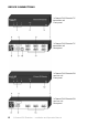
EXPLANATION OF CONNECTIONS
1 LED Lights up when the video signal is active
2 LED Power Lights up when the power supply is active
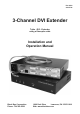
3 3-Channel DVI Extender TX
Label identifying the TX transmitter unit
4 Switch Switches the power supply on and off
5 Air outlet Ventilation duct where the heated outgoing air is vented.
Please do not cover!
6 DVI OUT 1-3 Optional local connections for linking video output devices
to the TX transmitter unit
7 Air intake Ventilation duct for air intake in on both sides.
Please do not cover!
8 Power connector For connecting the supplied power cable
9 Optical MTP®/MPO port for connecting the fi beroptic cable with
MTP®/MPO female / female plugs
10 RS232 RJ45 port for connecting the serial cable for device
confi guration and fi rmware updates
11 DVI IN 1-3 Input port for the video signal
Connection to the video source
Importing EDID (page 25)
Connecting cable included in deliverables
12 3-Channel DVI Extender RX
Label identifying the RX receiver unit
13 DVI OUT 1-3 Output port for the digital video signal
Connection to video output device via connecting cable