
User's Manual

724-746-5500 | blackbox.com
724-746-5500 | blackbox.com
Page 229
LGB5028A User‘s Manual
Appendix C: Cables
Appendix C. Cables
C.1 Twisted-Pair Cable and Pin Assignments
For 10BASE-T/100BASE-TX connections, the twisted-pair cable must have two pairs of wires. For 1000BASE-T connections, the
twisted-pair cable must have four pairs of wires. Each wire pair is identified by two different colors. For example, one wire might
be green and the other, green with white stripes. Also, an RJ-45 connector must be attached to both ends of the cable.
CAUTION: DO NOT plug a phone jack connector into any RJ-45 port. Use only twisted-pair cables with RJ-45 connectors that
conform with FCC standards.
CAUTION: Each wire pair must be attached to the RJ-45 connectors in a specific orientation.
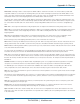
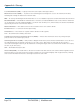
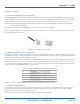
Figure C-1 illustrates how the pins on the RJ-45 connector are numbered. Be sure to hold the connectors in the same orientation
when attaching the wires to the pins.
Figure C-1. RJ-45 connector pin numbers.
C.2 10BASE-T/100BASE-TX Pin Assignments
Use unshielded twisted-pair (UTP) or shielded twisted-pair (STP) cable for RJ-45 connections: 100-ohm Category 3 or better cable
for 10-Mbps connections, or 100-ohm Category 5 or better cable for 100-Mbps connections. Also be sure that the length of any
twisted-pair connection does not exceed 328 feet (100 m).
The RJ-45 ports on the switch base unit support automatic MDI/MDI-X operation, so you can use straight-through cables for all
network connections to PCs or servers, or to other switches or hubs. In straight-through cable, Pins 1, 2, 3, and 6 at one end of
the cable are connected straight through to Pins 1, 2, 3, and 6 at the other end of the cable. When using any RJ-45 port on this
switch, you can use either straight-through or crossover cable.
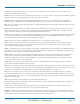
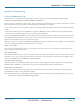
Table C-1. 10BASE-T/100BASE-TX MDI and MDI-X port pinouts.
Pin MDI Signal Name MDI-X Signal Name
1 Transmit Data plus (TD+) Receive Data plus (RD+)
2 Transmit Data minus (TD-) Receive Data minus (RD-)
3 Receive Data plus (RD+) Transmit Data plus (TD+)
4 Receive Data minus (RD-) Transmit Data minus (TD-)
NOTE: The “+” and “-” signs represent the polarity of the wires that make up each wire pair.
C.3 Straight-Through Wiring
If the twisted-pair cable will join two ports, and only one of the ports has an internal crossover (MDI-X), the two pairs of wires
must be straight-through. (When auto-negotiation is enabled for any RJ-45 port on this switch, you can use either straight-
through or crossover cable to connect to any device type.)
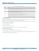
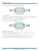
You must connect all four wire pairs as shown in Figure C-2 to support Gigabit Ethernet.