PIN NUMBER: 0558CN1404 Rev 1 Fire Break [With ACS2 Remote System] TECHNICAL MANUAL For use with Natural Gas (G20) or LPG (G31) Important It is recommended, even if you have fitted these appliances before, that you take the time to read through these instructions and follow them step by step. Serial Number ……………………………… Please quote this serial number when making a claim. The Warranty is valid for 1 Year from date of delivery.
This manual must be handed to the owner of the property once the appliance has been installed and commissioned.
Contents Page Page Page Page Page Page Page Page Page Page Page Page Page Page Page Page Page Page Page Page Page Page Page Page Page Page Page 3 4 6 7 8 9 10 11 12 13 14 26 27 29 30 31 31 32 33 34 35 35 37 38 38 39 41 Commissioning Results & Checklist Technical Data Introduction Unpacking the Appliance General Installation Instructions Mains Electrical Power Supply Gas Supply Enclosure Construction & Parts Enclosure Part Identification Burner Construction Installation Instructions Positioning the Magic E
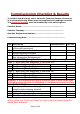
Commissioning Checklist & Results To validate the Warranty and to help with Technical Issues all sections of the Commissioning Sheet must be completed and readings recorded. The complete fireplace must be installed by a Gas safe Engineer.
Page 5 of 56
Dimensions The fire is supplied with a firebox including gather unit. When constructing the builders opening an allowance must be made for both gas and electrical connections and adjustments.
Introduction TO AVOID COSTLY INSTALLATION MISTAKES PLEASE READ THESE INSTRUCTIONS BEFORE STARTING TO INSTALL THE APPLIANCE. THE MOST COMMON FAULTS CAUSED DURING INSTALLATION ARE INCORRECT GAS PRESSURE AND INCORRECT WIRING OF THE MANUAL WALL SWITCH. Important Note: Every FIREBREAK is fully built onsite at the CVO factory prior to being shipped to ensure that all parts fit together correctly. The burner is given a total of 44 performance checks to ensure it operates correctly and inline with CE approval.
Unpacking the Appliance Read these instructions fully before proceeding. • Parts o o o o o o o Supplied: Black Steel Enclosure Black Steel Gather Gas Burner with Remote Control [Pre-Fitted to Enclosure] Installation Kit with Installation Booklet. Remote Hand Set Stone Sections : 13 Pieces in Total Mains Power Adaptor The FIREBREAK involves a large number of heavy stone parts which must be handled with great care. Carefully examine the carton for damage before unpacking.
General Installation Instructions This fire is intended for decorative purposes. The installation must be in accordance with National Regulations and all parts of the installation must be carried out by a qualified GAS SAFE installer. Prior to installation, ensure that the local distribution conditions (identification of the type of gas and pressure and the adjustment of the appliance) are compatible. The builders opening or fireplace opening must be constructed of a noncombustible material.
Mains Electrical Power Supply The fire is supplied with a 240V mains adaptor which must be connected to a 3A fused power outlet. The mains adaptor is connect to the fire via a power socket on the remote housing. WARNING: Care must be taken to ensure the power cable is routed away from any hot surfaces.
Gas Supply • • • • • • • • This is a high power appliance which requires a strong and steady gas supply to avoid the safety device shutting the appliance down. The gas pressure must be maintained at +/- 1mBar of the approved pressure as shown on the data plate at all times – this requires testing the appliance with the other gas appliance in the home both switched on and switched off. Do not start installing the appliance until the pipe work has been checked.
Enclosure Construction & Parts Page 12 of 56
Enclosure Part Identification Page 13 of 56
Bronze Version This is the same size as the Stone Version with only minor differences. If in doubt about assembling the Bronze version please call 01325-327221. Burner Construction Every CVO Fire is tested for 1 hour at the factory. This includes 44 individual function checks. This ensures the appliance is supplied in a fully working condition. Take some time to review the burner construction taking note of the positions of the main components and connections.
Installation Instructions A qualified person should complete all building work; a qualified and competent person to all relevant national legislative controls must carry out the installation of gas burners, mechanical extraction, flue systems and remote control units. Final responsibility for the complete installation is with the Gas Safe Engineer who connects this appliance to the gas supply.
The gather supplied with the fireplace must be used. This can be inserted into the fireplace opening and then lowered onto the enclosure before being sealed in place with silicone fire cement. The enclosure should be fitted within the opening with the front edge “flush” with the final finished wall. The enclosure once in place, should be drilled and secured to the fireplace opening using plugs and screws. This should be done taking great not to damage the burner or remote system.
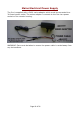
IMAGE #1 The gather must be used in all installations. The gather mounts directly on top of the enclosure. It is possible to insert the gather into the fireplace opening first then slide in the enclosure and lower the gather on to the enclosure. This allows for a smaller construction opening. ITEMS N – M – O These form the back sections. Very carefully lift over the burner and lock into the top slot. Fit item N and O first then fit M last and slide them together to form a complete back.
IMAGE 2 & 3 Once in place the gather must be secured with the screws provided. Then sealed with a high temperature silicone fire cement. At this stage the electrical mains connections, manual wall switch and the gas supply connected ready for testing and commissioning.
IMAGE 4 & 5 ITEMS N – M – O These form the back sections. Very carefully lift over the burner and lock into the top slot. Fit item N and O first then fit M last and slide them together to form a complete back. The stone is fitted loose to allow it to expand. ITEM A – B These are the side pieces. Apply a small amount of Fire Cement to the sides of the black enclosure. Ensure that no cement touches the stone. Carefully slide in the side pieces of stone.
IMAGE 6 & 7 ITEM C Carefully insert the rear shelf ensuring the sloping part is facing forward. Ensure that the pilot assembly on the burner is not disturbed.
IMAGE 8 & 9 ITEMS D & E Carefully insert the small in fill stone sections on both sides.
IMAGE 10 & 11 ITEM F Fitting the Shelf requires two people. Take care not to chip the stone on the sides.
IMAGE 12 The front shelf locates under the two clips inside the enclosure this ensures the shelf is in the correct position for fire operation and the shelf cannot move. IMAGE 13, 14 & 15 – Fitting the Stone Trim The stone facia can now be fitted providing the wall surface is perfectly level both vertically and horizontally. Important: If the wall is not level, it should be skimmed until level. Fractures in the facia / surround can occur if fitted to a wall with an uneven surface. See image below.
WARNING: The stone trim is supplied in 6 pieces. Take time to review the polished sides and unpolished sides. The unpolished side must be bonded to the wall. To bond the stone use high temperature silicone fire cement or a high temperature instant grab adhesive. UPPER TRIM The upper trim must be fitted to allow the stone shelf to be removed when the fire needs to be commissioned and also for servicing. To do this a small gap of 2mm gap is required under the side trims before they are bonded to the wall.
ITEMS L – J – K Use Fire Cement on the sides and along the top to bond the stone to the wall. The stone should be central and spaced equally on both sides. Take note of the comments on the previous page regarding spacing the lower pieces [see image on page 23]. LOWER TRIM. ITEMS G – H - I Using Silicone Fire Cement bond the two smaller sections to the wall ensuring they are inline with the upper trim. Take part G and bond this to the three lower struts ensuring it is in line with the rear trim pieces.
IMAGE 16 This is the final finished assembly with the stone in place. WARNING – FRONT STONE This is a “Floating Hearth” to protect the user from the flame. It must not be leant on or heavy items placed on it. Failure to observe this will result in the stone being damaged.
Positioning the Magic Eye The Magic eye is supplied within the burner housing. Great care should be taken when handling this component. The eye should be positioned on the wall under the lower stone pieces with the curved/domed face forward. There must be direct “line of sight” between the hand set and the magic eye to ensure the hand set works correctly and efficiently.
Commissioning the Fire Use the sheet on Page 3 to record the results of the commissioning procedure. This will allow the CVO technical team to resolve any installation issues that arise. Before starting the fire check it complies with the instructions detailed earlier in this manual. Check the Data Plate to review the required gas type and pressure. Light the appliance to allow air to be purged from the system. This may take a long time depending on the pipe work.
WARNING: At all times the gas pressure must be within +/- 1 mBar of the rated stated on the data plate. For example a G20-20mBar Natural Gas Appliance must be 19mBar to 21mBar. Failure to observe this will render the appliance unreliable and possibly dangerous. 5. Ensure all other gas appliances in the home are switched off. With the appliance switched off test the inlet pressure. Does it comply with the above instructions? Write down the result in the commissioning sheet.
TECHNICAL HELP SECTIONS Fault Diagnosis/Troubleshooting Every CVO fire is tested in the factory and give a 40 point check to ensure it operates correctly. It is highly unlikely it would not operate when installed as designed. The biggest cause of installation problems with this fire are caused by incorrect GAS PRESSURE. This is normally due to ignoring the instructions in the section “READ THIS FIRST” where is clearly states to check the gas pipe work before installing the fire.
Oxygen Depletion Pilot System The pilot light and flame sensing device fitted to this fire is also an atmosphere sensing device. If for any reason any part of the pilot assembly is to be replaced ALL the assembly including the pilot burner, thermocouple, and electrode must be exchanged complete for an original manufacturer's pilot assembly only. This atmosphere sensing device is not adjustable and must not be put out of action.
Burner Flame The flame on this type of appliance is normally directed towards the rear of the enclosure. This is normal due to the opening size and flue system. The flame will never stand “upright”. It is to be expected that over time the surface on the rear of the enclosure will tarnish. This is typical “wear and tear” for a gas fire. If the flame is drawn under the shelf this highlights a serious installation fault and the appliance must not be operated until the cause is found.
Quick Reference Fault Diagnosis Symptom Check List The system “beeps” all the time. There is a fault diagnosis system built into the battery remote. The remote gives out a sequence of “beeps”. This is a code which indicates a fault. See page 38 for details. Appliance clicks but no spark or weak spark. Check spark lead is connected properly. Check spark electrode is in the correct area and the gap correctly distanced to the pilot. Check for a good spark. Check the spark is in the right area.
Remote Control Components Page 34 of 56
Battery Remote System – Alarm Sequence This fire is operated via a battery remote system with AA batteries. The remote system has a built in alarm system which indicates and faults which may arise. This is shown by a sequence of a pre-defined number of “beeps” corresponds to a certain failure. NOTE: There are two types of black box fitted to this type of appliance. See the black box to identify which one is fitted to your fire.
Service and Aftercare Requirements When completing the annual service of the unit, refer to the enclosed technical installation and operational manual & the remote control instruction document. The gas unit should be installed to the manufacturer’s instructions by a Gas Safe registered gas installer, every 12 months the gas fire unit should undergo a regular service, this work should be carried out by a competent person who is Gas Safe registered, familiar with the CVO Fire range of goods.
Servicing Procedure • • • • • • • • • • Turn off the fire and allow cooling time. Turn off the gas supply at the isolation tap. Remove the fascia. Using a Phillips style screwdriver, loosen the screws on the mixer tube then undo the injector nut, and remove the injector. Clean the injector and remove blockages. Do not use a needle or wire, as this may widen the journals, which are set to the C V O test standards. Using a soft brush or vacuum cleaner, carefully remove any debris from the burner unit.
Exchangeable Components List CVO Item Part Description Code Injectors AC002 1.60mm Gas Type Code Number Qty per Fire Engineer Exchange Parts User Exchange Parts LPG 160 2 Yes No AC080 1.
Fitting Spare Parts There are no “user” replacement parts available for this fire. Spare parts are not returnable. CVO Fire cannot accept responsibility for incorrect parts being ordered. When ordering replacement components or requesting technical assistance, you should at all times quote the following: • • • Type of fire & Gas supply (LPG or NG) as shown on Data Plate Unit serial number as shown on Data Plate or front of booklet.
Fault Diagnosis/Troubleshooting Symptom Check List Check Remote Handset is working properly and battery is charged Unit does not respond. Remote handset does not work. Hardwire switch does not work. Unit clicks but no spark or weak spark. Unit sparks but does not light pilot.
Burner lights but turns off after a few minutes Flame is laying back or being sucked under the burner LPG Bottle Users Check that the pilot lights early on ignition clicks Check ventilation is not too strong and the flame is not blowing off the thermocouple Check thermocouple nut is properly secured to the interrupter block on the valve Check ventilation is not too strong and the flame is not blowing off the thermocouple Check gas working pressure is correct, NG20mBar, LPG 37mBar If fire is running on LP
PIN NUMBER: 0558CN1404 Rev 1 Fire Break USER HANDBOOK Spirit Fires Limited. 4 Beaumont Square, Aycliffe Industrial Park, Newton Aycliffe, County Durham, DL5 6XN. This manual must be handed to the owner of the property once the appliance has been installed and commissioned. WARNING: THE FRONT STONE PROJECTION IS NOT A SHELF. IT MUST NOT BE LEANT ON OR HEAVY ITEMS PLACED UPON IT.
THE FLAME. FAILURE TO OBSERVE THIS MAY RESULT IN DAMAGE OR INJURY.
Contents Page Page Page Page Page Page Page Page Page Page Page 43 44 47 48 49 50 50 52 52 53 54 Gas Fire User Instructions Appliance Start Up/Shutdown Lighting The Fire with the Manual Switch Shutdown if the Handset is Faulty Infra Red Remote Replacing the Battery Warning: Front Stone Hearth Cleaning Instructions Service and Aftercare Requirements Warning: Fire Guards & Hearths Warranty Information Contact Details Page 44 of 56
Gas Fire User Instructions General This fire is intended for decorative purposes. Any purpose-provided ventilation should be checked regularly to ensure that it is free from obstruction. The fire should be serviced regularly by a qualified person. The chimney should be swept before the appliance is installed, and should be swept and inspected regularly to ensure that all of the products of combustion are entering the flue and there is no excessive build up of soot.
Appliance Start Up / Shut Down (Lighting the Fire) The appliance is supplied with an internal battery power supply and is operated via handset. There are 6 x ‘AA’ batteries inside the appliance and 1 x 9V battery in the handset. Only use good quality batteries to ensure a long life. If the main burner or pilot light is extinguished during lighting, do not attempt to re-light the pilot within three minutes.
Infra-Red Remote Operation Infrared systems require “Line of sight” between the handset and the sensor at the appliance, it is a standard safety feature to ensure that the appliance cannot be remotely lit from another room.
• To Summarise: o Button #1 & #2 together – This switches the appliance ON. o Button #1 – This switches the appliance OFF and Resets the Appliance. o Button #2 – This sets the unit into standby mode (pilot only) o Button #3 – This sets the flame at maximum rate. o Button #4 – This sets the flame at minimum rate. Each time a button is pressed a “beep” will be heard.
Lighting the fire with the Manual Switch. There is an optional wall switch. This is a manual switch membrane which can be stuck to the wall. Please ensure that the switch and cable do not become detached during assembly. Refer to the remote fault diagnosis if the unit “beeps” repeatedly. If the switch is not to be used the remote “link” must be fitted to the remote black box. The fire will not operate without either the switch or the link.
How to Shutdown if the Handset is Faulty and the Fire is Lit The appliance has a safety shut down switch which is built into the remote system. This is in the form of a button fitted inside the appliance. In the unlikely event that the wall switch is not fitted and the handset is lost, damaged or broken while the fire is lit the fire can be shutdown by pressing this button. Safety Shutdown Procedure • • • Carefully lift the front shelf taking care that the appliance will be hot.
Infra-Red Remote Replacing the Battery Page 51 of 56
WARNING – Front Stone The front piece of stone is designed to be a “Floating Hearth” to protect the user from the flame. It is not a shelf! must not be leant on or heavy items placed on the top of it. Failure to observe this will result in the stone being severely damaged. This is a very costly item to replace and damage is not covered by the warranty. Cleaning Instructions Before cleaning the appliance turn off the Fire unit and allow it to cool for a number of hours.
Removing scuff marks Removal of scuff marks should be carried out in the same manner as if attempting to remove a spillage. However on Limestone it may be necessary to use a scotch brite pad with a slight scrubbing action to remove stubborn marks. If the scuff mark persists it may be necessary to use a stronger cleaner. Please contact CVO Fire for details. Powders, soot, ash or grit These should be removed without the use of liquids of any kind.
Service and Aftercare Requirements When completing the annual service of the unit, refer to the enclosed technical installation and operational manual & the remote control instruction document. The gas unit should be installed to the manufacturer’s instructions by a CORGI registered gas installer, every 12 months the gas fire unit should undergo a regular service, this work should be carried out by a competent person who is CORGI registered, familiar with the CVO Fire range of goods.
WARRANTY INFORMATION Note every CVO fire is assembled at the factory and given 44 functional checks and run for 1 hour prior to being packed and shipped. This ensures that 100% of all fires are in perfect working order. If these instructions are followed there should be no reason why the appliance would not work when installed. This appliance is supplied with a 12 month warranty from the date of delivery. The Warranty covers component failure during the warranty period.
ONLY USE GENUINE REPLACEMENT PARTS. Spirit Fires Ltd, 4 Beaumont Square Aycliffe Industrial Park, Newton Aycliffe County Durham, DL5 6XN T – 01325 327 221 F – 01325 327 292 The information supplied in this manual is correct at the time of publication; Dated on the 8-Feb-2012. There may be changes made in future as we improve our products. If there are any queries please write or call our technical department.