PIN NUMBER: 0558CN1404 Rev 10 Fire River™ TECHNICAL MANUAL & USER HANDBOOK For use with Natural Gas (G20) or LPG (G31) Important It is recommended, even if you have fitted these appliances before, that you take the time to read through these instructions and follow them step by step. Serial Number ……………………………… Please quote this serial number when making a claim. The Warranty is valid for 1 Year from date of delivery.
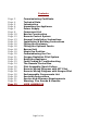
Contents Page Page Page Page Page Page Page Page Page Page Page Page Page Page Page Page Page Page Page Page Page Page Page Page Page Page Page 3 4 5 6 7 8 10 12 13 15 16 18 18 19 20 21 22 23 24 25 27 28 29 30 31 31 33 Commissioning Certificate Technical Data Introduction Unpacking the Appliance Power Supply Component List Burner Construction Remote Control System General Installation Instructions Installation & Building Instructions Fitting the Enclosure Fitting the Optional Fascia Burner Unit Magic Eye
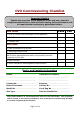
CVO Commissioning Checklist Important Notice Explain the operation of the appliance to the end user, hand the completed instructions to them for safe keeping, as the information will be required when making any guaranteed claims. Pass Fail Flue Check 1. Flue is correct size and length for the appliance 2. Flue Flow test 3. Spillage test Gas Check 1. Gas soundness & let by test 2. Standing pressure test 3.
Page 4 of 44
Introduction This appliance is supplied as a complete suite of enclosure of gas fire burner unit, enclosure and fascia. To comply with the approval this fire must be installed as designed. The fascia must be installed as intended and ventilation to the burner must be provided. Special notice should be taken for the requirements of both the metal and stone fascia versions as the enclosure must be installed differently.
Unpacking the Appliance Read these instructions fully before proceeding. Carefully examine the carton for damage before unpacking. If it is obviously damaged, consult the supplier over whether to proceed. Remove the fire and examine its general condition. Any damage or defects must be reported “before” installing the appliance. No claims will be accepted for damage after the appliance has been installed. If satisfied by the condition proceed with the installation.
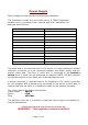
Power Supply Read through this section before starting the installation The installation should only be carried out by a CORGI registered installer and in accordance with national and local regulations for both gas and electricity. Power Supply 230v AC-15%+10%, 50/60 Hz Max power consumption 20VA cos 0.6 (Peak) Stand-by power consumption 1W Ambient Temperature 0.
Component List Specification Page 8 of 44
Page 9 of 44
Burner Construction Take some time to review the burner construction taking note of the positions of the main components and connections. WARNING: Removal of the connections from the remote system or the grommets marked “Electric Supply” or “Hard Wire switch lead” as shown in the burner construction drawings will result in the warranty being invalidated. No claims will be accepted for damage caused by the burner being tampered with.
LPG Version Natural Gas Version Page 11 of 44
Remote Control System The remote system is supplied with both the hard-wired wall mounted switch and infrared hand held system as standard. Both options allow full control of the fire – ON, OFF, UP, DOWN. The wall mounted switch and cable carries low voltage, (20v). The colour code used in the switch wiring diagrams must not be confused with normal mains colour coding. Use and install both systems. This gives increased reliability and is recommended by CVO.
General Installation Instructions This Fire River unit is intended for decorative purposes. The installation must be in accordance with National Regulations and must be carried out by a qualified installer. Clearances between the fire and all combustible materials must conform to National Regulations. This fire must be installed and used in accordance with these instructions.
The pilot light and flame sensing device fitted to this fire is also an atmosphere sensing device. If for any reason any part of the pilot assembly is to be replaced ALL the assembly including the pilot burner, thermocouple, electrode and injector must be exchanged complete for an original manufacturer's pilot assembly only. This atmosphere sensing device is not adjustable and must not be put out of action.
Installation & Building Instructions Building and Installation Work A qualified person should complete all building work; a qualified and competent person to all relevant national legislative controls must carry out the installation of gas burners, mechanical extraction, flue systems and remote control units.
Fitting the Enclosure This fire is supplied with an enclosure and integral burner. IMPORTANT: The appliance is supplied with a fully tested and working gas burner. There is no need to dismantle the burner. This could result in damage to the fire which is not covered by the warranty. No connections should be removed or broken. Removal of any connections will result in the warranty being invalidated. The Fire requires 3 connections: 1. GAS SUPPLY. The fire has an 8mm inlet via an isolation valve.
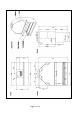
The original fire opening must be closed, using bricks / blocks infill the opening to the required base of the burner, the void behind the brickwork should also be filled; block work or rubble can be used. (It is advisable to install a solid base inside the fire opening to sit the steel framework to). Builders Opening Height – 1000mm Width 965mm Depth – 450mm – The height is to be reduced once the unit has been fitted.
The magic eye should now be installed as shown on page 19 Once all connections are made the burner should be tested for safe operation and gas leaks. For instruction on how to light the fire see the user section on page 25 Once tested the front shelf vanity cover should be fitted taking care not to scratch the enclosure. Fitting the Optional Fascia If using with the optional fascia, fit the fascia to the fire before rendering the wall around to ensure it fits.
Magic Eye Position Page 19 of 44
Commissioning the Fire This appliance requires a specific amount of ventilation to function as designed (correct flame picture), therefore any unused utility access points in the burner tray must be sealed with Aluminium foil tape. When installing the enclosure into an existing chimney with a flue liner the enclosure & gather must be sealed to the existing chimney to ensure that air cannot flow behind the enclosure. Failure to do this will result in serious damage to the burner unit and enclosure.
Brief the customer on the operation of the appliance and give them the instruction booklet for future reference. The customer must be told of the need for regular servicing of the appliance, this will be at least once a year, and be made aware that no rubbish is to be thrown onto the fire bed. The customer must also be aware that purpose provided ventilation should be checked regularly. If you have any questions, or the fire is not operating correctly, Contact the CVO Fire BEFORE you leave the installation.
Reset the Appliance Hand Held Remote Unit To start your appliance, press both buttons on the hand-held remote unit, hold them down for a minimum of three seconds until the ignition process begins which will run for 19-20 seconds before it turns onto the main burner. After the burner has ignited, it can then be switched to high or low using the button on the right side of the handset. Wall Mounted Remote Switch Unlike the hand held unit, you are only required to press one switch.
Fault Finding & Troubleshooting Symptom Check List Check Remote handset is working properly and battery is charged Unit does not respond. Check power supply has not been switched off Check fuses in spur Check wiring is correct on fire and hardwire switch Remote Handset Does not work Hardwire manual switch does not work. Unit clicks but no spark or weak spark.
The Remote Control Black Box Remote Valve NG Version Page 24 of 44 LPG Version
Pilot Assembly / Spark Failure The gap between the pilot electrode and the pilot should be 3.5 – 4.5mm and normally adjustment is not necessary (the electrode is very brittle). The spark should jump across the gap between the electrode and the gas outlet on the pilot head. If the ignitor fails, a lighted taper can be inserted into the pilot area to check that gas is reaching the pilot.
SEAGAS PILOT ASSEMBLY Page 26 of 44
Remote Wiring Diagram – With SIT Pilot Page 27 of 44
Remote Wiring Diagram – with SEAGAS Pilot Page 28 of 44
Exchangeable Components List Part Code Item Description Code Number Engineer Exchange Parts User Exchange Parts AC001 Pilot Assembly SIT 9103 [NG] Yes No AC066 Pilot Assembly P4-70 [NG] Yes No AC006 Pilot Assembly P4-14 [LPG] Yes No AC058 Pilot Assembly SIT 9272 [LPG] Yes No AC004 Injector - NG 090 [ x 2] Yes No AC021 Injector - NG 460 [ x 2] Yes No AC063 Injector - NG 440 [ x 2] Yes No AC069 Injector - NG 340 [ x 2] Yes No AC096 Injector - NG 300 [ x 2] Yes
Servicing Instructions General The following servicing procedure should be carried out regularly and only by a qualified person. Note: foreign bodies which can gather on the surface of the burner unit it is inevitable that servicing can be a dusty operation. Suitable precautions should be taken. Important: The pilot and flame sensing device fitted to this fire is also an atmosphere sensing device.
Service and Aftercare Requirements When completing the annual service of the unit, refer to the enclosed technical installation and operational manual & the remote control instruction document. The gas unit should be installed to the manufacturer’s instructions by a CORGI registered gas installer, every 12 months the gas fire unit should undergo a regular service, this work should be carried out by a competent person who is CORGI registered, familiar with the CVO Fire range of goods.
Page 32 of 44
PIN NUMBER: 0558CN1404 Rev 10 Fire River™ USER HANDBOOK Page 33 of 44
Contents Page Page Page Page Page Page Page Page Page 35 36 37 38 39 40 41 42 44 General Lighting The Fire Hardwired Wall Mounted Switch Infra Red Remote Operation Infra Red Remote Replacing the Battery Servicing Instructions Cleaning Instructions Warning Fire Guards and Hearths Contact Details Page 34 of 44
General This fire is intended for decorative purposes. Any purpose-provided ventilation should be checked regularly to ensure that it is free from obstruction. The fire should be serviced regularly by a qualified person. The chimney should be swept before the appliance is installed, and should be swept and inspected regularly to ensure that all of the products of combustion are entering the flue and there is no excessive build up of soot.
Lighting the fire Infra-Red Remote Operation Infrared systems require “Line of sight” between the handset and the sensor at the appliance, it is a standard safety feature to ensure that the appliance cannot be remotely lit from another room.
Hardwired Wall Mounted Switch Press the ON/OFF bottom (left side) for 2-3 seconds (until the spark ignition sequence begins) and release. The ignition sequence will continue for a further 10-15 seconds before the burner is ignited to the “High position.” To switch off press the ON/OFF button for 2-3 seconds. Press the HIGH/LOW button (right side) for 2-3 seconds the appliance will change to low rate. This operation is repeated to switch between high and low.
Infra-Red Remote Operation Infrared (IR) systems require “Line of sight” between the handset and the appliance. This is a standard feature to ensure the appliance cannot be lit from another room.
Infra-Red Remote Replacing the Battery Page 39 of 44
Servicing Instructions Ther only user changeable parts on this fire are the remote handset. To order a new handset call 01325-327221. This appliance must be serviced every 12 months by a GAS SAFE registered engineer.
Cleaning Instructions Before cleaning the appliance turn off the Fire unit and allow it to cool for a number of hours. Before using any cleaning materials test a small area first to ensure compatibility with the appliance finish. CVO Fire cannot be held responsible for damage caused by cleaning the appliance. Burner Bar / Deposits It is normal for the burner bar to show a redish or white deposit. This is caused by bi-products of the gas being burnt and is unavoidable.
Warning: Fire Guards & Hearths If the appliance develops a fault please refer to the fault diagnosis section earlier in this booklet for possible causes. This appliance is supplied with a 12 month warranty from the date of delivery. The Warranty covers defective parts and does not cover typical wear and tear that occurs with a gas fire appliance.
Page 43 of 44
ONLY USE GENUINE REPLACEMENT PARTS. Spirit Fires Ltd, 4 Beaumont Square Aycliffe Industrial Park, Newton Aycliffe County Durham, DL5 6XN T – 01325 327 221 F – 01325 327 292 The information supplied in this manual is correct at the time of publication; Dated on the 8-2-2012. There may be changes made in future as we improve our products. If there are any queries please write or call our technical department.