PIN NUMBER: 0558CN1404 Rev 3 Fire River™ TECHNICAL MANUAL & USER HANDBOOK [With Battery Operated Remote] For use with Natural Gas (G20) or LPG (G31) Important It is recommended, even if you have fitted these appliances before, that you take the time to read through these instructions and follow them step by step. Serial Number ……………………………… Please quote this serial number when calling to discuss installation and spare part requests. The Warranty is valid for 1 Year from date of delivery.
Contents Page Page Page Page Page Page Page Page Page Page Page Page Page Page Page Page Page Page Page Page Page Page Page Page Page Page Page Page 3 4 5 6 7 8 9 10 12 16 18 19 19 20 22 23 24 25 26 28 29 30 30 32 33 34 37 39 Technical Data READ THIS FIRST Unpacking the Appliance Parts List Construction Drawings Gas Burner Construction Remote Control System General Installation Information Building & Installation Work Installing the Enclosure Fitting the Magic Eye Fitting the Optional Trim Seal the Flue a
Page 3 of 52
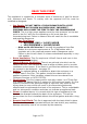
READ THIS FIRST This appliance is supplied as a complete suite of enclosure of gas fire burner unit, enclosure and fascia. To comply with the approval this fire must be installed as designed. • Gas Supply: DO NOT INSTALL THE APPLIANCE UNTIL A PIPE WORK FLOW RATE CHECK HAS BEEN DONE. INCORRECT PRESSURE WILL CAUSE THE FIRE TO FAIL THE COMISSIONING CHECK. This is a high power appliance and the inlet pressure “at the test point in the fire” with the fire operating on full must pass the commissioning test.
Unpacking the Appliance Read these instructions fully before proceeding. Carefully examine the carton for damage before proceeding. If it is obviously damaged, please contact supplier over whether to proceed. Remove the fire and examine its general condition. If satisfied by the condition, proceed with the installation. PLEASE NOTE no claims will be accepted for damaged or faulty components once the appliance has been installed.
Fire River Parts List Parts List • • Fire is supplied as a Kit: o Brushed Steel Enclosure. o Front Shelf. o Burner Unit with Remote Control [pre-fitted] o Instruction Booklet o Remote Control Handset Optional Parts [if ordered] o Gather Unit o Fascia Trim. o Manual Wall Switch [see supplement] o Convert from Battery to Mains Supply [see supplement] Please check your delivery note. Any missing parts must be notified within 48 hours of delivery. No claims can be accepted after this period.
Construction Dimensions Page 7 of 52
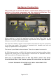
Gas Burner Construction Take some time to review the burner construction taking note of the positions of the main components and the required connections. The burner is pre-fitted to the enclosure – do not remove it. Before starting to install the appliance review the Data Plate fitted to the appliance for the gas type and pressure requirements of the appliance. Ensure these are correct for the property supply.
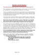
Remote Control System Take some time to learn about the remote system fitted to this fire. This is operated by a fully sequential battery remote system. This is powered by 6 x AA batteries in the fireplace and a 9V battery in the handset. The fire is operated by the Infra Red and the handset must be pointed directly at the magic eye on the fire to work. It requires “line of sight”. Read the section on lighting the fire for more information.
General Installation Information This fire is intended for decorative purposes. The installation must be in accordance with National Regulations and must be carried out by a qualified installer. Clearances between the fire and all combustible materials must conform to National Regulations. This fire must be installed and used in accordance with these instructions.
This fire needs an air vent within the room which will provide a minimum of 100cm2 free air in accordance with National Regulations. In some countries additional ventilation may be required It is recommended that a guard be used for the protection of young children, the elderly or infirm. This fire should be checked regularly to ensure that it is free from obstruction. A qualified person should service the fire regularly.
Building and Installation Work All building and gas installation should be carried out by a qualified and competent person, and must adhere to national and local legislations and regulations. Before Starting READ PAGE 4 FIRST Building work should only commence after a thorough survey of the intended location of the impending installation has been completed and it has been established that the unit can be installed and operated without risk to the owner or tenants of the property or their neighbours.
Gas Supply Consult the Data Plate within the appliance to ensure the correct gas type and pressure is available within the property. Before commencing to create the fire opening for the inglenook unit note that a gas supply is required. The gas supply pipe should run into the installed enclosure from either the rear, left or right hand sides, the gas supply is best run through the left side of the enclosure.
Room Ventilation This fire needs an air vent supplying a minimum of 100cm2 free air into the room from outside. The air vent must comply with current building regulations. Burner Ventilation “TRIMLESS” VERSION When installing the “trimless” version of the Fire River additional burner ventilation must be planned to provide fresh air into the burner box. This work should be planned before starting to install the fire.
Front & Side View Page 15 of 52
Installing the Enclosure This fire is supplied with an enclosure and integral burner. The appliance is supplied with a fully tested and working gas burner. There is no need to dismantle or adjust the burner. Removal of any connections will result in the warranty being invalidated. Great care must be taken when handling the burner to avoid damaging the remote system. If using with the optional Gather, dry fit the gather to the enclosure taking note of where the gather and enclosure overlap.
Gather Unit If the standard gather is not used, the flue must be connected to the enclosure in accordance with GAS SAFE and local regulation. The gather has been designed to allow it to be inserted into the chimney opening and held up while the fire enclosure is installed. The gather must then be attached to the enclosure using the screws provided and sealed with fire cement. When using a flue liner the gather must be sealed to the liner by fire cement. Gas and Battery Connection.
Fitting the Magic Eye (Metal Version) The magic eye must be the correct way round (as shown above) to ensure “line of sight” and correct operation. The burner should be tested for safe operation and gas leaks. For instruction on how to light the fire see the user section on page 40 Once tested the front shelf vanity cover should be fitted taking care not to scratch the enclosure.
Fitting the Metal Fascia The trim is optional and can be fitted after the fire is completed by using the two lower and two upper screws which secure it to the enclosure. The trim should be floating on the wall, not recessed into it. Seal the Flue and Check Burner Ventilation See Page 14 “burner ventilation” before proceeding.
COMMISSIONING THE APPLIANCE WARNING: The burner inlet flow rates are factory set and sealed. Under no circumstances should these settings be changed. The aeration is fixed. Do not change the burner aeration. This fire must not be operated without the heat shield in place over the Black Box. Failure to do this will result in serious damage to the remote system which will not be covered by the warranty. The burner is also tested to 150mBar to ensure there are no gas leaks in the burner.
• • • Now light all other gas appliances in the home and run tests 1-3 again. Record your results in the check sheet. THE PRESSURE AT ALL TIMES MUST BE WITHIN 1MBAR OF THE DATAPLATE READING • IF THE TEST FAILED: If it is not possible to maintain the pressure at the required level, TRANSCO, BORD GAIS or the propane supplier must be called to adjust the governor to the house before the appliance can be commissioned further.
• • The customer must be told not to block the room air vent. The warranty card is to be completed by the registered engineer who has commissioned the appliance. This is to validate the warranty. The card must then be given to the customer for return to the factory.
CVO Commissioning Checklist Important Notice Explain the operation of the appliance to the end user, hand the completed instructions to them for safe keeping, as the information will be required when making any guaranteed claims. Pass Fail Flue Check 1. Flue is correct for appliance 2. Flue Flow test 3. Spillage test Gas Check 1. Gas soundness & let by test 2. Standing pressure test 3. Appliance working pressure (on High Setting) NB All other gas appliances must be operating on full 4. Gas rate 5.
Oxygen Depletion Pilot System There is a highly sensitive oxygen depletion sensor designed into the pilot light. If any part is damaged the entire unit must be replaced. Do not attempt to bend or alter the flame head, thermocouple or aeration hole. Use only genuine spare parts as similar looking parts from other appliances may well give different or inferior performance and could lead to a hazard. Spark / Ignition Failure The gap between the pilot electrode and the pilot should be 3.5 – 4.
Burner Flame The flame on this type of appliance is normally directed towards the rear of the enclosure. This is normal due to the opening size and flue system. The flame will never stand “upright”. It is to be expected that over time the surface on the rear of the enclosure will tarnish. This is typical “wear and tear” for a gas fire. If the flame is drawn under the shelf this highlights a serious installation fault and the appliance must not be operated until the cause is found.
Fault Diagnosis/Troubleshooting Every CVO fire is tested in the factory and give a 40 point check to ensure it operates correctly. It is highly unlikely it would not operate when installed as designed. The biggest cause of installation problems with this fire are caused by incorrect GAS PRESSURE. This is normally due to ignoring the instructions in the section “READ THIS FIRST” where is clearly states to check the gas pipe work before installing the fire.
Symptom The system “beeps” all the time. Appliance clicks but no spark or weak spark. Check List There is a fault diagnosis system built into the battery remote. The remote gives out a sequence of “beeps”. This is a code which indicates a fault. See page 29 for alarm sequence. Check spark lead is connected properly. Check spark electrode is in the correct area and the gap correctly distanced to the pilot. Check for a good spark. Check the spark is in the right area.
Remote Control Components Page 28 of 52
Battery Remote System – Alarm Sequence This fire is operated via a battery remote system with AA batteries. The remote system has a built in alarm system which indicates and faults which may arise. This is shown by a sequence of a pre-defined number of “beeps” corresponds to a certain failure. BLACK BOX – IR Alarm sound description 3 x beeps – Manual Wall Switch Keyboard Failure Substitute the keyboard with another one and verify the sound alarm stops.
Service and Aftercare Requirements When completing the annual service of the unit, refer to the enclosed technical installation and operational manual & the remote control instruction document. The gas unit should be installed to the manufacturer’s instructions by a Gas Safe registered gas installer, every 12 months the gas fire unit should undergo a regular service, this work should be carried out by a competent person who is Gas Safe registered, familiar with the CVO Fire range of goods.
Servicing Procedure • • • • • • • • • • Turn off the fire and allow cooling time. Turn off the gas supply at the isolation tap. Remove the fascia. Using a Phillips style screwdriver, loosen the screws on the mixer tube then undo the injector nut, and remove the injector. Clean the injector and remove blockages. Do not use a needle or wire, as this may widen the journals, which are set to the C V O test standards. Using a soft brush or vacuum cleaner, carefully remove any debris from the burner unit.
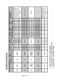
Exchangeable Components List CVO Item Part Description Code Injectors AC002 1.60mm Gas Type Code Number Qty per Fire Engineer Exchange Parts User Exchange Parts LPG 160 2 Yes No AC080 1.
Fitting Spare Parts The only “user” replacement part for this gas fire is the remote handset. All other parts must be fitted by a trained gas engineer. The fitting of replacement parts must be carried out by a qualified GAS SAFE Engineer inline with current regulations. When removing any parts from the remote system these should be replaced in the same manner using the “schematic diagram” in this booklet.
Fitting the Optional Wall Switch Important This work must be carried out by a GAS SAFE REGISTERED ENGINEER.
Remote Diagram Take some time to review the attached diagram NOTE THE POSITION OF THE “LINK” Page 35 of 52
INSTRUCTIONS • • • • • • • • • • Use the gas isolation valve to isolate the gas. Taking care not to damage any components on the circuit board remove the heat shield. Note the position of the link in the circuit diagram. Gently remove the link and replace this with the wall switch cable. Route the cable as require ensuring that it is kept away from hot surfaces. Secure the wall switch in the required place and connect the cable. Refit the heat shield on the remote system. Reconnect gas and check for leaks.
Converting the Fire To Mains Supply This must be done by a GAS SAFE Engineer and trained electrician. 1. Parts Required: a. Mains Power Adaptor b. Mains Power Connector c. These are available as optional spare parts from the customer service department. Call 01325-327221 2. Procedure a. Remove the remote heat shield and disconnect the battery pack, supply lead and reset switch from the fire. b. Replace the reset switch with the power supply cable. c. Connect the power adaptor to the supply cable. d.
Page 38 of 52
PIN NUMBER: 0558CN1404 Rev 3 Fire River™ USER HANDBOOK [With Battery Operated Remote] Page 39 of 52
Contents Page Page Page Page Page Page Page Page Page Page 41 42 45 46 46 47 48 49 50 52 General Information Lighting the Fire - Start/Shutdown Instructions Using the Manual Switch [if fitted] How to Shutdown if the Handset is Lost/Broken. How to Reset the Fire Replacing the Batteries Cleaning Instructions Fire Guards and Hearths Warranty Information.
General Information A qualified GAS SAFE registered installer is required to fully install the appliance, failure to do this may render the appliance dangerous and will invalidate the warranty. This fire is intended for decorative purposes. Any purpose-provided ventilation should be checked regularly to ensure that it is free from obstruction. The fire should be serviced regularly by a qualified person.
Appliance Start Up / Shut Down Instructions (Lighting the Fire) The appliance is supplied with an internal battery power supply and is operated via handset. There are 6 x ‘AA’ batteries inside the appliance and 1 x 9V battery in the handset. Only use good quality batteries to ensure a long life. If the main burner or pilot light is extinguished during lighting, do not attempt to re-light the pilot within three minutes.
• o o o o o To Summarise: Button #1 & #2 together – This switches the appliance ON. Button #1 – This switches the appliance OFF and Resets the Appliance. Button #2 – This sets the unit into standby mode (pilot only) Button #3 – This sets the flame at maximum rate. Button #4 – This sets the flame at minimum rate. Each time a button is pressed a “beep” will be heard.
Infra-Red Remote Operation Infrared systems require “Line of sight” between the handset and the sensor at the appliance, it is a standard safety feature to ensure that the appliance cannot be remotely lit from another room.
Lighting the fire with the Manual Switch. There is an optional wall switch. This is a manual switch membrane which can be stuck to the wall. Please ensure that the switch and cable do not become detached during assembly. Refer to the remote fault diagnosis if the unit “beeps” repeatedly. If the switch is not to be used the remote “link” must be fitted to the remote black box. The fire will not operate without either the switch or the link.
How to Shutdown the fire if the Handset is Faulty or Lost while the Fire is Lit The appliance has a safety shut down switch which is built into the remote system. This is in the form of a button fitted inside the appliance. In the unlikely event that the wall switch is not fitted and the handset is lost, damaged or broken while the fire is lit the fire can be shutdown by pressing this button. Safety Shutdown Procedure • • Carefully lift the front shelf taking care that the appliance will be hot.
Replacing the Batteries Main Appliance Batteries To ensure a long life use a set of brand new lithium batteries. Always replace all 6 batteries at the same time otherwise the alarm will continue to sound. The remote has a memory and will highlight old batteries being used. If the remote alarm indicates that the batteries are “flat” do not use the appliance. Ensure the appliance is switched off and has had time to “cool down” before starting to replace the batteries.
Hand Set Batteries Turn over the hand set and unclip the battery cover. Fit a new 9V battery and refit the battery cover. The appliance should now operate normally. NOTE: CVO Fire recommends that only high quality batteries are used in this appliance. Lithium batteries provide the longest life. Cleaning Instructions Before cleaning the appliance turn off the Fire unit and allow it to cool for a number of hours.
Wax Never place candles on the burner shelves. If molten wax enters the burner unit – DO NOT USE THE APPLIANCE - contact your installer to remove the spillage and ensure the remote system functions correctly. Warning: Fire Guards & Hearths This appliance is not fitted with an integral guard.
WARRANTY INFORMATION This appliance carries full CE approval and has a long and reliable history. The CE approval ensures that, if installed correctly, the appliance will function as designed. If the appliance develops a fault please refer to the fault diagnosis section earlier in this booklet for possible causes. This appliance is supplied with a 12 month warranty from the date of delivery.
Page 51 of 52
ONLY USE GENUINE REPLACEMENT PARTS. Spirit Fires Ltd, 4 Beaumont Square Aycliffe Industrial Park, Newton Aycliffe County Durham, DL5 6XN T – 01325 327 221 F – 01325 327 292 www.cvo.co.uk The information supplied in this manual is correct at the time of publication; Dated on the 31/1/2012. There may be changes made in future as we improve our products. If there are any queries about this appliance please email info@cvoco.uk or call our technical department on 01325-327221.