
Network Hardware User Manual


12
CAT5 AUDIO/VIDEO SPLITTERS
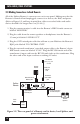
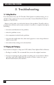
3.3 Making Connections to Each Remote
All of the Splitter Remote’s connectors are on its rear panel. Making sure that the
Remote is turned off and unplugged, connect it to devices, the Hub, and power.
(Refer to Figure 3-2, and keep in mind that cables to attached video and audio
devices shouldn't be longer than 5 m [16.4 ft.].)
1. Plug the remote monitor’s cable into the Remote’s HD15 female connector
labeled “MONITOR.”
2. Plug the cable from the remote speakers or headphones into the Remote’s
3.5-mm jack labeled “AUDIO OUT.”
3. Plug the CAT5 twisted-pair cable that will run to your Hub into the Remote’s
RJ-45 jacks labeled “TO CENTRAL UNIT.”
4. Plug the external transformer’s attached output cable to the Remote’s 4-pin
DIN female connector labeled “9 VAC.” Plug the IEC 320 female end of the
transformer’s input cord into the IEC 320 male inlet on the transformer. Plug
the other end of the input cord into a working AC outlet.
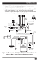
Figure 3-2. The rear panel of a Remote and its device, local Splitter, and
power attachments.
RJ-45 M to
Central Unit
port
RJ-45 M to
port 1, 2, 3, or 4
on Hub
Remote
monitor
4-pin DIN M
to Power port
Power
supply
To AC
outlet
HD15 M to Local
Monitor port
Splitter
Remote
CAT5 STP
cable to
Hub
Remote
speakers
3.5-mm stereo plug
to Audio Out port