ACS2009A-R2-xx, ACS2028A-R2-xx ACS2209A-R2-xx, ACS2228A-R2-xx ACS4001A-R2-xx, ACS4022A-R2-xx ACS4201A-R2-xx, ACS4222A-R2-xx DVI-D-Fiber-KVM-Extender Single and DualHead Manual http://www.blackbox.
DVI-D FIBER KVM-EXTENDER Welcome to the DVI-D Fiber KVM-Extender Family! Thank you for purchasing an DVI-D Fiber KVM-Extender! We appreciate your business, and we think you’ll appreciate the many ways that your enhanced RGB Graphic system will save you money, time, and effort. That’s because our DVI-D Fiber KVM-Extender is all about breaking away from the traditional model of attaching a new display to DVI graphic source.
DVI-D FIBER KVM-EXTENDER Copyrights and Trademarks ©2008. All rights reserved. This information may not be reproduced in any manner without the prior written consent of the manufacturer. Information in this document is subject to change without notice and the manufacturer shall not be liable for any direct, indirect, special, incidental or consequential damages in connection with the use of this material.
DVI-D FIBER KVM-EXTENDER 4
DECLARATION OF CONFORMITY EUROPEAN UNION DECLARATION OF CONFORMITY This is to certify that, when installed and used according to the instructions in this manual, together with the specified cables and the maximum cable length <3m, the Units: ACS2009A-R2-MM, ACS2009A-R2-SM, ACS2209A-R2-MM, ACS2209A-R2-SM ACS4001A-R2-MM, ACS4001A-R2-SM, ACS4201A-R2-MM, ACS4201A-R2-SM ACS2028A-R2-MM, ACS2028A-R2-SM, ACS2228A-R2-MM, ACS2228A-R2-SM ACS4022A-R2-MM, ACS4022A-R2-SM, ACS4222A-R2-MM, ACS4222A-R2-SM are shielded agai
DVI-D FIBER KVM-EXTENDER Safety Precautions and Installation Guidelines To ensure reliable and safe long-term operation, please note the following installation guidelines: • Only use in dry, indoor environments. • If the building has 3-phase AC power, try to ensure that equipment connected to the Local and Remote units is on the same phase. • The Remote unit, Local unit and any power supplies can get warm. Do not locate them in an enclosed space without any airflow.
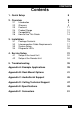
CONTENTS Contents 1. Quick Setup 8 2. Overview 9 2.1 2.2 2.3 2.4 2.5 2.6 Introduction Glossary Features Product Range Compatibility How to Use This Guide 3. Installation 3.1 3.2 3.3 3.4 Package Contents Interconnection Cable Requirements System Setup Diagnostic LEDs 4. Service Setup 4.1 4.2 Setup at the Local Unit Setup at the Remote Unit 9 9 11 12 13 14 15 15 17 18 29 31 32 34 5.
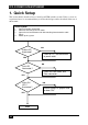
DVI-D FIBER KVM-EXTENDER 1. Quick Setup This section briefly describes how to install your KVM extender system. Unless you are an experienced user, we recommend that you follow the full procedures described in the rest of this manual. Install system 1. 2. 3. 4. Connect Remote unit to KVM. Connect Local unit to CPU or switch. Connect Local and Remote units with matching interconnection cable (Fiber). Power up the system. NO Power LED illuminated? YES Check p.s.u.
OVERVIEW 2. Overview 2.1 Introduction A Fiber KVM Extender is mainly used, to extend the maximum distance between a CPU and his Keyboard / Monitor / Mouse considerably. In addition they are beneficial in installations in electromagnetic hazardous environments (EMI). Normal Keyboard-/ Monitor-/ Mouse extender cables (and Extender using traditional cables) cannot go so far and EMI interferences may reduce the maximum distance and/or reliability.
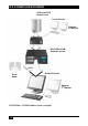
DVI-D FIBER KVM-EXTENDER CPU with DVI-D Graphic card Local Console Optional 2nd Monitor DVI-D Fiber KVMExtender system Serial / Audio Remote Console Optional 2nd Monitor DVI-D Fiber – KVM Extender system (example) 10
OVERVIEW 2.3 Features All members of the DVI-D Fiber - DVI KVM Extender Series offer the following features: • Support for DVI-D Graphic cards (all devices) • Support for PS2-Keyboard and PS2-Mouse (ACS2028A-R2-xx and ACS2228A-xx) • Support for USB-Keyboard and USB-Mouse (ACS4022A-R2-xx and ACS4222A-xx) Devices with USB- connectors support ONLY Keyboard and Mouse.
DVI-D FIBER KVM-EXTENDER 2.
OVERVIEW 2.5 Compatibility Interface Compatibility • Digital Video (DVI-D): Digital Video standard, installed by Digital Display Working Group (www.ddwg.org) R, G, B, CLOCK in a data stream with up to 3x 1,6 GBit/sec. Signals are TMDS Level. • PS/2 Keyboard: Compatible with all standard keyboards. Certain keyboards with enhanced features may also be supported with custom firmware. • PS/2 Mouse: Compatible with all standard 2-button, 3-button and wheel mice.
DVI-D FIBER KVM-EXTENDER 2.6 How to Use This Guide This guide describes the installation and configuration of the DVI-D Fiber – Extender Series. Although the connection and operation of the system is relatively straightforward, you should consider the following before getting started: Connection & Compatibility If you have purchased an Extender Kit, this will contain all the cables required to connect the Local unit to your PC or KVM switch.
INSTALLATION 3. Installation For first-time users, we recommend that you carry out a test placement, confined to a single room, before commencing full installation. This will allow you to identify and solve any cabling problems, and experiment with the KVM extender system more conveniently. 3.
DVI-D FIBER KVM-EXTENDER ACS4001A-R2-xx, ACS4022A-R2-xx, ACS4201A-R2-xx and ACS4222A-R2-xx (additionally): • DVI-D (1,8m) video cable (DVI-D dual link male-to-male) • USB (1,8m) cable (USB type A to type B) ACS2209A-R2-xx, ACS2228A-R2-xx, ACS4201A-R2-xx and ACS4222A-R2-xx (additionally): • DVI-D (1,8m) video cable (DVI-D dual link male-to-male) ACS2028A-R2-xx, ACS4022A-R2-xx (additionally): • Serial link cable (1.
INSTALLATION 3.2 Interconnection Cable Requirements To connect the Local and Remote units you will need: • DVI, PS2-Keyboard, PS2-Mouse: Connect the supplied KVM CPU cable set to your CPU (KVM.- Switch, etc.). Please ensure that the connection is tension-free! Devices ACS2028A + ACS2228A • DVI, USB-Keyboard, USB-Mouse: Connect the supplied KVM CPU cable set to your CPU (KVM.- Switch, etc.).
DVI-D FIBER KVM-EXTENDER 3.3 System Setup To install your DVI-D Fiber – Extender system: 1. Switch off all devices. 2. Connect your keyboard, monitor(s) and mouse to the Remote unit (depending on device type). Please ensure, to not swap Mouse- and Keyboard connector. The Keyboard connector is purple and the Mouse connector is green. 3. Using the supplied CPU KVM cable(s), connect the keyboard, monitor(s) and mouse connectors on the computer (or KVM switch).
INSTALLATION Connect to CPU: DVI, keyboard, mouse local DVI-Monitor port Connect to Local console monitor Local keyboard/ mouse port Solely Keyboard may be plugged in directly, keyboard/mouse through equipped adapter DVI-D Fiber KVM-Extender Type ACS2009A-R2-xx Local Unit remote DVI-Monitor port– connect to Remote console monitor Remote mouse port Remote keyboard port DVI-D Fiber KVM-Extender Type ACS2009A-R2-xx Remote Unit Connect to 5V Power supply INTERCONNECT – carries video and data signals – c
DVI-D FIBER KVM-EXTENDER Connect to CPU: 2 DVI-Graphic card nd Connect to CPU: st 1 DVI-Graphic card, keyboard, mouse nd 2 local DVI-Monitor port Connect to Local nd console 2 monitor local DVI-Monitor port Connect to Local console monitor Local keyboard/ mouse port Solely Keyboard may be plugged in directly, keyboard/mouse through equipped adapter DVI-D Fiber KVM-Extender Type ACS2209A-R2-xx Local Unit nd 2 remote DVI-Monitor port Connect to Remote nd console 2 monitor st 1 remote DVIMonitor port–
INSTALLATION Connect to CPU: DVI, keyboard, mouse Connect to CPU: Audio OUT Audio IN local DVI-Monitor port Connect to Local console monitor Connect to CPU: serial interface Local keyboard/ mouse port Solely Keyboard may be plugged in directly, keyboard/mouse through equipped adapter DVI-D Fiber KVM-Extender Type ACS2028A-R2-xx Local Unit Connect to Speakers Microphone remote DVI-Monitor port– connect to Remote console monitor Remote mouse port Connect to: serial device Remote keyboard port DVI-D
DVI-D FIBER KVM-EXTENDER Connect to CPU: 2 DVI-Graphic card nd Connect to CPU: st 1 DVI-Graphic card, keyboard, mouse nd 2 local DVI-Monitor port Connect to Local nd console 2 monitor local DVI-Monitor port Connect to Local console monitor Connect to CPU: serial/ audio ports Local keyboard/ mouse port Solely Keyboard may be plugged in directly, keyboard/mouse through equipped adapter DVI-D Fiber KVM-Extender Type ACS2228A-R2-xx Local Unit nd 2 remote DVI-Monitor port Connect to Remote nd console 2 m
INSTALLATION Connect to 5V Power supply INTERCONNECT – carries video and data signals – connect to Local/ remote unit with Fiber cable Fiber-Plug type: LC DVI-D Fiber KVM-Extender Type ACS2028A-R2-xx Local/ Remote Unit nd INTERCONNECT – carries 2 video – connect to Local/Remote unit with Fiber cable Fiber-Plug type: LC st Connect to 5V Power supply INTERCONNECT – carries 1 video and data signals – connect to Local/ Remote unit with Fiber cable Fiber-Plug type: LC DVI-D Fiber KVM-Extender Type ACS222
DVI-D FIBER KVM-EXTENDER Connect to CPU: DVI graphic card local DVI-Monitor port Connect to Local console monitor Connect to CPU: USB DVI-D Fiber KVM-Extender Type ACS4001A-R2-xx Local Unit remote DVI-Monitor port– connect to Remote console monitor Remote keyboard/mouse port DVI-D Fiber KVM-Extender Type ACS4001A-R2-xx Remote Unit Connect to 5V Power supply INTERCONNECT – carries video and data signals – connect to Local/ remote unit with Fiber cable DVI-D Fiber KVM-Extender Type ACS4001A-R2-xx Loca
INSTALLATION Connect to CPU: 2 DVI-Graphic card nd Connect to CPU: st 1 DVI-Graphic card nd 2 local DVI-Monitor port Connect to Local nd console 2 monitor st local 1 DVI-Monitor port Connect to Local st console 1 monitor Connect to CPU: USB DVI-D Fiber KVM-Extender Type ACS4201A-R2-xx Local Unit nd 2 remote DVI-Monitor port Connect to Remote nd console 2 monitor st 1 remote DVIMonitor port– connect st to Remote console 1 monitor Remote keyboard/ mouse port DVI-D Fiber KVM-Extender Type ACS4201A
DVI-D FIBER KVM-EXTENDER Connect to CPU: DVI graphic card Connect to CPU: Audio OUT Audio IN local DVI-Monitor port Connect to Local console monitor Connect to CPU: serial interface Connect to CPU: USB DVI-D Fiber KVM-Extender Type ACS4022A-R2-xx Local Unit remote DVI-Monitor port– connect to Remote console monitor Connect to Speakers Microphone Connect to: serial device Remote keyboard/mouse port DVI-D Fiber KVM-Extender Type ACS4022A-R2-xx Remote Unit 26
INSTALLATION Connect to CPU: 2 DVI-Graphic card nd Connect to CPU: st 1 DVI-Graphic card nd 2 local DVI-Monitor port Connect to Local nd console 2 monitor st local 1 DVI-Monitor port Connect to Local st console 1 monitor Connect to CPU: serial/ audio ports Connect to CPU: USB DVI-D Fiber KVM-Extender Type ACS4222A-R2-xx Local Unit nd 2 remote DVI-Monitor port Connect to Remote nd console 2 monitor Connect to Speakers Microphone Connect to: serial device st 1 remote DVIMonitor port– connect st
DVI-D FIBER KVM-EXTENDER Connect to 5V Power supply INTERCONNECT – carries video and data signals – connect to Local/ remote unit with Fiber cable Fiber-Plug type: LC DVI-D Fiber KVM-Extender Type ACS4022A-R2-xx Local/ Remote Unit nd INTERCONNECT – carries 2 video – connect to Local/Remote unit with Fiber cable Fiber-Plug type: LC st Connect to 5V Power supply INTERCONNECT – carries 1 video and data signals – connect to Local/ Remote unit with Fiber cable Fiber-Plug type: LC DVI-D Fiber KVM-Extender
INSTALLATION 3.4 Diagnostic LEDs Each DVI-D Fiber KVM-Extender is fitted with four indicator LEDs: Power, Video OK, Data Error, Link Status: The Power LEDs are next to the Power socket.
DVI-D FIBER KVM-EXTENDER LED Appearance Diagnostics Power LED (Red LED) Off On Device not ready Device ready Video Okay (Green LED) Off On No or invalid video signal detected Device ready Link Status (Green LED) blinking On No FIBER connection Device ready Data Error (Green LED) Off blinking / On Device ready Errors through data transmission over FIBER Cable (Cable too long, too high attenuation or too much EMI interferences ) 30
SERVICE SETUP 4. Service Setup For most applications, you shouldn't need not to make any adjustments to set up your DVI-D Fiber KVM-KVM-Extender. Under some special circumstances it could be necessary to setup configuration specials. For some applications, you may need to open the Local Unit and/or the Remote Unit. Unscrew the Philips-type screws at both sides at the bottom of the device. Carefully displace the lower and upper shells of the case.
DVI-D FIBER KVM-EXTENDER 4.1 Setup at the Local Unit After unscrewing and opening the upper shell, please place the device in this orientation: with the Fiber connectors to the right and the electrical connectors to the left. The main PCB then will look like this: JP1, JP2, JP3 Use the diagram to locate jumpers. DDC You can select, whether the DDC is taken from internal DDC table or from local monitor or the DDC information could be downloaded from remote monitor and stored into internal table.
SERVICE SETUP Loading the DDC Information from the Remote Monitor into the internal DDC Table To load the DDC Information from the Remote Monitor into the internal DDC Table, please proceed the following steps: • Power up the CPU, the Local Unit, the Remote (cables to the CPU connected) and the Monitor • Pull the Monitor Cable(s) from the Remote Unit (Dualhead devices: BOTH Monitors!) • Switch ON the Monitor(s) (if switched OFF, Dualhead devices: BOTH Monitors!) • Plug the Video-Cable of the Remote M
DVI-D FIBER KVM-EXTENDER 4.2 Setup at the Remote Unit After unscrewing and opening the upper shell, please place the device in this orientation: with the Fiber connectors to the right and the electrical connectors to the left. The main PCB then will look like this: JP1, JP2, JP3 Use the diagram to locate jumpers. Selecting the moment of switching to the next frame The transmission of screen data in not synchronous to the screen change of the graphic card.
TROUBLESHOOTING 5. Troubleshooting Monitor There isn’t a picture. Check the power supply connection at the local and remote unit. Is the Power (Red LED) at the Local unit illuminated (see page 29)? If not, the internal power-supply may be damaged or there may be an internal error. Check that the Interconnection cable is connected at the Local Unit and the Remote Unit.
DVI-D FIBER KVM-EXTENDER Try a different model of keyboard. If the new keyboard works then original one may be incompatible Check that the Interconnection cable is connected at the Local Unit and the Remote Unit. Is the Link Status LED illuminated (see page 29)? The other console is active. Claim control by any keyboard action or by pressing left and right mouse buttons simultaneously.
TROUBLESHOOTING or horizontally graduated colors – better use monochrome backgrounds. They allow higher compression -> higher frame rates. Your mouse is moving like ‘hanging on a rubber band’ This problem derives from different single problems, which accumulate to a delay between the true mouse movement and displaying the movement of the mouse pointer on the screen. Depending to our measurements, a delay of approx. 100150msec are recognized as disturbing. The total delay comes from (time values are approx.
DVI-D FIBER KVM-EXTENDER Other USB-devices Your USB- device does not work You have connected a non-HID device. There are supported HID devices only.
APPENDIX A: EXAMPLE APPLICATIONS Appendix A: Example Applications This section illustrates some specific applications using the DVI-D Fiber - Extenders: • DVI-D Fiber KVM-Extender with optional, secondary screen.
DVI-D FIBER KVM-EXTENDER • 4 CPU’s – local outputs managed through a KVM- Switch and a single console. Remote Consoles up to 140m away.
APPENDIX B: RACK MOUNT OPTIONS Appendix B: Rack Mount Options DVI-D Cat X KVM- Extender units can be mounted in a 19” rack using the mounting kit: DVI-D Cat X- Rackmount Kit. Two different versions are available – one each for Singlehead and for Dualhead devices. Mounting Instruction Rackmount-Kit ACS1009A-RMK Using the Rackmount-Kit ACS1009A-RMK, up to 4 devices of the device size 103x143x29mm (Singlehead Devices) can be mounted into a 19“-Server Rack. The Rackmount Kit requires 1U Rackspace.
DVI-D FIBER KVM-EXTENDER The Rackmount-Kit ACS1009A-RMK allows, to mount a different count of devices (1…4 pieces): In the leftmost position, you can install a rack mountable p.s.u. type ACS2228A-PS instead of an extender device. This p.s.u. allows, to power up to 3 devices (singlehead or dualhead) Please note:’ - Use the back moved mounting holes to fix the p.s.u. - After mounting the p.s.u., the circuit break switch is not longer easily accessible – it is covered by the cover strip.
APPENDIX B: RACK MOUNT OPTIONS Mounting Instruction Rackmount-Kit ACS2228A-RMK Using the Rackmount-Kit ACS2228A-RMK, up to 4 devices of the device size 103x143x42mm (Dualhead Devices) can be mounted into a 19“-Server Rack. The Rackmount Kit requires 1U Rackspace. Blindplates (in the list of parts delivered) allow to cover unused device positions.
DVI-D FIBER KVM-EXTENDER The Rackmount-Kit ACS2228A-RMK allows, to mount a different count of devices (1…4 pieces): In the leftmost position, you can install a rack mountable p.s.u. type ACS2228A-PS instead of an extender device. This p.s.u.
APPENDIX C: AUDIO/SERIAL SUPPORT Appendix C: Audio/Serial Support Single head KVM devices: The Audio/Serial allows bi-directional stereo audio and a full-duplex serial data link to be sent across the regular interconnection cable in addition to keyboard, mouse and DVI video.
DVI-D FIBER KVM-EXTENDER Audio Interface - Set Up and Operation The audio interface is line-level and is designed to take the output from a sound card (or other line-level) source and be connected to a set of powered speakers at the other end of the link. Stereo audio may be transmitted either way across the link (simultaneously). No set up is required unless a microphone is connected to the remote unit.
APPENDIX D: CALLING TECHNICAL SUPPORT Appendix D: Calling Technical Support If you determine that your DVI-D –Fiber KVM Extender is malfunctioning, do not attempt to alter or repair it. It contains no user-serviceable parts. Contact Technical Support at Black Box! Before you do, make a record of the history of the problem.
DVI-D FIBER KVM-EXTENDER Black Box Technical Support Country Web Site/E-Mail US www.blackbox.com info@blackbox.com 724-746-5500 724-746-0746 Austria www.black-box.at support@black-box.at +43 1 256 98 56 +43 1 256 98 56 Belgium www.blackbox.be +32 2 725 85 50 support.english@blackbox.be support.french@blackbox.be support.nederlands@blackbox.be +32 2 725 92 12 Denmark www.blackbox.dk blackbox@blackbox.dk +45 56 63 30 10 +45 56 65 08 05 Finland www.blackbox.fi tuki@blackbox.
APPENDIX E: SPECIFICATIONS Appendix E: Specifications Power Supply Voltage 100-240VAC-0.5A-47-63Hz/5VDC-2000 mA Power required Local Unit : max. 5V/750mA Remote Unit : max. 5V/750mA Interface (Depending on type of device) Video source/Monitor DVI-D up to 1920x1200@60Hz Keyboard PS2 or USB (depending on model) Mouse PS2 or USB (depending on model) 2-/3-button and wheel mouse RJ45 1000 MBit high speed transmission. Wiring according to EIA/TIA 568B Gigabit Ethernet.
DVI-D FIBER KVM-EXTENDER Serial Interface Serial Speed Up to a maximum of 19,200 Baud Serial Data Format Format Independent Flow Control Singlehead Devices Dualhead Devices RTS, CTS, DTR, DSR are sent across link NO flow control (XON/XOFF) Maximum Length of Interconnection Cable (LC Connectors) Singlemode 9 μm 10.000m (32.750ft) Multimode 50μm 400m (1.300ft) Multimode 62.
APPENDIX F: CONNECTORS Appendix F: Connectors DVI-D Fiber KVM-Extender Connector Pinouts DVI-I female connector (Input/ Output connector for ALL devices besides of PS2 Singlehead local unit and PS2 Dualhead local unit 1st Monitor ) C5 17 C4 Pin Signal 24 Pin Signal C3 Pin Signal 1 T.M.D.S data 2- 9 T.M.D.S data 1- 17 T.M.D.S data 0- 2 T.M.D.S data 2+ 10 T.M.D.S data 1+ 18 T.M.D.S data 0+ 3 T.M.D.S data 2 GND 11 T.M.D.S data 1 GND 19 T.M.D.S data 0 GND 4 n.c. 12 n.c. 20 n.c.
DVI-D FIBER KVM-EXTENDER DVI-I female connector (Input connector for ALL PS2 Singlehead devices and Input connector PS2 Dualhead devices 1st Monitor) C5 24 17 C4 Pin Signal Pin Signal C3 Pin Signal 1 T.M.D.S data 2- 9 T.M.D.S data 1- 17 T.M.D.S data 0- 2 T.M.D.S data 2+ 10 T.M.D.S data 1+ 18 T.M.D.S data 0+ 3 T.M.D.S data 2 GND 11 T.M.D.S data 1 GND 19 T.M.D.
APPENDIX F: CONNECTORS Combined Keyboard/Mouse connector (output connector Local Unit) Pin 1 KBD-DATA 2 MOUSE-DATA 3 KBD/MOUSE-GND 4 VCC (+5V) 5 KBD-CLK 6 MOUSE-CLK Keyboard/Mouse connector (output connector Remote Unit) Pin 1 Keyboard KBD-DATA 2 Pin 1 Mouse MOUSE-DATA 2 3 KBD-GND 3 MOUSE-GND 4 VCC (+5V) 4 VCC (+5V) 5 KBD-CLK 5 MOUSE-CLK 6 6 53
DVI-D FIBER KVM-EXTENDER Keyboard/Mouse Connector, USB Typ B (connector at Local Unit) Pin Signal 1 VCC (+5V) Red 2 Data - White 3 Data + Green 4 GND Black Keyboard/Mouse Connector, USB Typ A (connector at Remote Unit) 54 Pin Signal 1 VCC (+5V) Red 2 Data - White 3 Data + Green 4 GND Black
APPENDIX F: CONNECTORS Keyboard/Mouse Adapter to connect Keyboard/Mouse to Local Unit Pin Connector (device) Pin 1 KBD-DATA 1 2 MOUSE-DATA 2 3 KBD-GND 3 4 VCC (+5V) 5 6 Keyboard Pin KBD-DATA Mouse 2 1 MOUSE-DATA KBD -GND 3 MOUSE-GND 4 VCC (+5V) 4 VCC (+5V) KBD-CLK 5 KBD -CLK 6 MOUSE-CLK 6 5 MOUSE-CLK Audio/serial Adapter to connect audio/RS232 to Local Unit (Dualhead Devices only) Pin 1 AUDIO GND 2 RS232 GND 3 AUDIO OUT RIGHT CHANEL 4 AUDIO OUT LEFT CHANEL 5 RS
DVI-D FIBER KVM-EXTENDER RS232 (Singlehead Devices only) 9 pin DSUB female (Local Unit) Pin Signal 1 2 Not connected RxD 3 TxD 4 DTR 5 GND 6 DSR 7 RTS 8 CTS 9 Not connected Power 56 Pin Signal inner +5V outer GND 9 pin DSUB male (Remote Unit)
APPENDIX F: CONNECTORS CATx- Interface Pin out according to EIA/TIA 568A (1000BaseT).
NOTES