FEBRUARY 2000 PCD50A PCD50AE PCD51A PCD51AE A/C-7P RO A/C-7S RO P RO A/C-7 I SW1 I O O 7 8 5 6 3 4 1 2 SW2 SW1 I O On Data r Data From l Powe r te m Prin n Fro t Paralle O Hos Off Hoste Lin c Line n y S S RO A/C-7 I On l Seria ower Data Data P r te m Prin n Fro t Out O Hos Off Hoste Lin c Line Syn O 7 8 5 6 3 4 1 2 7 8 5 6 4 3 1 2 CUSTOMER Order toll-free in the U.S. 24 hours, 7 A.M.
A/C-7P RO, A/C-7S RO FEDERAL COMMUNICATIONS COMMISSION AND INDUSTRY CANADA RADIO FREQUENCY INTERFERENCE STATEMENTS This equipment generates, uses, and can radiate radio frequency energy and if not installed and used properly, that is, in strict accordance with the manufacturer’s instructions, may cause interference to radio communication.
A/C-7P RO, A/C-7S RO NORMAS OFICIALES MEXICANAS (NOM) ELECTRICAL SAFETY STATEMENT INSTRUCCIONES DE SEGURIDAD 1. Todas las instrucciones de seguridad y operación deberán ser leídas antes de que el aparato eléctrico sea operado. 2. Las instrucciones de seguridad y operación deberán ser guardadas para referencia futura. 3. Todas las advertencias en el aparato eléctrico y en sus instrucciones de operación deben ser respetadas. 4. Todas las instrucciones de operación y uso deben ser seguidas. 5.
A/C-7P RO, A/C-7S RO 12. Precaución debe ser tomada de tal manera que la tierra fisica y la polarización del equipo no sea eliminada. 13. Los cables de la fuente de poder deben ser guiados de tal manera que no sean pisados ni pellizcados por objetos colocados sobre o contra ellos, poniendo particular atención a los contactos y receptáculos donde salen del aparato. 14. El equipo eléctrico debe ser limpiado únicamente de acuerdo a las recomendaciones del fabricante. 15.
A/C-7P RO, A/C-7S RO TRADEMARKS Centronics® is a registered trademark of GENICOM Corporation. Epson® is a registered trademark of Seiko Epson Corporation. IBM®, Proprinter®, and IPDS™ are registered trademarks or trademarks of IBM Corporation. Hewlett-Packard®, HP®, LaserJet®, and PCL® are registered trademarks of Hewlett-Packard. OKIDATA® is a registered trademark of Oki America, Inc. Mannesmann Tally® is a registered trademark of Mannesmann Tally Corporation.
A/C-7P RO, A/C-7S RO Contents Chapter Page 1. Specifications...................................................................................................9 2. Introduction ..................................................................................................10 2.1 Description of Front Panels .................................................................11 2.2 About this User’s Guide .......................................................................11 2.3 Unpacking................
A/C-7P RO, A/C-7S RO 6.7 I-O Graphic Language (IOGL) in Action.........................................101 6.7.1 General Steps............................................................................101 6.7.2 Tutorial .....................................................................................101 6.7.3 X- and Y-Axes............................................................................105 6.8 Linking Graphical Output to a Host Application ............................106 6.
A/C-7P RO, A/C-7S RO 1. Specifications Emulation—IBM® 3812, 4214, 4224, 3287, 3262, and 3268 printers (non-IPDS) Systems Supported—ASCII printer, IBM® 30XX, 43XX, 937X host, or 3174, 3274, or 3276 controller Indicators—(5) LEDs: Power, Host line, Sync, Printer Online, Data from Host, Data Out Connectors—PCD50A, PCD50AE: (1) BNC, (1) DB25 female, (1) 36-pin Centronics®; PCD51A, PCD51AE: (1) BNC, (1) DB25 female, (1) DB25 male Power—9 VAC wallmount transformer Size—6.5"H x 2.1"W x 5.1"D (16.5 x 5.
A/C-7P RO, A/C-7S RO 2. Introduction The A/C-7P RO and the AC-7S RO are powerful, yet easy-to-operate external printer interfaces. You can easily set them up through on-board configuration switches or Host/PC download commands. The A/C-7P RO and A/C-7S RO attach virtually any ASCII printer to an IBM 30XX, 43XX, 937X host, or 3174, 3274 or 3276 controller. They offer reliable emulations of IBM 3812, 4214, 4224, 3287, 3262 and 3268 printers (all non-IPDS™).
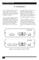
A/C-7P RO, A/C-7S RO 2.1 Description of Front Panels CONFIGURATION SWITCHES The Configuration Switches are used to set the output protocol and to perform the available test and diagnostic functions. While the A/C7P RO models come with only one bank of switches, the A/C-7S RO comes with two banks of eight switches. The left bank is labeled SW1; the right bank is labeled SW2. • Power—The A/C-7 RO is powered on. On/Off Switch—The On/Off switch is used to power on or power off the A/C-7 RO.
A/C-7P RO, A/C-7S RO The package should include the following: • A/C-7P RO or A/C-7S RO • Wallmount transformer (9V AC output) • Standard parallel cable (for A/C-7P RO only) • Standard serial cable (for A/C-7S RO only) 12
A/C-7P RO, A/C-7S RO 3. Installation Before connecting the A/C-7 RO to the printer, verify that the printer functions properly by performing a printer self-test. Consult the printer’s user’s guide for instructions on how to start and evaluate the self-test. If the printer functions properly, proceed with the installation of the A/C-7 RO. WARNING Electrical current from power lines and cables connecting the A/C-7 RO, printer, and PC can be hazardous. To minimize the danger, follow the instructions below.
A/C-7P RO, A/C-7S RO NOTE Whenever the printer is powered off, the A/C-7P RO must also be powered off to ensure they stay in sync with each other. To install the A/C-7S RO: 1. Power off the printer and PC (if used) and disconnect the power cord(s). 2. Use the configuration switches on the A/C-7S RO’s front panel to select the desired output protocol and the serial output parameters for the interface. Refer to Tables 4.1 and 4.5 for configuration switch settings. 3.
A/C-7P RO, A/C-7S RO 9. With the A/C-7S RO powered off, attach the coax cable from the host to the A/C-7S RO’s BNC connector. NOTE Whenever the printer is powered off, the A/C-7S RO must also be powered off to ensure they stay in sync with each other. To power on: 1. Turn on the printer. 2. Turn on the A/C-7 RO. To power off: 1. Turn off the A/C-7 RO. 2. Turn off the printer. The self-test printouts in Figures 31 and 3-2 show the default settings for the different A/C-7 RO models.
A/C-7P RO, A/C-7S RO Self-Test Printout - A/C-7P RO PARALLEL 3270 COAX INTERFACE COPYRIGHT (c) 1994 SDE Corp Rom Ok Ram Ok Software Version 1.
A/C-7P RO, A/C-7S RO Self-Test Printout - A/C-7S RO SERIAL 3270 COAX INTERFACE COPYRIGHT (c) 1994 SDE Corp Rom Ok Ram Ok Software Version 1.
A/C-7P RO, A/C-7S RO #65 #76 #77 #78 #79 #56 SP: #57 HP: Character Set Selection Serial In Baud Rate Serial In Word Length Serial In Stop Bits : Serial In Parity Parallel Port Init String: : : : 1 Bit : 1 Roman 8 2 9600 Baud 8 Bits 0 None Host Port Init String: Figure 3-2. Self-Test Printout for A/C-7S RO, Page 1 (continued).
A/C-7P RO, A/C-7S RO SCS (LU1) EBCDIC to ASCII Translate Table EBCDIC 0 1 2 3 4 5 6 7 8 9 A B C D E F 40 50 20 26 20 C5 C0 C1 CC CD C8 C9 C4 D5 E2 D1 D4 DD B5 D9 B7 DE BF 21 2E 24 3C 2A 28 29 2B 3B 7C 5E 60 2D 2F A2 D8 A1 E0 E1 D0 B4 B6 7C 2C 25 5F 3E 3F 70 80 D6 D2 DC 61 A4 62 A5 63 A3 64 E5 65 A6 66 A7 67 E6 68 A9 69 3A FB 23 FD 40 E4 27 B2 3D F0 22 FE 90 B3 6A 6B 6C 6D 6E 6F 70 71 72 F9 FA D7 20 D3 BA A0 F3 7E 73 74 75 76 77 78 79 7A B8 B9 E3 B1 F1 20 B0 C0 D0 E0 F0 456789ABCDEF 5E 7B 7D 5C 30 &–øØ
A/C-7P RO, A/C-7S RO 4. Configuration 4.1 A/C-7 RO Configuration The A/C-7 RO can be configured through its on-board configuration switches or by sending download commands from the host or from a PC/LAN. To ensure proper functioning of your A/C-7 RO, you should review all available parameters.
A/C-7P RO, A/C-7S RO 4.2 Configuration Switch Settings Use the A/C-7 RO’s configuration switches to select the output protocol and to perform the available test and diagnostic functions. Use a pointed object, such as a ball-point pen, to change the switch settings. NOTE If an invalid switch setting is encountered at power-up, all LED lights will blink and the A/C-7 RO cannot operate. When operating, the A/C-7 RO will only recognize EBCDIC Hex Dump and ASCII Dump settings.
A/C-7P RO, A/C-7S RO Table 4-1. Configuration Switch Settings.
A/C-7P RO, A/C-7S RO Table 4-2. Tests/Diagnostic. Tests/Diagnostic SW1:1 SW1:8 Restore Factory Defaults | o Self-Test o | EBCDIC Hex Dump o | Table 4-3. Tests/Diagnostic. Tests/Diagnostic SW1:4 SW1:5 SW1:6 SW1:7 ASCII Hex Dump | | | | Table 4-4. Operating Mode.
A/C-7P RO, A/C-7S RO The second (right) bank of switches of the A/C-7S RO is used to set up the A/C-7S RO for communication with the printer. Table 4-5. Serial Out Baud-Rate Switches.
A/C-7P RO, A/C-7S RO Table 4-6. Serial Out Word-Length Switch. Serial Out Word Length SW2:4 7 Bits o 8 Bits | Table 4-7. Serial Out Stop Bits Switch. Serial Out Stop Bits SW2:5 1 Bit o 2 Bits | Table 4-8. Serial Out Parity Switch. Serial Out Parity SW2:6 SW2:7 None o o Odd o | Even | 0 Table 4-9. Serial X-On/X-Off Switch.
A/C-7P RO, A/C-7S RO 4.3 Setup Software (does not apply to versions after February 1996) Older versions of the A/C-7 RO included a setup disk. For newer versions (after February 1996), all configuration parameters not already covered through configuration switches can be changed through the host/PC download commands. NOTE For a description of the available configuration parameters, refer to the Table 4-11, Host/PC Download Commands. 4.
A/C-7P RO, A/C-7S RO 1. Type the Command Pass-Thru delimiter &% (or alternate CPT beginning delimiter) in the document at the point where the command is to take effect. 2. Type an upper case “Z” (or the alternate command ID character). 3. Type the command number for the command to be used, as shown in the table. 4. Type a comma. 5. Type the value representing the desired selection. No spaces are allowed.
A/C-7P RO, A/C-7S RO Table 4-11. Host/PC Download Commands. 28 Host/PC Download Command Command Number 10 CPI Command String 86 12 CPI Command String 88 15 CPI Command String 87 16.
A/C-7P RO, A/C-7S RO Table 4-11 (continued). Host/PC Download Commands.
A/C-7P RO, A/C-7S RO Table 4-11 (continued). Host/PC Download Commands.
A/C-7P RO, A/C-7S RO Table 4-11(continued). Host/PC Download Commands.
A/C-7P RO, A/C-7S RO Asterisks (*) identify factorydefault settings. Invalid commands (such as selecting 2 LPI) are ignored. The last valid setting will be unchanged. Examples in this section apply to configuration through Host/PC download only. COMMAND 1: BUFFER SIZE COMMAND 2: LINES PER INCH Selects default LPI. VALUE 3 4 *6 8 Selects logical default buffer size.
A/C-7P RO, A/C-7S RO COMMAND 4: LINE SPACING COMMAND 6: MAXIMUM PRINT POSITION Selects default Line Spacing. VALUE *1 2 DESCRIPTION Single Space Double Space Example: &%Z4,2 sets the printer to double space default. COMMAND 5: FORM LENGTH Selects default Form Length (MPL = Maximum Print Lines).
A/C-7P RO, A/C-7S RO COMMAND 7: PRINT CASE Selects default print case. VALUE 0 *1 DESCRIPTION Mono case Dual case NOTE This default only affects LU3 printing. 23 (same as 07) 24 (same as 09) 25 (same as 01) 26 (same as 08) 27 (same as 10) 28 29 (same as 06) 30 (same as 11) Example: &%Z7,0 sets default to mono case. COMMAND 8: LU1 LANGUAGE Selects default LU1 language. VALUE * 01 DESCRIPTION English (U.S.
A/C-7P RO, A/C-7S RO COMMAND 9: EPSON MATRIX FONT Selects Epson default font, if supported by the printer. VALUE *1 2 3 4 5 6 7 DESCRIPTION Draft Print Quality Roman, NLQ Sans Serif, NLQ Courier, NLQ Prestige, NLQ Script, NLQ OCR-B, NLQ Example: &%Z9,2 selects near-letter quality (Roman) as the default.
A/C-7P RO, A/C-7S RO command in the SCS PPM causes the printer to wait for the operator to insert paper in the manual feed tray. This command takes effect immediately if placed on the first position of the page (line 1, position 1); otherwise, it takes effect on the next page. Example: &%Z11,5 selects manual sheet feed as the default source of paper. COMMAND 13: FORM FEED AFTER LOCAL SCREEN COPY Specifies whether a form feed is performed after a local screen hard copy.
A/C-7P RO, A/C-7S RO 1 2 True screen image in nonSCS print and null-line suppression in local copy 3 True screen image in nonSCS print and true screen image in local copy NOTES To use this function, the RPQ should be: IBM 3268 RPQ SC9505 IBM 3287 RPQ SC3741 IBM 4214 OPT 18=2 Available only in LU3 (nonSCS) operations. Values 0 and 1 are only functional from CUT terminals. Example: &%Z14,3 prints true screen image in non-SCS print and local copy.
A/C-7P RO, A/C-7S RO COMMAND 17: VALID FF FOLLOWED BY DATA NOTES To use this function, the RPQ should be: IBM 3268 RPQ SC9504 IBM 3287 RPQ SC3749 IBM 4214 OPT 17=2 Sets the printer in accordance with the RPQ installed in the control unit.
A/C-7P RO, A/C-7S RO COMMAND 20: AUTOMATIC FUNCTION AT END OF JOB COMMAND 21: PRINT QUALITY (FastDraft) Sets the printer in accordance with the RPQ installed in the control unit. Defines default print quality. VALUE *0 DESCRIPTION NL is automatically executed after the buffer is completed (unless a FF, NL, or CR was last in the buffer). 1 FF is automatically executed after the print buffer is completed (unless a FF was last in the buffer).
A/C-7P RO, A/C-7S RO COMMAND 25: IBM MOTION COMMANDS Enables a Form Feed from the host system to be converted to the required number of line feeds (beneficial when forms length is controlled by the interface). VALUE *0 DESCRIPTION Pass FF from host to the printer 1 Count the lines in Command 5 and send multiple line feeds to the printer in place of the host FF 2 Ignore all IBM Motion Commands Example: &%Z25,1 sets the printer to count the lines specified in Command 5.
A/C-7P RO, A/C-7S RO COMMAND 30: OVERRIDE OF FORMATTING COMMANDS COMMAND 31: TRUNCATE/WRAP SELECT Enables the printer’s front-panel selections to control how a job is printed. Printers without HP PCL only. Selects whether the interface truncates or wraps the text if the maximum print position is exceeded.
A/C-7P RO, A/C-7S RO COMMAND 34: INTERVENTION REQUIRED (IR) TIMEOUT NOTES If this command is set to 1, documents need to be formatted by sending transparent control codes to the printer using Command Pass-Thru or SCS mode transparent data. Sets the time interval before an intervention required signal is sent to the host after a printer error occurs. VALUE 000 DESCRIPTION Never send an IR 001 to 255 IR is sent (value *5) seconds after printer error occurs *120 Default, send IR after ten minutes.
A/C-7P RO, A/C-7S RO COMMAND 38: TRUE LPI SPACING COMMAND 39: CPT ENDING DELIMITER CHARACTERS HP PCL only. Because laser printers have a non-printable border around the edge of single-sheet pages, 6 LPI and 8 LPI spacing is compressed slightly to enable 66 lines and 88 lines to be printed on 11-inch long paper. This can occasionally cause a problem, especially when using preprinted forms that must align precisely. Command 38 enables a user to override the laser-printer LPI compression.
A/C-7P RO, A/C-7S RO COMMAND 40: CPT START DELIMITER CHARACTERS Specifies the two characters to be used for the beginning delimiter characters for Command Pass-Thru. VALUE XXYY DESCRIPTION XX is the ASCII hexadecimal value of the first character and YY is the ASCII hexadecimal value of the second character NOTES Host download commands use the CPT beginning delimiter characters as well. The new character(s) replace the &% in front of the Z.
A/C-7P RO, A/C-7S RO COMMAND 42: START AND STOP EBCDIC HEX DUMP COMMAND 45: SCS TRN TRANSLATE After receiving a start command the coax interface, starting with the next buffer received, sends all host data directly to the printer as hexadecimal printing until a stop command is received or the printer is powered off. Specifies how transparent data sent using SCS code 35 is handled.
A/C-7P RO, A/C-7S RO Use of the DOS PRINT command or a spooling program for the PC is recommended. COMMAND 50: SHARING PORT TIMEOUT Selects the time interval that the interface waits for receipt of additional data from the alternate (PC/LAN) host before automatically switching to check for data from the coax host.
A/C-7P RO, A/C-7S RO COMMAND 55: CUSTOM USER STRINGS COMMAND 56: PARALLEL PORT INITIALIZATION STRING Allows the user to define up to six custom user strings, of up to 25 bytes each, which are stored in the memory of the interface and sent to the printer whenever the character delimiter, letter U, and number of the string appears in the text of the document (for example, &%U3).
A/C-7P RO, A/C-7S RO COMMAND 57: HOST PORT INITIALIZATION STRING Allows the user to define an initialization string of up to 25 bytes, which is stored in the memory of the interface and is sent to initialize the printer for host printing after shared-port printing has occurred. The interface also restores the host page-format parameters after sending this string and prior to host printing. The initialization string is sent at the beginning of each page. VALUE 1(max.
A/C-7P RO, A/C-7S RO To change the initialization string, simply input the new command values. The entire old string is automatically erased. NOTE APO active is the recommended selection. A user can manipulate the page dimensions using SCS commands to control the orientation of the printing as long as the page size required is 8 1/2 x 11" or smaller. To delete the initialization string from the NV memory, simply put nothing between the parentheses.
A/C-7P RO, A/C-7S RO 3 User Defined mode. Documents are printed using the fonts and orientation that the user specifies through use of the &% font ID commands. Example: &%Z62,3 specifies that the document is printed as formatted when the primary paper tray is specified as the paper source. COMMAND 63: ALTERNATE PAPER TRAY ORIENTATION HP PCL only. This command functions identically to Command 62 except it controls the orientation for printing that specifies the alternate tray for the paper source.
A/C-7P RO, A/C-7S RO character-set selection is changed. Example: &%Z64,1 specifies that all printing using paper from the manual feed slot will be printed in portrait orientation. Refer to the character set summary tables at the end of the self test to confirm which ASCII character is printed for each of the 3270 hex codes. Both the EBCDIC and DSC tables are provided.
A/C-7P RO, A/C-7S RO Previously stored substitutions are cancelled if an ASCII hex sequence of 00 is specified. Command Z99,0 must be used to store the substitutions in permanent memory for them to be effective when the printer is next turned on. The active EBCDIC (SCS/LU1) translation table prints out at the end of the interface self-test summary. Example: &%Z70,7B,40/Z99,0 prints a 40 ASCII hex (a @ symbol) when the interface receives an EBCDIC 7B (a # symbol).
A/C-7P RO, A/C-7S RO COMMAND 77: SERIAL-IN WORD LENGTH COMMAND 79: SERIAL-IN PARITY Selects the Word Length of data received at the serial-in port. A new setting will not be effective immediately. To activate the new setting, cycle power on the interface. Selects the Parity of a data stream received at the serial-in port. A new setting will not be effective immediately. To activate the new setting, cycle power on the interface.
A/C-7P RO, A/C-7S RO NOTES This string represents the printer-specific command to set the printer to 6 LPI. Consult your printer’s manual for the appropriate hex value representing the 6 LPI command. Example: &%Z84,1(1B 32) stores the 6 LPI command for an Epson LQ-2500 printer (hex value 1B 32) as the 6 LPI string. COMMAND 85: 8 LPI STRING Used when operating in Generic output protocol. Defines the 8 LPI string the interface sends to the printer when the host sends an 8 LPI command. VALUE 1(max.
A/C-7P RO, A/C-7S RO COMMAND 87: 15 CPI STRING COMMAND 89: 16.7 CPI STRING Used when operating in Generic output protocol. Defines the 15 CPI string the interface sends to the printer when the host sends a 15 CPI command. Used when operating in Generic output protocol. Defines the 16.7 CPI string the interface sends to the printer when the host sends a 16.7 CPI command. VALUE 1(max. 25 bytes of ASCII hex code) 1() DESCRIPTION Defines the 15 CPI string Deletes the 15 CPI string VALUE 1(max.
A/C-7P RO, A/C-7S RO NOTES If a document is printed using temporary host download commands (commands not stored using the Z99,0 command), value 2 will restore the permanent memory selections. Put a &%Z98,2 at the end of the document to restore the standard setup parameters for the next user of the printer. The active setup and permanent memory setup selections are the same after a Command Z99,0 or a Command Z98,2 is sent to the printer. Example: &%Z98,1 prints out the active setup selections for review.
A/C-7P RO, A/C-7S RO 4.5 Restoring Factory Defaults The factory-default configuration can be restored either by sending Host/PC Download Command “Z98,0” or by taking the following steps: 1. Power off the printer and the A/C-7 RO. 2. Disconnect the host and PC sharing cables from the interface. 4. Power on the A/C-7 RO. The factory defaults are restored. The LED lights labeled “Host Ready” and “Printer Ready” will blink continuously, indicating the A/C-7 (RO) is not in operating mode. 5.
A/C-7P RO, A/C-7S RO 5. Operation 5.1 Printer Sharing The A/C-7P RO and A/C-7S RO allow the printer to be shared automatically between an attached PC/LAN and an IBM coax host. Simply connect the PC/LAN printer server to the parallel/serial port. The A/C-7P RO can supply external devices attached to its parallel sharing port with 5V up to 350 mA. See Appendix E for instructions on how to transfer power to pin 18 on the A/C-7P RO.
A/C-7P RO, A/C-7S RO PC printing longer than 10 to 20 minutes (depending on host configuration) may cause the 3270 host to drop communication with the printer (“go to sleep”). The output protocol specified in the A/C-7S RO’s configuration (through configuration-switch settings) is irrelevant for printing from the shared port. For PC/LAN printing, select the appropriate printer driver on the PC/LAN printer server. 5.
A/C-7P RO, A/C-7S RO Table 5-1. PMPP and PMPL. PMPP at 10 12 CPI CPI 15 CPI PMPL at 17.1 6 CPI LPI 8 LPI True LPI True LPI Letter Portrait Landscape COR 80 105 136 96 126 154 120 157 201 136 178 201 66 50 66 88 87 89 63 48 — 84 84 — Legal Portrait Landscape 80 135 96 162 120 202 136 230 84 50 112 67 81 48 108 64 A4 Portrait Landscape 78 112 93 134 117 167 133 191 70 49 93 66 67 47 89 62 Paper Size 5.
A/C-7P RO, A/C-7S RO For example: &%L00086 selects a Prestige 12 CPI font in landscape orientation. The font ID number must select a font available in the printer or in the installed cartridge. If the proper cartridge is not installed, or the font does not exist on the cartridge, then the printer will automatically select an alternate font for printing. Multiple font changes can be made in a document as long as all fonts are in the same orientation.
A/C-7P RO, A/C-7S RO A combination of control codes in the printer data stream and the settings in the configuration are used to determine page orientation when processing DSC, DSE, or LU1 (SCS) data streams. Some applications will not allow you to insert the data stream commands required to select orientation and format. Where the insertion of the required data stream commands is not possible, you can select the orientation and format desired by using the printer configuration settings.
A/C-7P RO, A/C-7S RO START Page Orientation Logic 1 APO Active? (Command 61) No Print according to Paper Tray Orientation (Commands 62-64) Yes 2 COR Print Size Less Than 8 1/2 x 11? Portrait Landscape No User Defined Yes 3 Is Length Less Than Width? No Print in Portrait Print in Landscape Figure 5-1. Printing with the APO Feature.
A/C-7P RO, A/C-7S RO 5.8 Generic Mode The Generic output protocol should be used when the other output protocols of the A/C-7 RO are inappropriate. This could be the case with printers such as certain barcode label printers or embossers, but also with printers from Okidata®, Mannesmann-Tally®, etc. Refer to the printer’s user’s guide to find out if the printer operates with one of the output protocols of the A/C-7 RO. In Generic mode, the A/C-7 RO does not pass on the LPI and CPI commands from the host.
A/C-7P RO, A/C-7S RO Table 5-2. Commands. Command Function ¬E Sends an ASCII ESC command to the printer ¬TY Enables true LPI printing ¬TN Disables true LPI printing ¬I Ignores all host formatting commands ¬S Stops ignoring host formatting commands The ¬E command allows you to send an escape command to the printer to control the printing. For example, ¬E(s3B would begin bold printing (see your printer’s manual for a list of the printer or escape commands).
A/C-7P RO, A/C-7S RO 6. Advanced Features There are several advanced features in the A/C-7 RO for accessing special functions of the printers, which are not normally available on the IBM system printers: • Command Pass-Thru™ • Custom User Strings • SCS Mode Transparent Data • Bar Code Printing • Color Printing • I-O Graphics Language™ Each of these features is described below. 6.
A/C-7P RO, A/C-7S RO This is an &%1B26643044&%underlined&%1 B266440&% word. For example, use command 55 to define user string number 3 to send a form feed as follows (FF = 0C in hex): to print on the printer as: &%Z55,3(0C) This is an underlined word. NOTES Only numbers or the upper case letters A–F are allowed. Errors in the Command Pass-Thru sequence will cause the A/C-7 RO to ignore the command and resume printing at the point the error occurred. Command Pass-Thru may change the horizontal spacing.
A/C-7P RO, A/C-7S RO SCS TRN data is user-defined is not scanned for SCS control codes. However, to emulate the characteristics of the IBM 3287, non-printable characters (control characters) are converted to hyphens. Data is translated to ASCII with undefined characters printed as hyphens. The A/C-7 RO offers a configurable option to emulate the IBM 3287 or to pass the data without translation. Refer to command 45, SCS TRN translate, on page for more detailed information. 6.
A/C-7P RO, A/C-7S RO The bar-code command string must contain all of these parameters, even if the parameter is irrelevant for the type of bar code being printed. For example, POSTNET comes in only one size, so, any height or width specifications are ignored. But the parameters for height and width must be included anyway. : Specifies the width of a bar code module. A module is defined as a specific combination of bars and spaces used to represent a humanreadable character.
A/C-7P RO, A/C-7S RO Module width (from Table 6-2): 3.6 mm (0.14 inches) Calculation: 11 x 3.6 mm = 39.6 mm = 3.96 cm; or 11 x .14 in = 1.54 inches Table 6-2. Module Width in mm (inches): PCL Laser. Width 1 2 3 4 5 6 7 Code 3 of 9 2.6 (.1) 3.6 (.14) 4.5 (.18) 5.5 (.22) 6.5 (.25) 7.5 (.29) 8.4 9.4 (.33) (.37) 10.4 (.41) Code 128 2.2 (.09) 3.1 (.12) 3.9 (.15) 4.7 (.19) 5.6 (.22) 6.4 (.25) 7.3 8.1 (.29) (.32) 8.9 (.35) Interleaved 2 of 5 2.3 (.09) 3.2 (.12) 4 (.16) 4.9 (.19) 5.
A/C-7P RO, A/C-7S RO Table 6-3. Module width in mm (inches): Epson or IBM Proprinter Dot-Matrix. Width 1 2 3 Code 3 of 9 2.7 (.11) 5.4 (.22) 8.1 (.32) Code 128 2.5 (.1) 5 (.2) 7.6 (.3) Interleaved 2 of 5 2.2 (.9) 4.4 (.18) 6.6 (.26) POSTNET 6.5 (.25) EAN 13 1.5 (.06) 3.1 (.12) 4.6 (.18) EAN 8 1.8 (.07) 3.6 (.14) 5.5 UPC A 1.8 (.07) 3.6 (.14) 5.5 (.
A/C-7P RO, A/C-7S RO Width parameters are ignored when printing POSTNET bar codes, since POSTNET uses one standard width. However, a valid value (1-9) must be entered for the width parameter to ensure the bar code command string is complete.
: Identifies whether humanreadables are printed or not. Human-readables are printed underneath the bar code. Valid values are: 0 = Do not print human readables. 1 = Print human readables.A/C-7P RO, A/C-7S RO : The data to be printed as a bar code. Some bar codes require a certain number of characters. Others only allow alphanumeric or numeric characters. Before the A/C7 RO processes the data string, it will check the complete data string and verify that it is valid. This is why the ¬B at the end is so important. If an invalid data string has been entered, the A/C-7 RO will print “Invalid Data” in the place of the bar code. NOTES 1.
A/C-7P RO, A/C-7S RO This data overrun by barcode Figure 6-1. Bar Code Overlapping Text. To avoid overlapping bar codes with text, always allow for sufficient vertical line spacing (by adding line feeds, for example) to accommodate the height of the bar code. 6. When text data is entered to the right of the bar code command sting, the printed text will appear immediately to the right of where the barcode print ends.
A/C-7P RO, A/C-7S RO OVERVIEW AND EXAMPLES The examples shown on the following pages give an overview of the supported bar code types. Note that the “maximum number of data characters” does not include start/stop characters and check digits. Code 3 of 9 Maximum number of data characters: Valid numeric characters: Valid alphanumeric characters: Valid other characters: 30 0-9 A-Z space ! “ # $ % & ‘ ( ) + , - . / : ; < =>?@ Example: ¬B1,4,1,1,1,1,0123456789¬B 0123456789 Figure 6-2. Code 3 of 9.
A/C-7P RO, A/C-7S RO UPC A Required number of data characters: Valid numeric characters: Valid alphanumeric characters: Valid other characters: 10 0-9 N/A N/A Example: ¬B5,5,1,1,1,0,0123456789¬B 0 01234 56789 5 Figure 6-4. UPC A. EAN 8 Required number of data characters: Valid numeric characters: Valid alphanumeric characters: Valid other characters: Example: ¬B6,3,1,1,1,0,1234567¬B 1234 5670 Figure 6-5. EAN 8.
A/C-7P RO, A/C-7S RO EAN 13 Required number of data characters: Valid numeric characters: Valid alphanumeric characters: Valid other characters: 12 0-9 N/A Example: ¬B7,3,1,1,1,0,012345678912¬B 0 123456 789128 Figure 6-6. EAN 13. Interleaved 2 of 5 Maximum number of data characters: Valid numeric characters: Valid alphanumeric characters: Valid other characters: 30 0-9 N/A N/A Example: ¬B3,3,1,1,1,0,0123456789¬B 0123456789 Figure 6-7. Interleaved 2 of 5.
A/C-7P RO, A/C-7S RO NOTE Since Interleaved 2 of 5 symbols are created from data-character pairs, the number to be encoded must have an even number of digits. If an odd number of data characters (including the optional check digit) is entered, the A/C-7 RO adds an “0” to the beginning of the bar code. If an even number of data characters (including the optional check digit) is entered, the A/C-7 RO prints the bar code exactly as it is input.
A/C-7P RO, A/C-7S RO To show how multiple character sets are used, study the following data string. Height, width and other parameters were omitted in this example to focus your attention on the data string. Please note that this example is for illustration purposes only, and is not a recommended way of bar coding. The following data string is a fairly complex way of bar coding “10A/C-7(RO)10”. ¬B2,...
A/C-7P RO, A/C-7S RO Table 6-4. Symbol Character Value and Data Character. 80 Symbol Character Value Code A Data Character Code B Code C 00 01 02 03 04 05 06 07 08 09 10 11 12 13 14 15 16 17 18 19 20 21 22 23 24 25 26 27 SP ! “ # $ % & ‘ ( ) * + . . / 0 1 2 3 4 5 6 7 8 9 : ; SP ! “ # $ % & ‘ ( ) * + . .
A/C-7P RO, A/C-7S RO Table 6-4 (continued). Symbol Character Value and Data Character.
A/C-7P RO, A/C-7S RO Table 6-4 (continued). Symbol Character Value and Data Character.
A/C-7P RO, A/C-7S RO Table 6-4 (continued). Symbol Character Value and Data Character.
A/C-7P RO, A/C-7S RO 6.6 I-O Graphics Language™ The I-O Graphics Language™ (IOGL™) allows printing of graphical elements and charts on PCL5 compatible printers. IOGL is independent of other I-O features, such as internally generated bar codes or font change commands. This means that if an I-O font change command is followed by an IOGL command to rotate text, the text would print in the specified font. IOGL is also independent of regular text data.
A/C-7P RO, A/C-7S RO Table 6-5. IOGL Graphics Language. Graphical Element IOGL Command String Line ¬GL;;; Box ¬GB;;;;; <% shading> Circles ¬GC;;;; <% shading> Arc ¬GA;;;; ; Shading/Color ¬GS<# of values>;;<% shading 1>; ;<% shading 2>;...
A/C-7P RO, A/C-7S RO Table 6-5. IOGL Graphics Language.
A/C-7P RO, A/C-7S RO Table 6-5 (continued). IOGL Graphics Language. Parameter Description Units of Measurement Valid Values radius radius of a circle or pie chart n/300 inch positive integers segment value n value to be represented by a pie chart segment integer 0 to 100 value n a value to be represented by a bar in a bar chart or a point in a line chart any positive integer any positive integer x start x coordinate of start position for lines and boxes n/300 inch positive integers; incl.
A/C-7P RO, A/C-7S RO Table 6-5 (continued). IOGL Graphics Language. Parameter Description Units of Measurement Valid Values y start y coordinate of start position for lines and boxes n/300 inch positive integers; incl. 0 y end y coordinate of end position for lines and boxes n/300 inch positive integers; incl. 0 y increment height of one unit of the value to be printed in bar or run (line) chart n/300 inch positive integers; incl. 0 6.6.2 HELPFUL HINTS 1.
A/C-7P RO, A/C-7S RO Physical Page X X,Y origin (0,0) Physical Page X Printable Area X X,Y origin (0,0) Printable Area X Y Y Figure 6-9. XY Coordinate System on the Page. 2. The complete command string must be entered as shown below. Incomplete command strings and command strings with invalid values (such as spaces) will cause the A/C-7 RO to print the string at the place where the error occurred. For example, a line command string has been entered.
A/C-7P RO, A/C-7S RO 6.6.3 BASIC DESCRIPTION Lines—¬GL;;;; Draws a line from the specified xy start to xy end. is specified in mm. For example: ¬GL2;100;0;100;600 draws a 2 mm wide, vertical ( = ) line of 2 inches in length ( - = 600/300” = 2”) (Figure 6-10) X,Y start (100,0) 2 inches X,Y end (100,600) Figure 6-10. Example of Line.
A/C-7P RO, A/C-7S RO Boxes—¬GB;;;;;<% shading>6 is specified in mm; <% shading> can range from 0 to 100. Draws a box from the specified xy start to the xy end. The box cannot be rotated. For example: ¬GB2;300;300;600;600;30 draws a box with 2 mm wide border and 30% shading (Figure 6-11). X,Y start (300,300) Line width = 2mm X,Y end (600,600) 30% shading Figure 6-11. Example of Box.
A/C-7P RO, A/C-7S RO Circle—¬GC;;;;<% shading> For example: ¬GC2;900;2400;300;70 draws a circle with a radius of 1 inch (300/300 inches) (Figure 6-12) Draws a circle with the specified radius (in n/300 inches) and line width (in mm) around the xy center. NOTE To avoid cutting off part of the circle, make sure that the radius and the x,y center values are such that the complete circle will fit into the printable area of the page.
A/C-7P RO, A/C-7S RO Arc—¬GA;;;;; For example: ¬GA1;500;900;900;900;180 draws an arc (semi-circle since rotation is 180 degrees) (Figure 6-13) Draws an arc around the xy center, starting at xy start and ending when the angle of rotation is completed. (Angle is measured from theoretical line xy center to xy start and rotates clockwise.) 180° X,Y start (500,900) X,Y center (900,900) Figure 6-13. Example of Arc.
A/C-7P RO, A/C-7S RO Color/Shading—¬GS<# of values>;;<% shading 1>;;<% shading 2>;... Defines the color and shading of the pie-chart and bar-chart segments. The first value entered in the pie and bar chart commands will be printed in color 1 with shading 1. The second value entered in the pie and bar chart commands will be printed in color 2 with shading 2. Colors are entered as numeric values 0-16 (corresponding to color command scheme).
A/C-7P RO, A/C-7S RO “9 o’clock” = starting point for first pie segment Figure 6-14. Color/Shading and Pie Chart.
A/C-7P RO, A/C-7S RO For example: ¬GS3;01;20;02;50;04;80 ¬GP5;900;2400;600;3;10;20;30 draws a three-segment pie chart. If the attached printer is a PCL color printer, the first segment will be blue (01), the second segment will be red (02), and the third segment will be green (04). The segments will be shaded at 20%, 50%, and 80% respectively.
A/C-7P RO, A/C-7S RO Bar Chart (Histogram)—¬GH;;;;;;<# of entries>; ;; ... Draws a bar chart. xy start specifies the bottom left hand corner of the first bar (the origin on the chart’s xy scale). The x increment specifies the horizontal movement before the next bar is printed. The y increment (in n/300 inches) determines the height of the bar (multiplied by the value).
Ba Co r 1 ( Sh lor: valu ad Re e 5 ing d* 00 ) :5 0% Ba Co r 1 ( Sh lor: valu ad Gr e 5 ing ee 00 ) : 8 n* 0% Ba Co r 1 ( Sh lor: valu ad Blu e 5 ing e* 00 ) :2 0% A/C-7P RO, A/C-7S RO Line width 5mm Height = value times (*) y increment X,Y start (100,2400) x increment = horizontal distance between values Figure 6-16. Bar Chart (Histogram). Each bar is 1/3 inch wide (100/300 inch). The distance from the left side of one bar to the left side of the next bar is one inch (300/300).
A/C-7P RO, A/C-7S RO Run Chart—¬GR;;;;;<# of entries>;;; ... For example: ¬GR3;900;2400;150;1;5;100;300;200; 500;400 draws a run (line) chart (Figure 6-17). Draws a run (line) chart. The xy start specifies the origin of the chart’s xy scale (xy axes are not drawn). The x increment specifies the horizontal movement before the next value is printed. The y increment determines the height of the line (multiplied by the value).
A/C-7P RO, A/C-7S RO NOTE Prints the text (“text”) in the active font, with the specified rotation and specified xy start. Text will be rotated counterclockwise. For example: ¬GT1000;1000;90;’TEXT’ prints the word 'TEXT' in the active font with 90 degree rotation (Figure 6-18). TEXT The y-increment determines the scaling. Only integers (1, 2, 3, 4, etc.) are valid. If you are charting sales figures in thousands of dollars, the yincrement should be small (for example, 1).
A/C-7P RO, A/C-7S RO Comments—¬GX<'text'> Allows text to be added to IOGL commands for documentation. Comments will not print out. For example: ¬GX’Pie chart with 3 elements’ can be used to document an IOGL pie chart command. 6.7 I-O Graphics Language™ (IOGL) in Action 6.7.1 GENERAL STEPS I-O Graphics Language™ (IOGL) can be used in many different ways.
A/C-7P RO, A/C-7S RO SALES CALLS PER DAY Week of: March 24, 1995 # OF CALLS BOYD 40 GARY SHAWN 30 20 10 Monday Tuesday Wednesday Thursday Friday WEEKDAY Figure 6-19. Bar Chart. 1. Following the above mentioned general steps, we first determined the makeup of this bar chart. The example consists of four IOGL elements: bar charts, lines, boxes, and text. 102 2. To determine the printable area of the paper, we printed a box using 0;0 as the x;y starting coordinates.
A/C-7P RO, A/C-7S RO Approximate Area of Bar Chart 1 inch 4 inches 10 inches 3. Determine where the chart should be placed (always in relation to the top left-hand corner of the printable area). In the example, the bar chart is on the bottom half of a letter-size page. The origin of the chart is one inch away from the left margin and 10 inches away from the top margin (Figure 6-20). 5 inches Origin of Chart Figure 6-20. Placement of Bar Chart.
A/C-7P RO, A/C-7S RO Next, determine the approximate maximum height and width of the chart. In the example, 40 was the expected maximum number of calls. We chose to represent 10 calls by one inch, resulting in a total maximum height of four inches (not including the title and subtitle.) Similarly, each day was represented by one inch, resulting in a total maximum width of five inches (not including the space needed for the label “WEEKDAY”). 4.
A/C-7P RO, A/C-7S RO one and the first bar of the next day. To determine the , divide the available one inch () into four equal sections (three bars and one space). The resulting value was 75 (= 300/4). Next, count the <# of entries> (5) and enter the respective values.
A/C-7P RO, A/C-7S RO 6.7.4 LABELS/TITLE/SUBTITLE/LEGEND All text was created through text rotation command strings. Text was always printed in the selected font. In the example, Universe Medium was used in different point sizes (¬Q...). The legend consists of three separate boxes followed by text rotation commands.
A/C-7P RO, A/C-7S RO For the # symbol, substitute a number that identifies the macro. Make sure this command precedes all IOGL commands. Also, be aware that PCL is case-sensitive. At the end of the IOGL routine, stop the macro and save it permanently (until the printer is powered down) in the printer’s memory. To end the macro, type: ¬E&f#y1X To save the macro permanently (until the printer is powered down) type: ¬E&f#y10X. Store this macro in the printer’s memory by “printing” it.
A/C-7P RO, A/C-7S RO A PCL command used to reposition the stored image on a page is ¬E&l#u#Z, where the first # (l#u) specifies the “Left Offset Registration” or horizontal movement in n/720 inch and the second # (#Z) specifies the “Top Offset Registration” or vertical movement of the image in n/720 inch. The repositioning command must precede the macro call. To return to the original position, type ¬E&l0u0Z immediately after the macro call.
A/C-7P RO, A/C-7S RO 7. Troubleshooting This chapter provides instructions for performing diagnostic tests on the A/C-7 RO. It also contains a problem resolution guide that describes common problems with the A/C-7 RO or the printer and their solutions. If you are unable to solve a problem by following the procedures outlined in this chapter, contact technical support.
A/C-7P RO, A/C-7S RO Follow the steps below to start the self-test from your PC or terminal. 1. Verify that the printer is connected properly to the A/C-7 RO and in “READY” mode. 2. Type “&%Z98,1” on the screen. 3. Send that command to the printer (press the Print Screen Button or print the document/file that contains the Host/PC download command). The self-test will print out in a few seconds. Follow the steps below to start the self-test by setting the configuration switches. 1.
A/C-7P RO, A/C-7S RO 3. Send that command to the printer (press the Print Screen Button or print the document/file that contains the Host/PC download command). 4. Send the host data in question to the printer. 5. To stop the EBCDIC hex dump, type “&%Z42,2” on the screen, then send it to the printer (press the Print Screen Button or print the document/file that contains the Host/PC download command). Start the EBCDIC hex dump from the A/C-7 RO’s front panel as follows: 1.
A/C-7P RO, A/C-7S RO 7.4 Problem Resolution Guide The following is a general guide to resolve common problems that may occur. Please refer to this guide before contacting technical support. Table 7-1. Problem Resolution Guide. Problem or Message Probable Cause Action “Host Line Sync” LED is not on when connected to the host Host is not operating Check host system. Damaged or improper cabling Check host cabling for damage or improper connection.
A/C-7P RO, A/C-7S RO Table 7-1. Problem Resolution Guide. Problem or Message Probable Cause Action Right margin is cut off Page width in wordprocessing program is not set wide enough Change to a wider page. Page width is too wide Select a narrower page. Form length not correct in software (maximum length is 66 lines) Make sure your document length doesn’t exceed the maximum number of lines.
A/C-7P RO, A/C-7S RO Table 7-1. Problem Resolution Guide. Problem or Message Probable Cause Action Printer won’t change fonts Incorrect typestyle number Make sure the font ID used is valid. Invalid font IDs are ignored by the printer. Wrong font cartridge loaded Load the cartridge with the font that corresponds to the font ID. Font cartridge damaged or not seated into the printer properly If possible try a known good cartridge to determine if cartridge is faulty.
A/C-7P RO, A/C-7S RO Table 7-1. Problem Resolution Guide. Problem or Message Printer does not print portrait in requested font Probable Cause Action APO feature is OFF and orientation is set to COR, portrait, or user-defined (with font orientation portrait) Set paper tray orientation to landscape or set font orientation to landscape or set font orientation to landscape.
A/C-7P RO, A/C-7S RO Table 7-1. Problem Resolution Guide. Problem or Message Probable Cause Action Printer does not print COR APO feature is ON and page size is 8-1/2" x 11" or less Turn off APO or increase page size so it is larger than 8-1/2" x 11". APO feature is OFF and orientation is set to portrait, landscape, or user-defined Set orientation to “COR.
A/C-7P RO, A/C-7S RO Appendix A: Font (FGID) Reference for HP LaserJet Printers The following table lists the standard HP LaserJet resident fonts and the HP font cartridges that are available, along with the font ID number used to select the font. Table A-1. Selecting Standard Fonts. Typeface Symbol Set Orient. Pitch Point Size Typestyle No. HP LaserJet Internal Resident Fonts Courier R-8/CP850 P/L 10 12 11 Line Printer R-8/CP850 P/L 15 8.5 223 Line Printer R-8/CP850 P/L 17.1 8.
A/C-7P RO, A/C-7S RO Table A-1 (continued). Selecting Standard Fonts. Typeface Symbol Set Orient. Pitch Point Size Typestyle No. Courier R-8/CP850 P/L 12 10 85 Courier bold R-8/CP850 P/L 12 10 88 Courier italic R-8/CP850 P/L 12 10 89 Letter Gothic R-8/CP850 P/L 12 12 87 LaserJet III and IIISi Resident Scalable Fonts CG Times 118 R-8/CP850 P/L Prop. 6 4605 R-8/CP850 P/L Prop. 8 4606 R-8/CP850 P/L Prop. 10 4607 R-8/CP850 P/L Prop.
A/C-7P RO, A/C-7S RO Table A-1 (continued). Selecting Standard Fonts. Typeface Orient. Pitch Point Size Typestyle No. CG Times bold R-8/CP850 P/L Prop. 6 4625 R-8/CP850 P/L Prop. 8 4626 R-8/CP850 P/L Prop. 10 4627 R-8/CP850 P/L Prop. 12 4628 R-8/CP850 P/L Prop. 14 4629 R-8/CP850 P/L Prop. 18 4631 R-8/CP850 P/L Prop. 24 4634 R-8/CP850 P/L Prop. 30 4637 R-8/CP850 P/L Prop. 6 4645 R-8/CP850 P/L Prop. 8 4646 R-8/CP850 P/L Prop.
A/C-7P RO, A/C-7S RO Table A-1 (continued). Selecting Standard Fonts. Typeface CG Times bold italic Univers medium 120 Symbol Set Orient. Pitch Point Size Typestyle No. R-8/CP850 P/L Prop. 24 4654 R-8/CP850 P/L Prop. 30 4657 R-8/CP850 P/L Prop. 6 4665 R-8/CP850 P/L Prop. 8 4666 R-8/CP850 P/L Prop. 10 4667 R-8/CP850 P/L Prop. 12 4668 R-8/CP850 P/L Prop. 14 4669 R-8/CP850 P/L Prop. 18 4671 R-8/CP850 P/L Prop. 24 4674 R-8/CP850 P/L Prop.
A/C-7P RO, A/C-7S RO Table A-1 (continued). Selecting Standard Fonts. Typeface Univers med italic Symbol Set Orient. Pitch Point Size Typestyle No. R-8/CP850 P/L Prop. 14 4809 R-8/CP850 P/L Prop. 18 4811 R-8/CP850 P/L Prop. 24 4814 R-8/CP850 P/L Prop. 30 4817 R-8/CP850 P/L Prop. 6 4825 R-8/CP850 P/L Prop. 8 4826 R-8/CP850 P/L Prop. 10 4827 R-8/CP850 P/L Prop. 12 4828 R-8/CP850 P/L Prop. 14 4829 R-8/CP850 P/L Prop. 18 4831 R-8/CP850 P/L Prop.
A/C-7P RO, A/C-7S RO Table A-1 (continued). Selecting Standard Fonts. Typeface Symbol Set Orient. Pitch Point Size Typestyle No. Univers med condensed R-8/CP850 P/L Prop. 6 4845 R-8/CP850 P/L Prop. 8 4846 R-8/CP850 P/L Prop. 10 4847 R-8/CP850 P/L Prop. 12 4848 R-8/CP850 P/L Prop. 14 4849 R-8/CP850 P/L Prop. 18 4851 R-8/CP850 P/L Prop. 24 4854 R-8/CP850 P/L Prop. 30 4857 R-8/CP850 P/L Prop. 6 4865 R-8/CP850 P/L Prop. 8 4866 R-8/CP850 P/L Prop.
A/C-7P RO, A/C-7S RO Table A-1 (continued). Selecting Standard Fonts. Typeface ITC Zapf Dingbat Symbol Set Orient. Pitch Point Size Typestyle No. R-8/CP850 P/L Prop. 24 4874 R-8/CP850 P/L Prop. 30 4877 R-8/CP850 P/L Prop. 6 4985 R-8/CP850 P/L Prop. 8 4986 R-8/CP850 P/L Prop. 10 4987 R-8/CP850 P/L Prop. 12 4988 R-8/CP850 P/L Prop. 14 4989 R-8/CP850 P/L Prop. 18 4991 R-8/CP850 P/L Prop. 24 4994 R-8/CP850 P/L Prop.
A/C-7P RO, A/C-7S RO Table A-1 (continued). Selecting Standard Fonts. Typeface Symbol Set Orient. Pitch Point Size Typestyle No. Time Italic R-8/CP850 P Prop. 10 155 Helvetica Bold R-8/CP850 P Prop. 14.
A/C-7P RO, A/C-7S RO Table A-1 (continued). Selecting Standard Fonts. Typeface Symbol Set Orient. Pitch Point Size Typestyle No. Helvetica Bold ASCII P Prop. 10 185 Helvetica Bold ASCII P Prop. 12 188 Helvetica Bold ASCII P Prop. 14 190 Tax Line Draw LinDrw-7 P 10 12 34 Letter Gothic R-8/CP850 P 10 14.4 40 Letter Gothic R-8/CP850 P 17.1 9.4 255 OCR-A 10N OCR-A P 10 12 19 OCR-B 10N OCR-B P 10 12 3 Code 3-9 4.6N 3 of 9 P 4.6 12 240 Code 3-9 9.
A/C-7P RO, A/C-7S RO Table A-1 (continued). Selecting Standard Fonts. Typeface Symbol Set Orient. Pitch Point Size Typestyle No. EAN/UPC Bar Code UPC P PROP. 12 170 HP Cartridge Font Assignments Procollection Cartridge Line Printer ASCII P/L 17.1 8.
A/C-7P RO, A/C-7S RO Table A-1 (continued). Selecting Standard Fonts. Typeface Symbol Set Orient. Pitch Point Size Typestyle No.
A/C-7P RO, A/C-7S RO Table A-1 (continued). Selecting Standard Fonts. Typeface Symbol Set Orient. Pitch Point Size Typestyle No. Letter Gothic ASCII P/L 12 12 66 Letter Gothic Bold ASCII P/L 12 12 69 Letter Gothic Italic ASCII P/L 12 12 68 Times Roman ASCII P Prop. 8 163 Times Roman ASCII P Prop. 10 164 Times Roman ASCII Bold P Prop. 10 165 Times Roman ASCII Italic P Prop. 10 166 Times Roman ASCII P Prop. 12 167 Times Roman ASCII Bold P Prop.
A/C-7P RO, A/C-7S RO Table A-1 (continued). Selecting Standard Fonts. Typeface Symbol Set Orient. Pitch Point Size Typestyle No. Times Roman Legal Bold P Prop. 10 175 Times Roman Legal Italic P Prop. 10 176 Times Roman Legal P Prop. 12 177 Times Roman Legal Bold P Prop. 12 178 Times Roman Legal Italic P Prop. 12 179 Helvetica ASCII P Prop. 8 183 Helvetica ASCII P Prop. 10 184 Helvetica Bold ASCII P Prop. 10 185 Helvetica Italic ASCII P Prop.
A/C-7P RO, A/C-7S RO Table A-1 (continued). Selecting Standard Fonts. Typeface Symbol Set Orient. Pitch Point Size Typestyle No. Helvetica Italic ASCII P Prop. 12 189 Helvetica Bold ASCII P Prop. 14 190 Helvetica Bold Legal P Prop. 14 191 WordPerfect Cartridge CG Times DskTop P Prop. 6 4685 CG Times DskTop P Prop. 8 4686 CG Times Bold DskTop P Prop. 8 4706 CG Times Italic DskTop P Prop. 8 4814 CG Times DskTop P Prop.
A/C-7P RO, A/C-7S RO Table A-1 (continued). Selecting Standard Fonts. Typeface Symbol Set Orient. Pitch Point Size Typestyle No. CG Times DskTop P Prop. 12 4688 CG Times Bold DskTop P Prop. 12 4708 CG Times Italic DskTop P Prop. 12 4816 CG Times DskTop P Prop. 14 4689 CG Times Bold DskTop P Prop. 14 4709 CG Times Italic DskTop P Prop. 14 4817 CG Times Bold DskTop P Prop. 18 4711 CG Times Bold DskTop P Prop. 24 4714 Univers DskTop P Prop.
A/C-7P RO, A/C-7S RO Table A-1 (continued). Selecting Standard Fonts. Typeface Symbol Set Orient. Pitch Point Size Typestyle No. Microsoft Cartridge Helv R-8 P Prop. 8 34102 Helv R-8 P Prop. 10 34103 Helv Bold R-8 P Prop. 10 34123 Helv Italic R-8 P Prop. 10 34231 Helv R-8 P Prop. 12 34104 Helv Bold R-8 P Prop. 12 34124 Helv Italic R-8 P Prop. 12 34232 Helv Bold R-8 P Prop. 14 34125 TmsRmn R-8 P Prop. 8 5686 TmsRmn R-8 P Prop.
A/C-7P RO, A/C-7S RO Table A-1 (continued). Selecting Standard Fonts. Typeface Symbol Set Orient. Pitch Point Size Typestyle No. TmsRmn R-8 P Prop. 12 5688 TmsRmn Bold R-8 P Prop. 12 5708 TmsRmn Italic R-8 P Prop. 12 5816 TmsRmn Bold R-8 P Prop. 14 5709 Line Printer R-8 P/L 15 8.
A/C-7P RO, A/C-7S RO Table A-1 (continued). Selecting Standard Fonts. Typeface Symbol Set Orient. Pitch Point Size Typestyle No. Prestige Elite Bold Legal P/L 12 10 98 Prestige Elite Italic Legal P/L 12 10 99 Letter Gothic R-8 P/L 27 3.6 290 Letter Gothic R-8 P/L 12 12 87 Letter Gothic Bold R-8 P/L 12 12 110 Letter Gothic Italic R-8 P/L 12 12 109 Letter Gothic Legal P/L 27 3.
A/C-7P RO, A/C-7S RO Table A-1 (continued). Selecting Standard Fonts. Typeface Symbol Set Orient. Pitch Point Size Typestyle No. Presentation Bold Legal P/L 8.1 16 431 Persuasive Presentations Cartridge Letter Gothic ASCII P/L 10 14 39 Letter Gothic Legal P/L 10 14 38 Presentation Bold ASCII P/L 10 14 6 Presentation Bold Legal P/L 10 14 7 Presentation Bold ASCII P/L 8.1 16 434 Presentation Bold Legal P/L 8.1 16 431 Presentation Bold ASCII P/L 6.
A/C-7P RO, A/C-7S RO Table A-1 (continued). Selecting Standard Fonts. Typeface Symbol Set Orient. Pitch Point Size Typestyle No. Presentation Bold Legal P/L 5.7 24 433 Helv Outline ASCII P/L Prop. 24 34115 Helv Outline Legal P/L Prop. 24 34116 Serifa ASCII P/L Prop. 24 34215 Serifa Legal P/L Prop. 24 34216 Line Draw LinDrw P/L 10 14 31 PC Line Bold PCLin P/L 10 14 32 Forms, Etc. Cartridge Univers R-8 P/L Prop. 6 33101 Univers R-8 P/L Prop.
A/C-7P RO, A/C-7S RO Table A-1 (continued). Selecting Standard Fonts. Typeface Symbol Set Orient. Pitch Point Size Typestyle No. Helv Cond. Black Bold TaxNum P/L Prop. 24 34128 OCR-A OCR-A P 10 12 19 Tax Line Draw TaxLin Drw P/L 10 12 30 Bar Codes & More Cartridge Letter Gothic R-8 P/L 15 9.5 230 Letter Gothic R-8 P/L 12 12 87 Letter Gothic R-8 P/L 10 14 40 OCR-A OCR-A P 10 12 19 OCR-B OCR-B P 10 12 3 Code 3 of 9 3 of 9 P 8.
A/C-7P RO, A/C-7S RO Table A-1 (continued). Selecting Standard Fonts. Typeface Symbol Set Orient. Pitch Point Size Typestyle No. USPS Zip ZIP P/L Prop. 12 172 Line Draw LinDrw P/L 10 12 33 Text Equations Prestige Elite R-8 P 15 7 221 Prestige Elite R-8 P 17.1 7 256 Prestige Elite R-8 P 12 10 86 Prestige Elite Bold R-8 P 12 10 111 Prestige Elite Italic R-8 P 12 10 112 CG Times R-8 P Prop. 8 157 CG Times R-8 P Prop.
A/C-7P RO, A/C-7S RO Table A-1 (continued). Selecting Standard Fonts. Typeface Symbol Set Orient. Pitch Point Size Typestyle No. Global Text Cartridge CG Century Schoolbook R-9 P/L Prop. 8 16950 CG Century Schoolbook R-8 P/L Prop. 10 16951 CG Century Schlbk Bold R-8 P/L Prop. 10 16971 CG Century Schlbk Italic R-8 P/L Prop. 10 17079 CG Triumvirate R-8 P/L Prop. 10 33335 CG Triumvirate Bold R-8 P/L Prop. 14 33357 Pretty Faces Cartridge Microstyle ASCII P Prop.
A/C-7P RO, A/C-7S RO Table A-1 (continued). Selecting Standard Fonts. Typeface Symbol Set Orient. Pitch Point Size Typestyle No. Hobo Medium ASCII P Prop. 14 5940 Thunderbird ASCII P Prop. 54 5950 Signet Roundhand ASCII P Prop. 18 5960 Signet Roundhand ASCII P Prop. 14 5970 ITC Dingbats ITC P Prop. 36 5980 ITC Dingbats ITC P Prop.
A/C-7P RO, A/C-7S RO Appendix B: Character Sets The IBM 3812-1 printer emulation supports both the Roman 8 character set and Code Page 850. The IBM 4214, 5224,5225, and 5256 printer emulations support both the Code Page 850 and Code Page 437 character sets. The selection between the two available character sets decides which is used when a font supports both. Refer to the printer’s user’s guide for illustrations and information on character sets.
A/C-7P RO, A/C-7S RO 0 1 2 3 4 5 6 7 0 NUL DLE SP 0 @ P ` p 1 SOH DC1 ! 1 A Q a q 2 STX DC2 " 2 B R b 3 ETX DC3 # 3 C S 4 EOT DC4 $ 4 D 5 ENQ NAK % 5 6 ACK SYN & 7 BEL ETB 8 BS 9 8 9 A B C D E — â Å Á À ê î Ä r  ô Ø ã c s È ° û Æ D T d t Ê Ç á å d E U e u Ë ç é í Í 6 F V f v Î Ñ ó ø Ì – ' 7 G W g w Ï ñ ú æ Ó 1/4 CAN ( 8 H X h x ´ ¡ à Ä Ò 1/2 HT EM ) 9 I Y i y `
A/C-7P RO, A/C-7S RO 0 1 2 3 4 5 6 7 8 9 A 0 @ P ` p Ç É ! 1 A Q a q ü ↕ " 2 B R b r 0 1 2 B C D E F á õ Ó – æ í D ß ± é Æ ó Ê Ô = 3 ♥ !! # 3 C S c s â ô ú Ë Ò 3/4 4 ♦ ¶ $ 4 D T d t ä ö ñ È õ ¶ 5 ♣ § % 5 E U e u à ò Ñ Á ì Õ § 6 ♠ & 6 F V f v å û ª Â ã Í µ ÷ 7 • ' 7 G W g w ç ù º À Ã Î ‚ ( 8 H X h x ê ÿ ¿ © Ï ° 8 ↕ ↓ 9 ↓ ) 9 I Y i y ë Ö ® Ú ¨ A → * :
A/C-7P RO, A/C-7S RO Appendix C: Serial-Port Specifications The A/C-7S RO uses a standard, RS-232-C, 25-pin serial printer cable for connection to a serial printer and for connection to a serial PC/LAN print server port. The A/C-7S RO’s input and output connectors use the same pin assignments. They are: Shell: 1: 2: 3: 4: 5: 6: 7: 8-19: 20: Chassis Ground Chassis Ground Transmit (TXD) .........................output Receive (RXD) ..........................input Request To Send (RTS) ...........
A/C-7P RO, A/C-7S RO This pin out will work with most PCs and printers (i.e. the supplied cable can be used as either sharing cable or printer cable). When used to connect the printer to the print box, the cable’s female side (DB25F) is connected to the A/C-7S RO. When used as a sharing cable, the male end (DB25M) is connected to the A/C-7S RO.
A/C-7P RO, A/C-7S RO Appendix D: Parallel-Port Specifications The A/C-7P RO uses standard 36-pin/25-pin Centronics printer cables for connection to a parallel printer and to connect a parallel PC/LAN printer server port. The 25-pin connector on the A/C-7P RO label “Parallel Out To Printer” has the following pin assignments: Table D-1. 25-Pin Connector Pinout.
A/C-7P RO, A/C-7S RO The 36-pin connector on the A/C-7P RO labeled “Parallel In From PC/LAN” (TxP plus) and “Parallel Setup Port From PC/LAN” uses the following pin assignment: Table D-2. 36-Pin Connector Pinout.
A/C-7P RO, A/C-7S RO Appendix E: Transferring Power to Pin 18 To transfer power to pin 18 of the parallel input connector of the A/C-7P RO, you must move a jumper on the A/C-7P RO board. To move this jumper do the following: 1. Power off the printer, the A/C-7P RO, and the attached PC or LAN print server. 2. Disconnect all cables from the A/C-7P RO. 3. Remove the two black screws from the outside of the back panel. 4. Pull out the A/C-7P RO’s back panel, together with the attached board. 5.
A/C-7P RO, A/C-7S RO 7. Slide the A/C-7 RO board back into the bottom groove of the chassis. 8. Tighten the black screws on the back panel. 9. Connect the printer and the PC/LAN to the A/C-7 RO, then connect the power cord. 10. Power on the printer, then the A/C-7 RO.
© Copyright 2000. Black Box Corporation. All rights reserved.