
User's Manual


144
A/C-7P RO, A/C-7S RO
Appendix C: Serial-Port Specifications
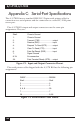
The A/C-7S RO uses a standard, RS-232-C, 25-pin serial printer cable for
connection to a serial printer and for connection to a serial PC/LAN print
server port.
The A/C-7S RO’s input and output connectors use the same pin
assignments. They are:
Shell: Chassis Ground
1: Chassis Ground
2: Transmit (TXD) .........................output
3: Receive (RXD)..........................input
4: Request To Send (RTS) ...........output
5: Clear To Send (CTS) ................input
6: Data Set Ready (DSR) .............input
7: Signal Ground
8-19: No connection
20: Data Terminal Ready (DTR) .....output
Figure C-1. Input and Output Connector Pinout.
The serial printer cable shipped with the A/C-7S RO has the following pin
assignments:
DB25F..............................................DB25M
Shell .................................................Shell
2 .......................................................3
3 .......................................................2
5, 6, 8 ...............................................20
7 .......................................................7
20 .....................................................5,6,8
Figure C-2. Serial Printer Cable Pinout.