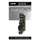
LMC5022C-R3 LMC5023C-R3 LMC5026C-R3 LMC5027C-R3 LMC5110C-R3 LMC5111C-R3 LMC5113C-R3 LMC5114C-R3 LMC5116C-R3 LMC5182C-R3 LMC5117C-R3 LMC5180C-R3 LMC5181C-R3 High-Density Media Converter System II Layer 2 Modules True Layer 2 conversion enables you to extend your network up to 40 kilometers over duplex fiber.
FCC and IC RFI Statements FCC and Industry Canada RF Interference Statements Class B Digital Device. This equipment has been tested and found to comply with the limits for a Class B computing device pursuant to Part 15 of the FCC Rules. These limits are designed to provide reasonable protection against harmful interference in a residential installation. However, there is no guarantee that interference will not occur in a particular installation.
Certifications Certifications Class 1 Laser product, Luokan 1 Laserlaite, Laser Klasse 1, Appareil A’Laser de Classe European Directive 2002/96/EC (WEEE) requires that any equipment that bears this symbol on product or packaging must not be disposed of with unsorted municipal waste. This symbol indicates that the equipment should be disposed of separately from regular household waste.
Table of Contents Table of Contents Part Numbers .................................................................................................. 5 1. Specifications............................................................................................ 6 2. Overview: About the High-Density Media Converter System II Layer 2 Modules ........................................................................................................... 7 3. Configuration..............................................
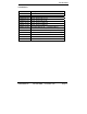
Part Numbers Part Numbers Part Number LMC5022C-R3 LMC5023C-R3 LMC5026C-R3 LMC5027C-R3 LMC5110C-R3 LMC5111C-R3 LMC5113C-R3 LMC5114C-R3 LMC5116C-R3 LMC5117C-R3 LMC5180C-R3 LMC5181C-R3 LMC5182C-R3 LMC5022C-R3 Description TX/FX-MM1300-ST TX/FX-MM1300-SC TX/FX-SM1310/PLUS-ST TX/FX-SM1310/PLUS-SC TX/FX-SM1310/LONG-SC TX/FX-SM1310/LONG-ST TX/SSFX-SM1310-SC (1310xmt/1550rcv) TX/SSFX-SM1550-SC (1550xmt/1310rcv) TX/SSFX-SM1310/PLUS-SC (1310xmt/1550rcv) TX/SSFX-SM1550/PLUS-SC (1550xmt/1310rcv) TX/FX-SM1550/LONG-SC T
Chapter 1: Specifications 1. Specifications DC Input Operating Temperature: Storage Temperature: Humidity: Fiber Optic Specifications Page 6 L2 w/LFPT: 0.80 Amp @ 5V +32° F to +122° F (0° C to +50° C) 0° F to +122° F (-20° C to +70° C) 5 - 95% (non-condensing) For fiber optic specifications, please visit: http://www.blackbox.com 724-746-5500 | blackbox.
Chapter 2: Overview 2. Overview: About the High-Density Media Converter System II Layer 2 Modules The L2 is a Fast Ethernet module which provides a single conversion between 100BASE-TX twisted pair and 100BASE-FX/SX single-mode or multi-mode fiber.
Chapter 3: Configuration 3. Configuration The L2 has user-configurable features (e.g., FiberAlert (FA), TX LinkLoss (TXLL), FX LinkLoss (FXLL), Link Fault Pass-Through (LFPT) and Far End Fault (FEF)). Refer to the Managed Media Converter Module DIP Switch Configuration Table for information on available features. Instructions for installing and configuring both managed (via an SNMP-compatible management application like iView²) and unmanaged modules follow. Page 8 724-746-5500 | blackbox.
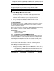
Chapter 4: Install the High-Density Media Converter System II Layer 2 Modules 4. Install the High-Density Media Converter System II Layer 2 Modules The Managed Media Converter Modules install in Black Box SNMP manageable High-Density Media Converter System II chassis. NOTE All modules are hot-swappable. To install a Managed Media Converter Module: 1. Remove the blank bracket covering the slot where the module is to be installed by removing the screws on the outside edges of the bracket. 2.
Chapter 4: Install the High-Density Media Converter System II Layer 2 Modules SNMP Management Module, the High Density L2 Module with Configuration Control will function based on its DIP Switch settings. If the DIP Switches have not been changed, the stored configuration will be used. The stored configuration can be extracted from the SNMP Management Module or the DIP Switches.
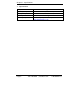
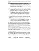
Chapter 4: Install the High-Density Media Converter System II Layer 2 Modules DIP Switch on S1 Feature Default Setting 1 2 3 4 5 6 7 8 Auto Negotiation (AN) Far End Fault (FEF) FX LinkLoss (FXLL) TX LinkLoss (TXLL) FiberAlert (FA) Factory Default Factory Default Factory Default ON OFF OFF OFF OFF OFF OFF OFF 4.
Chapter 4: Install the High-Density Media Converter System II Layer 2 Modules pulses, it knows that the device to which it is connected is up and sending pulses, and that the copper or fiber cable coming from that device is intact. The appropriate “LNK” (link) LED is lit to indicate this.
Chapter 4: Install the High-Density Media Converter System II Layer 2 Modules Regardless if there is a break in segment 1, 2 or 3, the link will drop on the switches at both ends. The link fault is passed through the media conversion and is observed at each end. It acts just like it would if the devices were directly connected. For more information on LinkLoss/FiberAlert, visit the Black Box Web site at http://www.blackbox.com.
Chapter 4: Install the High-Density Media Converter System II Layer 2 Modules WARNING Enable FiberAlert at the remote side of a media conversion only. Enabling it on both sides would keep both transmitters disabled indefinitely. By default FA is disabled. When enabled if, a fault occurs on the fiber line, affecting data in one direction, FA stops sending signal in the opposite direction. FXLL will act on this lack of signal, propagating the loss of like to the copper port when FXLL is enabled.
Chapter 4: Install the High-Density Media Converter System II Layer 2 Modules 4.4 Auto Negotiation on High-Density Media Converter System II Layer 2 Modules L2 modules include the feature Auto Negotiation. When Auto Negotiation is enabled, the module negotiates as a 100 Mbps full-duplex device. If the connected device can operate at 100 Mbps full-duplex, a link is established. Auto Negotiation (DIP Switch #1) is enabled by default.
Chapter 5: Operation 5. Operation 5.1 LED Operation Each L2 module features diagnostic LEDs that provide information on features and ports.
Chapter 6: Troubleshooting 6. Troubleshooting • During installation, first test the fiber and twisted pair connections with all troubleshooting features disabled, then enable these features, if desired, just before final installation. This will reduce the features’ interference with testing. • When working with units where the features cannot be disabled, establish both the twisted pair and fiber connections before the link LEDs will light.
Chapter 7: Contacting Black Box 7. Contacting Black Box Black Box Customer Service Order toll-free in the U.S.: Call 877-877-BBOX (outside U.S. call 724-746-5500) Free technical support, 24 hours a day, 7 days a week. Call: 724-746-5500 or Fax: 724-746-0746 Mail order: Black Box Corporation 1000 Park Drive, Lawrence, PA 15055-1018 Web site: www.blackbox.com E-mail: info@blackbox.com WARNING Disconnect all power supplies before servicing. Page 18 724-746-5500 | blackbox.
Chapter 8: Fiber Optic Cleaning & ESD Precautions 8. Fiber Optic Cleaning Guidelines Fiber Optic transmitters and receivers are extremely susceptible to contamination by particles of dirt or dust, which can obstruct the optic path and cause performance degradation. Good system performance requires clean optics and connector ferrules. 1.
LMC5022C-R3, Rev.