RM610A-R2 Server Side-Mount Wall Cabinet User’s Manual Save space when mounting servers in long BLACK BOX or narrow rooms. ® RM610A-R2 Customer Support Information Order toll-free in the U.S.: Call 877-877-BBOX (outside U.S. call 724-746-5500) FREE technical support 24 hours a day, 7 days a week: Call 724-746-5500 or fax 724-746-0746 Mailing address: Black Box Corporation, 1000 Park Drive, Lawrence, PA 15055-1018 Web site: www.blackbox.com • E-mail: info@blackbox.
Trademarks Used in this Manual Trademarks Used in this Manual Black Box and the Double Diamond logo are registered trademarks of BB Technologies, Inc. Any other trademarks mentioned in this manual are acknowledged to be the property of the trademark owners. We‘re here to help! If you have any questions about your application or our products, contact Black Box Tech Support at 724-746-5500 or go to blackbox.com and click on “Talk to Black Box.
Table of Contents Preface.................................................................................................................................................................................................... 4 Safety .................................................................................................................................................................................... 4 Safety Symbols Used in this Manual.............................................................
Preface/Safety Information Preface This manual is provided to prevent service personnel from committing an act that results in the risk of fire, electric shock, or injury to persons. Only trained service personnel should receive, unpack, and assemble the Server Side-Mount Wall Cabinet. In addition, only trained service personnel should install equipment in enclosures.
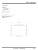
Chapter 1: Specifications 1. Specifications Construction — Body: 14-gauge steel; Doors: 16-gauge steel; Rails: 12-gauge steel Door Height — 24" (60.1 cm) Door Width — 18.5" (46.7 cm) Finish — Black powder coat Maximum Rail Depth — 29.75" (75.6 cm) Mounting Holes — Designed for 1⁄4" hardware Number of Rack Units (RUs) — 10 Rail Type — M5 Size — 24"H x 36.1"W x 20.5"D (60.1 x 91.7 x 52.1 cm) Weight Capacity — 250 lb. (113.6 kg) 36.1" (96.1 cm) Figure 1-1. Front view. EC24U3032 724-746-5500 | blackbox.
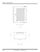
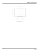
Chapter 1: Specifications Figure 1-2. Right side view. 20.5" (52.1 cm) 19.5" (49.5 cm) 34" (86.4 cm) 36.1" (91.6 cm) Figure 1-3. Top view. Page 6 724-746-5500 | blackbox.
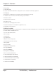
Chapter 1: Specifications 14" (35.6 cm) 16.0" (40.6 cm) 16.0" (40.6 cm) 16.0" (40.6 cm) Figure 1-4. Back view.
Chapter 2: Overview 2. Overview 2.1 Introduction The Server Side-Mount Wall Cabinet is designed for servers and other networking equipment. 2.2 Features • Ships with one conduit panel on the bottom and one gland plate on the top. • 3 RU cabinet accessories also fit the RU openings, top and bottom. • Welded steel frame. • Includes two pairs of M5 rails. • Front door is mesh. • Rear door has mounting positions for fans. • Side panel and doors are removable for equipment access.
Chapter 3: Mounting Instructions 3. Mounting Instructions 3.1 Receiving, Unpacking, and Removing the Server Side-Mount Cabinet from the Box Inspect for damage and report damage if there is damage before receiving. Refer to Section 2.3 for what‘s included in the package. Unpack the enclosure by carefully removing the corrugated carton and corners. Avoid damaging the enclosure when removing packaging. WARNING: Only trained service personnel should remove the enclosure from the pallet.
Chapter 3: Mounting Instructions For a masonry wall surface, the installer must provide the appropriate hardware. 3.4 Loading Equipment WARNING: Only install equipment after the Server Side-Mount Wall Cabinet has been properly secured and mounted to the wall. Maximum Load Capacity = 250 lb. (113.6 kg) 3.5 Power When using power distribution units (PDUs), each PDU should be connected to a committed branch circuit that is rated for the continuous load of all the equipment connected.
Chapter 4: Operation 4. Operation 4.1 Operating the Door The Server Side-Mount Wall Cabinet Enclosure is supplied with two locks (one for the front door and one to lock the middle section to the rear section). The middle section and rear section incorporate a grabber catch that enables the middle section to be held shut without locking. 4.2 Removing or Installing a Door Open the door beyond 90°, remove the top half of the upper hinge, then grasp the door with both hands and carefully lift it upward.
Chapter 5: Optional Accessories Drawings 5. Optional Accessories Drawings Figures 5-1 and 5-2 illustrate two of the Server Side-Mount Wall Cabinet’s optional accessories. Use the gland plate kit to close around cables to prevent unwanted airflow and keep dust and debris out. Figure 5-1. Optional EC3UGP Gland Plate Kit. Use the waterfall bracket to maintain bend radius when routing cables into the cabinet. Optional ECW3U waterfall bracket Figure 5-2. Optional ECW3U Waterfall Bracket.
NOTES RM610A-R2 Page 13
NOTES Page 14 724-746-5500 | blackbox.
NOTES RM610A-R2 Page 15
Black Box Tech Support: FREE! Live. 24/7. Tech support the way it should be. Great tech support is just 30 seconds away at 724-746-5500 or blackbox.com. About Black Box Black Box Network Services is your source for an extensive range of networking and infrastructure products. You’ll find everything from cabinets and racks and power and surge protection products to media converters and Ethernet switches all supported by free, live 24/7 Tech support available in 30 seconds or less. © Copyright 2012.