AUGUST 2000 MD1640A MD1641A Series II Modem 336 Series II Modem 336+ CUSTOMER SUPPORT INFORMATION Order toll-free in the U.S.: Call 7877-877-BBOX (outside the U.S. call 724-746-5500) FREE technical support 24 hours a day, 7 days a week: Call 724-746-5500 or fax 724-746-0746 Mailing address: Black Box Corporation, 1000 Park Drive, Lawrence, PA 15055-1018 Web site: www.blackbox.com • Email: info@blackbox.
Series II Modems 336 and 336+ Series II Intelligent Data/Fax Modems Model 336 (Product Code MD1641A) Model 336+ (Product Code MD1640A) User Guide
SERIES II INTELLIGENT DATA/FAX MODEMS DISCLAIMER This publication may not be reproduced, in whole or in part, without prior expressed written permission from the manufacturer. The manufacturer makes no representations or warranties with respect to the contents hereof and specifically disclaims any implied warranties of merchantability or fitness for any particular purpose.
Table of Contents Contents Chapter 1 - Introduction and Description 1.1 1.2 1.3 1.4 1.5 1.6 1.7 1.8 1.9 Introduction............................................................................7 How To Use This Manual ......................................................7 What is in Your Modem Package? ......................................10 Modem Features ..................................................................10 Fax Features ....................................................................
SERIES II INTELLIGENT DATA/FAX MODEMS 3.7 When to Disable Data Compression ..................................33 3.7.1 Disabling Error Correction ..........................................34 Chapter 4 - Manual Dial and Automatic Answer 4.1 4.2 4.3 4.4 4.5 4.6 4.7 4.8 4.9 4.10 4.11 Introduction ........................................................................35 Dialing/On-Line/Answering ..............................................35 Auto. Leased Line Restoral Operation (336+ Only) ........
Table of Contents 5.4.12 5.4.13 Immediate Action Commands ....................................85 Line Probe Commands ................................................90 Chapter 6 - S-Registers 6.1 6.2 Introduction..........................................................................92 Reading and Assigning S-Register Values ..........................102 6.2.1 Examples of Assigning Values ......................................102 6.2.2 Examples of Reading Values ........................................
SERIES II INTELLIGENT DATA/FAX MODEMS 8.8 8.9 Digital Loopback Test (Local/Manual) (Sync Mode) ......124 Digital Loopback Test (Remote/Auto.) (Sync Mode) ......125 Chapter 9 - DIP-Switch Settings 9.1 9.2 9.3 9.4 Introduction..........................................................................127 DIP-Switch Option Settings ................................................128 Speaker Volume Control ....................................................136 Recording Option Configurations..................
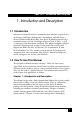
CHAPTER 1: Introduction and Description 1. Introduction and Description 1.1 Introduction Welcome to the world of data communications. You have acquired one of the finest intelligent desktop data/fax modems available today, a Series II Modem from Black Box. Your Series II Modem provides data communication at 33,600-14,400 bps (Enhanced V.34/V.32bis), as well as other prevalent datacomm standards.
SERIES II INTELLIGENT DATA/FAX MODEMS Chapter 2 - Installation and Connection Chapter 2 covers the procedure for connecting the Series II Modem to your computer and to the phone line. Details are given, supported by illustrations on the Modem's back panel connections as a guide to install your Modem to the point of operation. Chapter 3 - Software Configuration Chapter 3 documents communication software configuration recommended specifically for the Series II Modem.
CHAPTER 1: Introduction and Description Chapter 7 - Callback and Remote Configuration Chapter 7 documents instructions on how to operate the Series II Modem's Callback and Remote Configuration features; and the usage of LOGIN Passwords, Set-Up Passwords and Remote Escape Characters as network management tools. Chapter 8 - Testing Your Modem This Chapter covers the modem's built-in test features.
SERIES II INTELLIGENT DATA/FAX MODEMS 1.3 What is in Your Modem Package? Your Series II Modem is made up of many components. Make sure you have them all before trying to operate your modem. Your package should include: • The Series II Modem itself • AC Power Transformer • (2) RJ-11 to RJ-11 telephone cords • This Owner’s Manual • 336+ (MD1640A) only: (1) RJ-11 to spade lugs leased-line cable If any of these items are missing, please contact Black Box. 1.
CHAPTER 1: Introduction and Description Your Series II Modem offers interactive automatic dialing, as well as Command Mode option configuration. You may store up to ten command line/telephone numbers, of up to 60 characters each, in the modem’s nonvolatile memory. The modem pulse or tone dials, and recognizes dial tones and busy signals for reliable call-progress detection. The modem can detect AT&T calling card tones.
SERIES II INTELLIGENT DATA/FAX MODEMS 1.
CHAPTER 1: Introduction and Description Mode of Operation Full duplex over both dial-up lines and 2-wire or (336+ [MD1640A] only) 4-wire leased lines; automatic or manual dialing, automatic or manual answer; and (336+ [MD1640A] only) automatic dial backup on separate lines in leased line operation Intelligent Features Fully “AT command” compatible, microprocessor controlled remote configuration, EIA extended Automode, adaptive line probing, automatic symbol rate and carrier frequency during start-up, ret
SERIES II INTELLIGENT DATA/FAX MODEMS 14 Fax Carrier Frequencies V.21CH2 (Half Duplex) 1650Hz Mark, 1850Hz Space for Transmit Originate 1650Hz Mark, 1850Hz Space for Transmit Answer V.27ter 1800Hz Originate/Answer V.29 QAM 1700Hz Originate/Answer V.17 TCM 1800Hz Originate/Answer Lease Line Restoral 336+ (MD1640A) only: When in dial backup mode, modem attempts leased line restoral periodically (controlled by S-Register S18 setting) Carrier Frequencies 1800 Hz V.32/V.32bis/V.34/Enhanced V.34: 33.6K/31.
CHAPTER 1: Introduction and Description Receiver Sensitivity -43 dBm under worst case conditions AGC Dynamic Range 43 dB Interface EIA RS-232C/ITU V.
SERIES II INTELLIGENT DATA/FAX MODEMS 1.7 Power Power is supplied through an AC power transformer terminated with a standard two-prong plug. The transformer supplies low voltage AC to the modem, and plugs into any conventional 115 volt AC, 60 Hz, twoprong power outlet. The power transformer supplied with the modem is the only one that should be used. Use of any other transformer could cause damage to the modem. A Power On/Off switch is located on the back of the modem. 1.
CHAPTER 1: Introduction and Description 4) 28,800 bps (28.8). This LED behaves differently depending on your connection: • When the modem is connected at 33,600 bps, it blinks 5 times/sec.; • When the modem is connected at 31,200 bps, it blinks once/sec.; • When the modem is connected at 28,800 bps, it is solidly lit. Note: if the modem falls back to 26.4K bps while in V.34 mode, both the 28.8 and 24.0 LEDs light. 5) 24,000 bps (24.0). This LED is lit when the modem is connected at 24,000 bps.
SERIES II INTELLIGENT DATA/FAX MODEMS 13) FAX (FX). This LED is lit when the modem is connected in FAX mode. 14) 336+ (MD1640A) only: ERROR (ERR). When this LED is lit, either the leased line is down and the modem is in dial backup mode, or else the self-test has failed. 1.9 Controls on PC Board The Series II Modem is designed on a single printed circuit (PC) board. This board contains one 16-position DIP-Switch (numbered 1-16). The DIP-Switches are accessible through a cut-out on the side of the modem.
CHAPTER 2: Installation and Connection 2. Installation and Connection 2.1 Safety Warnings 1. Never install telephone wiring during a lightning storm. 2. Never install telephone jacks in wet locations unless the jack is specifically designed for wet locations. 3. Never touch uninsulated telephone wires or terminals unless the telephone line has been disconnected at the network interface. 4. Use caution when installing or modifying telephone lines. 5.
SERIES II INTELLIGENT DATA/FAX MODEMS 2.2 Installation The installation of the Series II Modem consists of making the physical connections necessary to render the modem functional with your computer. This includes making the proper serial, phone line, and power connections. Refer to Figure 2-1 below for the Series II Modem 336 (MD1641A) or to Figure 2-2 on the next page for the Series II Modem 336+ (MD1640A).
CHAPTER 2: Installation and Connection wall jack or the leased-line wall jack or terminal (refer to Figure 2-1 below). For the 336+ (MD1640A) model, run a cord from the PSTN jack to the dialup wall jack if you’re connecting to a dialup line; run a cord from the LEASE jack to the 2- or 4-wire leased-line wall jack or terminal if you’re connecting to a leased line (refer to Figure 2-2 on the next page).
SERIES II INTELLIGENT DATA/FAX MODEMS 2. Attach your Modem to your PC or terminal with an RS-232 (or V.24) cable. 3. Connect telephone set to phone jack (if desired). 4. Attach your Modem to the AC Power transformer and plug t he AC connector into a live AC outlet. 5. Turn on power by flipping the "ON/OFF" switch at the left rear of the Modem to the "ON" position. 6.
CHAPTER 2: Installation and Connection Note: Appendix A lists some basic and specific troubleshooting actions to take if your Modem is not operational. 2.3 Is Your Series II Modem Ready for Use? As soon as you connected power to the modem, it performed a diagnostic self-test. The speed indicators flashed in sequence for approximately four seconds, then the 28.8 indicator is lit. The TR indicator should be lit as well. The SD, RD, CD, and OH indicators should remain off at this time.
SERIES II INTELLIGENT DATA/FAX MODEMS 2.4 Operating Your Series II Modem You control your Series II Modem by issuing AT commands, setting S-Registers, and setting DIP-Switches. You can easily change the settings of your DIP-Switches, as they are located on the right side of your Modem’s chassis.
CHAPTER 2: Installation and Connection 2.4.1 Simple Operations You can dial a number by using the ATD command and the phone number of the modem with which you wish to connect, e.g., ATD6127853500. Your modem will dial the number, and hear a “scrambling” noise as the modem negotiates the kind of connection it can make, and once the modems have settled on a common connection, you will receive a connect message on your computer’s video display.
SERIES II INTELLIGENT DATA/FAX MODEMS 3. Software Configuration 3.1 Introduction Since your communications software configuration is affected by the capabilities of your computer, this chapter begins with a discussion of the limitations of some serial ports and how to identify them. It then discusses communications configuration in general and recommends settings specifically for the Series II Modem. 3.
CHAPTER 3: Software Configuration Macintosh® computers do not use UARTs. The Macintosh SE through IIfx models use a Zilog® Z8530 chip called a Serial Communications Controller, or SCC, that has a maximum speed of 57,600 bps. This speed can be compromised by other serial communications, including printer transmissions and Appletalk®, the networking software that allows Macintoshes to share files. When Appletalk is active it controls all serial communications on the Macintosh.
SERIES II INTELLIGENT DATA/FAX MODEMS 3.2.2 The 16550 UART and Windows 3.1 Windows 3.1 may cause a loss of data when communicating at high speed, even with a 16550 UART installed. Because Windows is multitasking—it switches between several programs running at the same time— it can make the serial port wait briefly while Windows performs other tasks. Meanwhile, incoming data can be lost.
CHAPTER 3: Software Configuration 3.3 Configuring Your Software Communications software must be configured to work with your modem, your computer, and the remote system it is calling. Fortunately, most communications programs make the process easy by providing a default initialization string for your modem as well as defaults for most of the other required parameters. 3.3.
SERIES II INTELLIGENT DATA/FAX MODEMS 3.4 PC Initialization Strings We recommend the following initialization string for a Series II Modem connected to a PC-compatible computer when sharing a line with a telephone: AT &F X4 S0=0 ^M This string resets the Modem to the factory default settings, selects extended result codes with NO DIAL TONE and BUSY, and turns off autoanswer. ^M must end every string sent to the modem from software.
CHAPTER 3: Software Configuration This string selects the factory default parameters, then turns autoanswer off and stores that setting, along with all other current parameters, in nonvolatile memory. The &F9 command causes the modem to load the values from nonvolatile memory the next time it receives the &F command.
Chapter 3: Software Configuration SERIES II INTELLIGENT DATA/FAX MODEMS You can store the initialization string in nonvolatile memory. With your communications software open and connected to the modem’s COM port, type the initialization string in the terminal window, substituting a carriage return for ^M. To store the string, enter AT &F9 &W0 Now you can initialize your modem with the following simple string: AT Z ^M 3.
User Guide for Series II Modems CHAPTER1: Specifications 3.6.2 Terminal Emulation If you are accessing the remote computer as if from an on-site terminal, the keyboard codes used by your computer may not match the ones used by the remote computer. To be compatible with the remote computer, your software must be able to substitute the appropriate codes in what is known as terminal emulation.
SERIES II INTELLIGENT DATA/FAX MODEMS The command to disable compression is AT &E14 . If you have an older UART or if you use your modem mostly for downloading long, compressed files from BBSs, you may want to include the &E14 command in your initialization string as follows: AT &F S0=0 X4 &E14 ^M As a general rule, you should try to transmit files in already-compressed form rather than relying on V.42bis hardware compression.
CHAPTER 4: Manual Dial and Automatic Answer 4. Manual Dial and Automatic Answer 4.1 Introduction We’ll assume that yours is the very common application, where you are using a Series II Modem to dial up a remote computer. The Series II Modem has been factory preset for originating a call to a compatible 33,600 bps modem (also set up for hardware flow control, V.42 error correction, V.42bis data compression and CTS/RTS operation).
SERIES II INTELLIGENT DATA/FAX MODEMS Entering AT automatically sets the modem’s speed to match the speed of the computer or terminal, and also sets the modem’s parity. The AT characters alert the modem that a command follows. The AT Command can also be used to clear the command buffer, by simply typing AT and hitting RETURN. The letter D in a command causes the modem to dial the numbers immediately following it (e.g., ATD7247465500). You have a choice of either pulse (ATDP) or tone (ATDT) dialing methods.
CHAPTER 4: Manual Dial and Automatic Answer 4.3 Automatic Leased Line Restoral Operation (336+ Only) When the Series II Modem 336+ (MD1640A) is in Dial Backup mode, it periodically checks the leased line to see if it's operational and tries to restore the leased line if possible. S-Register S18 determines how often restoral attempts occur. The default for S18 is 30 minutes, and can be set in one minute increments from 10 to 255 minutes.
SERIES II INTELLIGENT DATA/FAX MODEMS After a preset period of time (determined by S-Register S18), the modem automatically tries to restore the leased line. The parameters used to determine if a leased line is down (so automatic dial back can occur), is based on the Series II Modem doing a “retrain” on the leased line due to an error condition in the transmission. An error condition is defined as a "hit" on the line (the Carrier gets interrupted).
CHAPTER 4: Manual Dial and Automatic Answer 4.6 Dial-Up Operation (336+ Only) When your Series II Modem 336+ (MD1640A) is used as a dial-up modem (DIP-Switch #10 in the UP position), it can both originate and answer calls. To originate calls, you use the automatic dialing capability of the Modem's Command mode. To do this, use the computer or terminal keyboard to enter a few command letters, followed by the phone number you wish to dial.
SERIES II INTELLIGENT DATA/FAX MODEMS Once you press the switch, the tone you hear should change to another pitch, or change into a rough-sounding scrambled noise. You then replace the telephone handset in its cradle, and your data communications begins. Note that the Series II Modem may call manually via the keyboard command ATD, or by pressing the Voice/Data switch on the modem's front panel downward.
CHAPTER 4: Manual Dial and Automatic Answer 4.9 Manual Answering We have shown that the Series II Modem can automatically answer incoming calls. The Modem can also answer manually, under your control. The most typical application involves you and another person, who, after carrying on a voice conversation, want to convert to data communications between your modems without having to hang up and dial again. The problem here is that both modems are in originate mode.
SERIES II INTELLIGENT DATA/FAX MODEMS When a call is dialed from the originating modem, the called modem responds to the ringing by switching into Answer mode and by turning on its RI (Ring Indicator, RS-232C/V.24 Pin 22) signal as the rings are detected. (The Modem-MAC does not use DTR.) Note that in order for the called modem to be able to answer the call, it must have a high DTR (Data Terminal Ready) signal. This signal comes from the computer or terminal to which it is attached, on RS232C Pin 20.
CHAPTER 4: Manual Dial and Automatic Answer 4) Abort Timer. Answer Mode: When OH (Off Hook) comes on, the called modem starts a forty-five-second timer and waits for a carrier signal from the originating modem. If carrier is not detected within this period, the modem disconnects (hangs up) and is ready for another call. Originate Mode: The abort timer functions the same as in answer mode, except that the timer begins after the modem has completed dialing, instead of when it first goes off hook.
SERIES II INTELLIGENT DATA/FAX MODEMS 5. Command Mode 5.1 Introduction AT commands are the means by which you, and your communications software, are able to communicate with and configure your modem. They enable you to establish, read, and modify parameters in addition to dialing. The following provides both a summary and a detailed explanation of the AT commands recognized by the Series II Modem. 5.1.
CHAPTER 5: Command Mode 5.1.2 Functional Modes The Series II Modem can be in one of two functional states (see Figure 5-1). These are "Command mode" and "On-line mode". (There is also an inbetween state, "Wait-for-Carrier", where the modem is out of Command mode but not yet really On-Line. When the modem is initially powered up, it is in Command mode and is ready to accept commands from your keyboard or software.
SERIES II INTELLIGENT DATA/FAX MODEMS COMMAND MODE +++AT Dial (D or A) command, or incoming phone call HANG UP WAIT FOR CARRIER no carrier detected carrier detected ON-LINE MODE carrier lost AT0 command Figure 5-1. Functional Modes 5.2 Summary of AT Commands A wide variety of autodial operations and modem options can be controlled when the Series II Modem is in Command Mode. Remember, nearly all commands begin with AT. These commands are organized into several functional groups.
CHAPTER 5: Command Mode ; R ! $ @ MEMORIZE PHONE NUMBERS D...
SERIES II INTELLIGENT DATA/FAX MODEMS CONTROL RS232C INTERFACE &C &D &R &S &RF &SF Carrier Detect Control Data Terminal Ready Control Clear To Send Control Data Set Ready Control CTS/RTS Control DSR/CD Control CONFIGURE ERROR CORRECTION &E0 &E1 &E2 #L0 Normal Mode Auto-Reliable Mode Reliable Mode Negotiate V.
CHAPTER 5: Command Mode $EB CONFIGURE DATA COMPRESSION #P 336 (MD1641A) only: 10/11-Bit Asynchronous Format Parity Selection &E14 &E15 Data Compression Disabled Data Compression Enabled CONFIGURE SPEED $BA0 CONVERSION $BA1 $MB $SB EXECUTE IMMEDIATE ACTION COMMANDS $H I I9 L5 L6 L7 EXECUTE LINE PROBE COMMANDS %DF Speed Conversion On Speed Conversion Off Set modem speed (e.g., $MB33600) Set serial port speed (e.g.
SERIES II INTELLIGENT DATA/FAX MODEMS READ AND ASSIGN S-REGISTER VALUES Sr? Sr= REMOTE CONFIGURATION & CALLBACK SECURITY #CBN Passwords for Callback Phone #s #DB Callback Security Enable/Disable #I Change LOGIN Password #RCBNxx Erase Password Linked with Memory Location xx #S Change SETUP Password TEST MODEM U &T Read Current S-Register Value Assign S-Register Value Self-Test Modem (Chapter 8) Enable/Disable Digital Loopback Signal 5.
CHAPTER 5: Command Mode The following tables define the result codes generated by the &Q command (refer to Appendix G for Result Code Summary).
SERIES II INTELLIGENT DATA/FAX MODEMS 5.4 Dialing Commands 5.4.1 Dialing Action Commands Dial Command D The letter D in a command causes the Series II Modem to dial the telephone number immediately following it. For example, if you enter ATD5551212 and hit RETURN, the Modem dials the number 555-1212. The D command is also used in conjunction with a telephone set for manual dialing.
CHAPTER 5: Command Mode This command would be used only if you had already reached a busy number after executing a normal dial command. You simply enter A: (you need not enter AT, nor do you need to hit RETURN), and the modem will redial the number for you. If you again reach a busy signal, it re-dials again and again until it no longer detects a busy signal. You can stop the Series II Modem from re-dialing by pressing any key.
SERIES II INTELLIGENT DATA/FAX MODEMS Voice/Data Dialing $VD Another alternate method of causing the Series II Modem to automatically dial is Voice/Data Dialing. With Voice/Data Dialing, the modem automatically dials the phone number stored in the N1 position of memory whenever the Voice/Data switch is toggled. You must first enter AT$VD1&W0. This command string enables Voice/Data dialing when the Voice/Data toggle switch is activated.
CHAPTER 5: Command Mode Nearly all telephone systems in the U.S. are now compatible with tone dialing. Since that is the faster method, you will probably choose the tone method for your dialing. An example of combining pulse and tone dialing could involve a PBX system where 9 had to be pulse-dialed first, then the rest of the number tone-dialed after pausing for a second dial tone. The number would be dialed by entering ATDP9, T5551212 and RETURN. (The comma causes a pause, which we’ll explain soon.
SERIES II INTELLIGENT DATA/FAX MODEMS Wait for New Dial-Tone W A W inserted in the dialing command causes the Series II Modem to wait for another dial tone, and not resume dialing until another dial tone is detected. It is not necessary to enter a W at the beginning of the dialing command to wait for a modem dial tone, because the modem will do that first (pause automatically).
CHAPTER 5: Command Mode Flash On Hook ! Some switchboard systems react to a momentary On Hook. An exclamation mark inserted in the command causes the modem to “flash” on hook for a half of a second, as if you had held the switch hook button on a telephone down for a half second. For example, to flash On Hook after dialing the number 555-1234 in order to transfer to Extension #5678, you might enter ATDT5551234,,!5678. The commas cause a 4 second pause (just to be safe).
SERIES II INTELLIGENT DATA/FAX MODEMS for at least one ringback and 5 seconds of silence. If a busy signal is detected, the Series II Modem hangs up and generates a BUSY result code. If it does not detect 5 seconds of silence, a NO ANSWER result code is generated after hanging up. If 5 seconds of silence is detected, the second number (746-5500) is then dialed. 5.4.3 Phone Number Memory Commands Storing Phone Numbers D...
CHAPTER 5: Command Mode To link the number in N1 to the number N2, simply enter ATN1N2 and hit RETURN. Several numbers can be linked in the same command. For example, you could link N1 to N2 to N3 to N4 by entering ATN1N2N3N4 and RETURN or you could link N1 to N2 and back to N1 and then back to N2 by entering ATN1N2N1N2 and RETURN. The only limit on the number of numbers that can be linked is the 60 characters allowed in a command line.
SERIES II INTELLIGENT DATA/FAX MODEMS 5.4.4 Configuration and Default Storage Commands Store Configuration & S-Register Parameters in Non-Volatile Memory &W The Series II Modem can store configuration parameters and S-Register values in its nonvolatile read/write Random Access Memory (RAM) memory. The &W command does this, which prevents any reconfiguration from being lost on a power-down or Reset (ATZ) condition.
CHAPTER 5: Command Mode Many datacomm program issue the &F command automatically—the &F9 command allows the user to select their own factory defaults. Note that the &F8/&F9 commands should be used with &W0.
User Guide for Series II Modems SERIES II INTELLIGENT DATA/FAX MODEMS The #V command gives the user the option of including V.32terbo as part of the handshaking process in both Orignate and Answer modes. Entering AT#V0&W0 includes the V.32terbo mode in handshaking. Entering AT#V1&W0 disables the Series II Modem 336 from using V.32terbo mode in the handshaking process (default). Async/Sync Mode Switching &M This command can be used to set the on-line mode to either synchronous or asynchronous.
Chap 5: Command Modeter CHAPTER1: Specifications 5.4.5 Command Response (Result Code) Commands Echo Command Mode Characters E If the Series II Modem is connected to a full-duplex computer, it may be necessary for the modem to be configured to echo back characters entered while in the Command Mode in order for them to be displayed. The E command is used to configure the Command Mode echo, with ATE0 disabling the echo and ATE1 enabling the echo (default).
SERIES II INTELLIGENT DATA/FAX MODEMS Result Codes (Verbose/Terse) V The V command controls whether the Series II Modem’s result codes are displayed as word (“verbose”) or single digit (“terse”) messages. For example, if after dialing, no carrier signal is detected, the resulting message can be displayed either as NO CARRIER, or as the digit 3. Entering ATV0 (or ATV) causes the Modem to display the Result Codes as digits, while ATV1 displays them as words.
CHAPTER 5: Command Mode Regarding the Series II Modem’s method of dialing, the Modem can detect standard dial tones and busy signals. This capability (“smart dialing”) allows the modem to wait for a dial tone, and when one is detected, to begin dialing immediately. The Modem also can detect a distant busy signal if, after dialing, it reaches a busy number. This is useful because it allows the modem to immediately abandon a call, rather than wait 45 seconds for a carrier signal that will never come.
SERIES II INTELLIGENT DATA/FAX MODEMS 5.4.6 Phone Line Conditioning Commands Guard Tones &G The &G command is used to control the presence or absence of guard tones from the transmitter when in Answer mode, at either 1200 or 2400 bps. Guard tones are used in Europe and other areas for the modem to function in the telephone systems. Guard tones are not used in the United States. &G0 (default), turns off CCITT guard tones. &G1 turns on 550 Hz guard tones. &G2 turns on 1800 Hz guard tones.
CHAPTER 5: Command Mode codings except under an unusual line condition called impulse noise. AT#T0 turns Trellis coding off and AT#T1 turns Trellis coding on (factory default). Fallback Modes When On-Line #F If line conditions deteriorate, the Series II Modem automatically drops its transmission speed (“fallback”). The #F command controls the different ways the Modem falls back. During operation, if the error rate becomes too great, the modem performs a retrain.
SERIES II INTELLIGENT DATA/FAX MODEMS Auto Speed Detect #A The function of the #A command is to detect and select the operational data rates (the “starting” speeds) with which the Series II Modem uses for initial handshake and speed selection. Remember, this command does not control the originating data rate of the modem (that is done by the Modem Baud Rate command $MBn), but only the Answer mode “starting” speeds.
CHAPTER 5: Command Mode Data Terminal Ready Control &D Data Terminal Ready (DTR) on Pin 20 of the RS232C interface is required in order for the Series II Modem to operate. A high DTR signal tells the modem that the device to which it is connected is active, or "ready" to communicate through the modem. If the signal is not being provided on the RS232C interface, you can force DTR high with DIP-Switch #1 (Chapter 9). DTR has some other Modem functions.
SERIES II INTELLIGENT DATA/FAX MODEMS Data Set Ready Control &S The &S command allows you to control the status of the Data Set Ready signal (DSR, Pin 6) on the RS232C interface. You have three choices. You can force the signal high, allow it to act normally, or set it to stay high until the modem disconnects, go low momentarily, and then go high again. The last option is useful with some CBX phone systems and mainframe front ends, which require DSR to act in this manner.
CHAPTER 5: Command Mode Normal Mode &E0 In Normal mode of operation, the Series II Modem’s V.42 error correction capabilities are disabled, and the modem functions as a non-errorcorrecting modem. Auto-Reliable Mode &E1 In Auto-Reliable mode during the handshaking procedures at the start of the on-line connection, the Series II Modem automatically determines whether or not the modem with which it is communicating is using V.42 error correction. If the Modem determines that the other modem is using V.
SERIES II INTELLIGENT DATA/FAX MODEMS Reliable Mode &E2 In Reliable mode, the Series II Modem uses its V.42 error correction capabilities during all transmissions, and must be connected to another modem with a similar protocol activated (MNP or LAP-M). V.42 Mode Select #L The V.42 standard implements both MNP Class 3 & 4 and LAP-M error correction methods. The V.42 Mode Select command (#L) selects which type of error correction (MNP or LAP-M) your Series II Modem uses for transmissions.
CHAPTER 5: Command Mode This command is for Originate mode only. Answer mode still accepts MNP or LAP-M. #L3 Command In the prior commands, the modems use a two phase process to establish a V.42 connection (detection to establish whether the remote modem is also error correcting, and then protocol establishment to determine parameters and to establish the error correction connection). If you know that the other modem is a V.
SERIES II INTELLIGENT DATA/FAX MODEMS The $F command can be used to disable this fallback-to-Normal-due-toCARRIAGE-RETURN feature. The Auto-Reliable fallback character ($F) and Auto Reliable buffering ($A) commands can be used together to cause the modem to buffer all data received up until the CARRIAGE RETURN, and then drop to Normal mode. All data received will then be output following the CONNECT message. AT$F0 = Do not fall back to Normal if CARRIAGE RETURN received.
CHAPTER 5: Command Mode V.42 Error Correction/300bps $E At 300 bps, error correction is not typically used. $E1 lets the Series II Modem function at 300 bps in either Normal (&E0), Auto-Reliable (&E1) or Reliable (&E2) mode. $E0, which is the Modem’s default, disables 300 bps/V.42 error correction altogether. AT$E0 = No V.42 Error correction at 300 bps. AT$E1 = V.42 Error Correction at 300 bps. The factory default setting is $E0. 5.4.
SERIES II INTELLIGENT DATA/FAX MODEMS Modem-Initiated Flow Control RS/232/V.24 Modem data flow Computer or Terminal Computer-Initiated Flow Control Modem RS/232/V.24 data flow Computer, Terminal, or Printer Figure 5-2. Flow Control and Pacing Hardware Flow Control &E4 With Hardware Flow Control, the modem uses its RS232C interface to control the flow of data from the computer or terminal to which it is attached.
CHAPTER 5: Command Mode Xon/Xoff Flow Control &E5 Xon/Xoff is the most commonly used method of flow control. Under this method, control characters known as “Xon” and “Xoff” are inserted by the modem into the data to start and stop the flow of data from the computer or terminal to which the modem is attached. Xoff, which is a Control-S, stops the flow of data, and Xon, which is a Control-Q, restarts it.
SERIES II INTELLIGENT DATA/FAX MODEMS When two Series II Modems are connected in Normal mode (not using error correction), Xon/Xoff can be used to control the flow of data between the modems. Flow Control can be turned on or off with the Normal Mode Modem Flow Control commands. When the modems are connected in Reliable mode, a different method of modem Flow Control is used, and the commands for Normal Mode Modem Flow Control are ignored.
CHAPTER 5: Command Mode connected in Reliable mode, a different method of modem flow control is used, and the commands for Normal Mode Modem Flow Control are ignored. When you are using Speed Conversion in Normal Mode, you must activate the modem’s Normal Mode Modem Flow Control. (Speed Conversion is explained in Section 5.4.11.
SERIES II INTELLIGENT DATA/FAX MODEMS Asynchronous Word Length Selection $EB (336 Only) The Series II Modem 336 (MD1641A) has an 11-bit capacity when operating asynchronously. The $EB command selects between 11-bit and 10-bit operation. AT$EB1 enables 11-bit format (1 start bit, 8 data bits, 1 parity bit, and 1 stop bit). AT$EB0 (default) enables 10-bit format (1 start bit, 7 data bits, 1 parity bit, and 1 stop bit). $EB is functional in both command and on-line mode.
CHAPTER 5: Command Mode 5.4.10 Compression, Error Correction, Flow Control, Pass-Through and Pacing Commands The Series II Modem has a variety of commands to control its error correction and data compression options. These additional commands are listed below. (Remember to precede each command with the AT characters.) Factory-default settings are marked with asterisks.
SERIES II INTELLIGENT DATA/FAX MODEMS Enq/Ack Pacing Commands: &E8 = Enq/Ack method of pacing off* &E9 = Enq/Ack method of pacing on Normal Mode Modem Flow Control Commands: &E10 = Normal Mode Modem Flow Control off* &E11 = Normal Mode Modem Flow Control (Xon/Xoff) on Computer-or Terminal-Initiated Flow Control (Pacing) Commands: &E12 = Pacing off* &E13 = Pacing on (either RTS on/off or Xon/Xoff depending on the setting of &E4 or &E5).
CHAPTER 5: Command Mode computer must be set at a fixed baud rate, regardless of whether the modem is communicating over the phone line at 300, 1200, 2400, 9600, 14,400,19,200, 24,000, 28,800 or 33,600 bps.
SERIES II INTELLIGENT DATA/FAX MODEMS The command to set the Modem Baud Rate is AT$MBn, where n can be 300, 1200, 2400, 4800, 9600, 14,400,19,200, 28,800 or 33,600 bps as listed below: AT$MB300 AT$MB1200 AT$MB2400 AT$MB4800 AT$MB9600 AT$MB14400 AT$MB19200 AT$MB28800 AT$MB33600 = = = = = = = = = 300 bps 1200 bps 2400 bps 4800 bps 9600 bps 14400 bps 19200 bps 28800 bps 33600 bps The factory default is 33600 bps.
CHAPTER 5: Command Mode same. This provides you with a convenient way to switch the serial port speed, and still make it easy to go back to the original speed automatically the next time the modem is powered up or reset with an ATZ command.
SERIES II INTELLIGENT DATA/FAX MODEMS At the time of this writing, we have three screens of Help information (Screen #1, #2 and #3), and more screens may be added in the future.
CHAPTER 5: Command Mode Listing Current Operating Parameters L5 L7 The L5 and L7 commands list the current operating parameters of your modem. This information can be very useful when you are changing communications software or when you are changing modem default settings. The command to list the Series II Modem’s current operating parameters is ATL5 for the basic parameters. Entering ATL7 lists additional parameters on the Modem.
SERIES II INTELLIGENT DATA/FAX MODEMS File Edit Setup Perform Transfer Windows Feb29, 96 4:50pm MEWDEF Help Connected to device 00:04:55 DCD CTS DSR 024 2A71 *********** 0213 ONLINE DIAGNOSTICS *********** LINK TYPE LINE SPEED SERIAL SPEED ERROR CNTRL/COMPRESS FALL BACK/FORWARD DATA FORMAT SYMBOL RATE(SYMETRIC) CARRIER FREQUENCY TRELLIS ENCODER PRECODING LINE TYPE V.34 28800/26400 19200 LAPM LOCALLY ENABLED ASYCHRONOUS 3429/3429 1959/1959 4D 16-STATE/4D 16-STATE OFF/OFF DIAL UP RECV.
CHAPTER 5: Command Mode When this is done, the modem escapes to Command Mode, executes the command (if any), and then remain in Command mode. For example, to hang up the modem at the end of a call, enter +++ATH and hit RETURN. There is no need to incorporate pauses before and after the plus signs, as done in earlier modems. BREAK AT The Series II Modem provides an alternative Escape method, using a Break signal as the Escape Code.
SERIES II INTELLIGENT DATA/FAX MODEMS Force Answer Mode A You can force the Series II Modem into Answer mode with the modem’s A command. Entering ATA when in Command mode immediately brings your modem off-hook, out of Command mode and into On-Line Answer mode, and causes it to transmit its carrier signal over the phone line.
CHAPTER1: Specifications These commands are listed below. Enable/Disable Reading of Line Probe Information Commands: %DP0 Do not read Line Probe information from DSP during handshake (Default). %DP1 Read Line Probe information from DSP during handshake. Format of Line Probe (Graph or Table) Commands: %DF0 Data is displayed in Graph format. Y axis is shown in dBms (Default). %DF1 Data is displayed in Table format. Numeric values are displayed 150 Hz to 3750 Hz in 75-Hz increments.
SERIES II INTELLIGENT DATA/FAX MODEMS 6. S-Registers 6.1 Introduction Certain Command Mode configurations are stored in memory registers called, S-Registers. The S command is used to assign a value to, and to read the current value of an S-Register. To assign a value to an SRegister, enter the letter S, followed by the S-Register number and an equals sign (=), and then a decimal response to the message “ENTER THE NEW VALUE IN DECIMAL FORMAT”.
CHAPTER 6: S-Registers time an incoming ring signal is detected, S1 increases its value by one, up to a maximum of 255. If you set S1 to a value other than its default value of zero, or if the value is increasing with rings, this new value remains stored in S1 for eight seconds after the last ring is counted, after which time the value reverts to zero. S2 Escape Code Character Unit: Range: Default: Description: Decimal equivalents of ASCII characters 0-127 43 (+) S2 defines the escape code character.
SERIES II INTELLIGENT DATA/FAX MODEMS S5 Backspace Character Unit: Range: Default: Description: Decimal equivalents of ASCII characters 0-127 8 (^H) S5 defines the character recognized as BACKSPACE. S5 may be set for any ASCII character. S6 Wait Time for Dial Tone Unit: Range: Default: Description: Seconds 2-255 2 S6 sets the time the modem waits after the RETURN key is pressed before executing a dial command. The default setting is two seconds.
CHAPTER 6: S-Registers default setting is two seconds. S8 may be set for up to 255 seconds. S8 also sets the time the modem waits before retrying a call after detecting a busy signal. Some computer systems need more than two seconds to reset (in which case you should increase the value of S8).
SERIES II INTELLIGENT DATA/FAX MODEMS S11 Tone Dialing: Tone Spacing and Duration Unit: Range: Default: Description: Milliseconds (mSec) 1-255 70 S11 sets the speed of tone dialing (spacing and tone duration times). The default value is 70 mSec, meaning that each tone is on for 70 mSec with a 70 mSec pause between each. The minimum S11 value allowed by most telephone systems is 50 mSec. Very few telephone systems can handle anything faster than that. The maximum S11 value is 255 mSec.
CHAPTER 6: S-Registers S16 Callback Attempts Unit: Range: Default: Description: Attempts 1-255 4 S16 defines the number of attempts allowed after initial passwords have been exchanged between modems. S17 Changing Break Time Unit: Range: Default: Description: 10-mSec intervals 0-250 250 S17 defines the break time (space) sent to the local PC. The default is set for a 250-mSec (2.5-second) break. The break time can be changed in 10-mSec increments by increasing or decreasing the value of S17.
SERIES II INTELLIGENT DATA/FAX MODEMS S19 Dial-Back Timer (336+ Only) Unit: Range: Default: Description: Minutes 0-255 1 In the Series II Modem 336+ (MD1640A), S19 is a timer that begins when the lease line goes down. S19 specifies the duration of time the modem attempts to reestablish the lease line connection.
CHAPTER 6: S-Registers dropout time can be increased in 100-mSec intervals, up to a maximum of 25.5 seconds (S25 set to 255). The default S25 setting of zero corresponds to a dropout time of 50 mSec. All other possible settings (1 through 255) correspond to their multiples of 100 mSec. S26 Failed Password Attempts Unit: Range: Default: Description: Failed attempts 0-255 0 S26 counts the number of times there has been a failed password attempt.
SERIES II INTELLIGENT DATA/FAX MODEMS S30 Inactivity Timer Unit: Range: Default: Description: Minutes 0-255 0 S30 causes the modem to disconnect if no data is transmitted or received for a specified time. This timer runs during both Reliable and Normal error correction connections. The timer restarts any time a data character is passed through the serial port (either sent or received). If noise on the phone line causes an error to be received during Normal mode, this also restarts the timer.
CHAPTER 6: S-Registers S36 Time Between DTR Inactive and Modem Off-Hook Unit: Range: Default: Description: Seconds 0-255 0 The DTR Busy-out feature uses S-Register S36 to set the time between DTR inactive (low) and the modem going off-hook. S36 can be set in onesecond intervals from 0 to 255 seconds. With the default setting of S36=0, DTR Busy-Out is disabled (i.e., DTR won't Busy-Out).
SERIES II INTELLIGENT DATA/FAX MODEMS 6.2 Reading and Assigning S-Register Values The S command is used to assign a value to, and to read the current value of, an S-Register. To read an S-Register value, enter the letter S followed by the S-register number and a question mark (?), then hit RETURN. For example, entering ATS7? and hitting RETURN displays the value of S-Register S7 in a 3-digit decimal form.
CHAPTER 6: S-Registers 6.2.2 Examples of Reading Values To verify that you entered the value correctly in the above examples, enter ATS8? and hit RETURN in the first example, ATS0? in the second, and ATS2? in the third example. You should receive the response 005 in the first example, 030 in the second example, and 055 in the third example. When configuring the S-Registers, it is a good practice to include the verification read-entry in the same command line as the configuration assignment-entry.
SERIES II INTELLIGENT DATA/FAX MODEMS 7. Callback Security and Remote Configuration 7.1 Introduction This chapter describes how the Series II Modem Callback and Remote Configuration features operate. These features use a multilevel security system, which involves the use of LOGIN Passwords, Setup Passwords and Remote Escape Characters. The primary level security code is the modem’s LOGIN Password. Once this password is entered, other passwords can be used.
CHAPTER 7: Callback Security and Remote Configuration long). You use the modem's LOGIN Password and the Set-Up Password plus special Callback commands to access this memory. The memory is thirty numbers long and replaces your modem's normal phone number memory. Each number is 35 characters long and can contain commands as well as phone numbers. You need to set up your modem with the numbers and codes as part of the dial back initialization procedures.
SERIES II INTELLIGENT DATA/FAX MODEMS Table 7-1. Modem LOGIN, Setup and Remote Escape Code Procedures To change your modem’s LOGIN Password and Setup Password: Step Procedure Note: Passwords are upper/lower case sensitive. The case you enter here is the case that must be used at Log-In. 1. Type AT#IBLACK BOX and hit RETURN. Your modem will respond with: OK (if the LOGIN Password is wrong, the modem’s response is ERROR) 2. Type AT#SMODEMSETUP and hit RETURN.
CHAPTER 7: Callback Security and Remote Configuration To turn your modem's Callback Security feature on and off: 7. If you want Callback Security with both remote and local password security, enter AT#DB1 and hit RETURN. You must turn on Callback Security to be able to enter dial back phone numbers. 8. If you want Callback Security on with just remote password security, enter AT#DB2 and hit RETURN. You must turn on Callback Security to be able to enter dial back phone numbers.
SERIES II INTELLIGENT DATA/FAX MODEMS Table 7-2. Callback Password and Dial Back Phone Number Entry Procedures Step 1. Procedure Enter your modem's LOGIN Password (as selected in Table 7-1) by entering the following: AT#Ixxxxxxxxxx (xxxxxxxxxx from Table 7-1) Enter your modem's Setup Password (as selected in Table 7-1) by entering the following: AT#Syyyyyyyyyy(yyyyyyyyyy from Table 7-1) 2.
CHAPTER 7: Callback Security and Remote Configuration AT+ - DT...????N1 (number for location N1)...etc Note: You must indicate within the command string that the modem either Pulse dials (ATDP...) or Tone dials ATDT...). The maximum length of the number is 35 characters. The number may include commands as well as your number, so as to create macro-type command numbers. The + and/or - characters entered before the phone number are optional.
SERIES II INTELLIGENT DATA/FAX MODEMS Table 7-3. Callback Operational Sequence Procedures Perform the following steps when dialing into a dialback modem: Step 1. Procedure When called, the modem answers and after a slight delay, responds with: Password> 2. Enter your modem's LOGIN Password (Table 7-1) and hit RETURN. If entered correctly, the modem responds with: DB> 3.
CHAPTER 7: Callback Security and Remote Configuration 7.3.2 Remote Configuration Procedures The procedures for using the Remote Configuration features are the same whether or not a call originates from the remote modem. Once the modem is on-line, perform the procedures in Table 7-4. Table 7-4 Remote Configuration Operation Procedures Procedure Step 1. Remote Escape Configuration requires %%%AT to be sent if the default value in S-Register S13 has not been changed. The modem responds with: 1.
SERIES II INTELLIGENT DATA/FAX MODEMS 7.4 Remote Configuration and Callback Security AT Commands The following AT commands are used with Remote Configuration and Callback Security features. Assign Passwords for Callback Phone Numbers #CBN When you have callback security enabled for the Series II Modem, anyone trying to connect with the modem will be required to furnish a password. The #CBN command allows you to enter passwords for each of the 30 memory locations used for callback security.
CHAPTER 7: Callback Security and Remote Configuration Change LOGIN Password #I The default LOGIN password for your Series II Modem is "BLACK BOX".
SERIES II INTELLIGENT DATA/FAX MODEMS 7.5 Remote Configuration/Callback Security S-Registers The following S-Registers are used with Remote Configuration and Callback Security features. Remote Configuration Character (S13) S13 defines the Series II Modem remote configuration escape character. When the S13 character is entered three consecutive times from a remotely connected site, your modem responds to it with its Remote Configuration procedure.
CHAPTER 7: Callback Security and Remote Configuration Failed Password Attempts (S26) S26 counts the number of times there has been a failed password attempt. For example, if you entered ATS26? and the message 003 were displayed, that would mean someone had failed three times to gain access to your modem using its password security system.
SERIES II INTELLIGENT DATA/FAX MODEMS 8. Modem Testing 8.1 Introduction Each time you power up the Series II Modem, it performs an automatic self- test to ensure proper operation. The Modem also has four diagnostic test features: Local Analog Loopback, Digital Loopback (remote/automatic), Digital Loopback (local/manual) and a modem Back-to-Back test. A loopback test involves entering data from your PC and looping that data through the circuits of your modem and/or a remote modem.
CHAPTER 8: Modem Testing 8.2 Local Analog Loopback Test/V.54 Loop 3 In this test, data from your computer or terminal is sent to your modem's transmitter, converted into analog form, looped back to the receiver, converted into digital form and then received back at your monitor for verification. No connection to the phone line is required. See Figure 8-1. Computer or Terminal UUUUU UUUUU Local Series II Modem digital analog Type ATU0 or ATU1; hit ENTER Figure 8-1.
SERIES II INTELLIGENT DATA/FAX MODEMS 5. When testing is completed, you may exit Answer mode by entering an Escape Sequence (+++AT or AT), which returns the modem to Command mode. 6. Your modem passes this test if the data entered from your keyboard is the same as the data received on your monitor. If different data is appearing on your monitor, your modem is probably causing the problem, although it could also be your computer.
CHAPTER 8: Modem Testing In this test the local modem is placed in Digital Loopback mode. Data is entered and transmitted from the remote modem (which is not in digital loopback mode), sent across the phone line to the local modem and looped back to the remote modem. The test procedure is as follows: 1. Go into Terminal mode. Type AT and hit ENTER; you should get an OK message. 2. Dial the remote modem by entering the Dial command and the phone number, to establish On-line mode. 3.
SERIES II INTELLIGENT DATA/FAX MODEMS 8.4 Digital Loopback Test/V.54 Loop 2 (Remote/Automatic) In this test, your modem must be On-line with another modem set up to respond to a request for Digital Loopback, such as another Series II Modem. With the Modem, this ability to respond is controlled by the &T command. AT&T4 enables the response to Digital Loopback Test (remote/automatic). AT&T5 disables the response.
CHAPTER 8: Modem Testing 3. Type the Escape Sequence (+++AT or AT) which brings your modem into Command mode, while still maintaining the connection with the remote modem. 4. Type ATU2 and hit ENTER. The local modem responds to this command by transmitting an unscrambled marking signal, which causes the remote modem to place itself in Digital Loopback mode. Then the local modem exits Command mode and enters pseudo On-line mode. 5. Type data from your keyboard.
SERIES II INTELLIGENT DATA/FAX MODEMS 6. Set DIP-Switch # 3 UP on both local and remote modems. This changes the transmit level to -15dB and this change is necessary to operate in back-to-back mode 7. Turn on both units and wait for carrier detect (CD). 8. Short out pins 2 and 3 on the RS-232C interface on the remote modem (with a paper clip or some other metal device, for example).
CHAPTER 8: Modem Testing 9. Entered characters should echo back to the sending modem. DTE “Local” Back-to- “Remote” modem back cable modem Figure 8-4B. Back-to-Back Testing 8.6 Synchronous Mode Testing The following tests must be run with your modem in Synchronous mode (DIP Switch #12 in the Up (OPEN) position), DIP Switch #9 controls the modem’s Synchronous mode testing function. (Refer to Chapter 9 for DIP Switch information.
SERIES II INTELLIGENT DATA/FAX MODEMS To initiate the Local Analog Loopback Test, with the modem in Synchronous mode: 1. Enter AT&M1U. This first switches your modem form asynchronous to synchronous mode, and places it into the Analog Loopback/Originate mode. The modem is now out of the Command mode and in the pseudo On-Line mode. 2. Once you receive a connect message (if responses are enabled), enter data from your keyboard.
CHAPTER 8: Modem Testing data passed from the remote modem’s transmit circuit are looped back from the local modem and are received at the remote modem’s receive circuit (multiple upper case “U” characters in Figure 8-6). First make certain that you are set up for Synchronous operation by placing DIP-Switch #12 in the UP position.
SERIES II INTELLIGENT DATA/FAX MODEMS in Figure 8-6), the Local Analog Loopback Test should be performed on both the remote and local modems. If that test is successful, the problem may be the phone lines. First make certain that you are set up for Synchronous operation by placing DIP-Switch #12 in the UP position. To initiate the Digital Loopback Test (remote/automatic), DIP-Switch #9 must be in the DOWN position, and the Answer/Originate switch (front of the modem) must be toggled to the UP position.
CHAPTER 9: DIP-Switch Settings 9. DIP-Switch Settings 9.1 Introduction There are several DIP-Switch options on the Series II Modem’s printed circuit (PC) board. The DIP-Switches are accessible through a cut-out on the side of the modem. This chapter explains the Modem printedcircuit board options. Sixteen DIP-Switch settings and the modem's speaker volume control are explained in detail, including all default settings. FRONT Power switch Speaker Power jack RS/232/V.
SERIES II INTELLIGENT DATA/FAX MODEMS FRONT Power switch Speaker Power jack RS/232/V.24 connector LEDs Volume knob Leased-ine jack 16-position DIP switch Voice/Data switch with Answ/Orig OPEN OPEN 1 2 3 4 5 6 7 8 9 10 11 12 13 14 15 16 Dialup jack Phone jack REAR Figure 9-2. Series II Modem 336+ (MD1640A) PC Board 9.2 DIP-Switch Option Settings Switch #1 Forced DTR -- "DTR" (Asynchronous/Synchronous Mode/Leased Line/Dial-Up) The Series II Modem must have a high DTR signal in order to operate.
CHAPTER 9: DIP-Switch Settings Switch #2 Flow Control - &E4/&E5 (Asynchronous Mode/Leased Line/Dial-Up) With Hardware Flow Control, the modem uses its RS-232C/V.24 interface to control the flow of data from the computer or terminal to which it is attached. The CTS signal on Pin 5 of the RS-232C/V.24 is brought low to stop the flow of data, and is brought high to restart it. Place DIP-Switch #2 in the UP position to enable Hardware Flow Control (&E4).
SERIES II INTELLIGENT DATA/FAX MODEMS Switch #3 Enable/Suppress Responses -- "Q" (Asynchronous Mode/Dial-Up) In some Asynchronous mode applications, you may want to suppress all responses from the modem. Place DIP-Switch #3 in the DOWN position to enable Result Code responses (Q0). Place DIP-Switch #3 in the UP position, and answer mode is handled without responses and echo turned off (Q2), but originate is still intelligent.
CHAPTER 9: DIP-Switch Settings AS/400 Mode Enabled AS/400 Mode Disabled Factory Default Setting = Switch #4 DOWN = Switch #4 UP = UP Switch #4 Unix UUCP Spoofing (Asynchronous Mode/Leased Line/Dial-Up) The Series II Modem can be configured for use with Unix equipment which employs ACK flow control to monitor data integrity. The Modem can do "UUCP spoofing", where the modem is able to generate ACKs at the DTE interface.
SERIES II INTELLIGENT DATA/FAX MODEMS Originate Mode Enabled = Switch #5 DOWN Answer Mode Enabled = Switch #5 UP Factory Default Setting = UP) Switch #6 Maximum Throughput Setting (Asynchronous Mode/Leased Line/Dial-Up) Some applications require you to dial into services with maximum throughput on, and other applications where maximum throughput must be off (i.e., service not supporting error correction, or the V.42 handshake interferes with logon sequence).
CHAPTER 9: DIP-Switch Settings applications, especially asynchronous, this switch should be set so that RTS is forced On (DIP-Switch #7 DOWN) RTS functions Normally RTS forced On Factory Default Setting = Switch #7 UP = Switch #7 DOWN = DOWN Switch #8 Enable/Disable Command Mode -- "Com" (Asynchronous/Synchronous Mode/Leased/Dial-Up) In some applications you may want to disable the Series II Modem's Command mode so that the modem does not recognize or react to AT or V.25bis commands.
SERIES II INTELLIGENT DATA/FAX MODEMS Switch #10 Leased Line/Dial-Up Operation -- "DDD" (Asynchronous/Synchronous Mode/Leased Line/Dial-Up) The Series II Modem operates in either leased-line or dial-up modes. This switch controls leased-line/dial-up operation. Place DIP-Switch #10 in the UP position for Dial-Up operation.
CHAPTER 9: DIP-Switch Settings Switch #12 Asynchronous/Synchronous Operation -- "Sync" (Asynchronous/Synchronous Mode/Leased Line/Dial-Up) The Series II Modem can operate in either Asynchronous mode or Synchronous mode. In Synchronous mode, start and stop bits are eliminated. The modem's internal clock circuits on the RS-232C/V.24 pins 15 and 17 are activated. The Series II Modem's Command mode is not accessible in Synchronous mode. This switch is a means to alternate and to access either mode.
SERIES II INTELLIGENT DATA/FAX MODEMS Command mode. This is done by setting DIP-Switch #15 DOWN. With DIP-Switch #15 in the UP position, both CD and DSR will be either on or off, depending on the On-Line status. CD and DSR normal = Switch #15 UP CD and DSR forced On = Switch #15 DOWN Factory Default Setting = UP Switch #16 2 Wire/4 Wire Operation (Asynchronous/Synchronous Mode) The Series II Modem works over either 2-wire or 4-wire leased lines.
CHAPTER 9: DIP-Switch Settings 9.4 Recording Option Configurations This section lets you record any changes you may have made to the DIPSwitch settings. Circle the appropriate setting and record the effect for future reference. DIP-Switches Sw.
SERIES II INTELLIGENT DATA/FAX MODEMS Sw. Function Position #8 Command Mode Enabled* (Sync/Async/Dial/Leased) UP DOWN* #9 Local/Remote* LoopBack (Async/Sync/Dial/Leased) UP DOWN* #10 Dial-Up*/Leased-Line UP* DOWN #11 “AT" vs. “Series II" Result Codes* (Asynchronous) UP DOWN* #11 Internal*/External Clocking (Synchronous) UP DOWN* #12 Sync/Async Mode* UP DOWN* Effect * Factory Default Setting DIP Switches #13-16 SWITCH CONDITION EFFECT #13/#14 UP/UP* 28.
APPENDIX A: Troubleshooting Appendixes Appendix A - Troubleshooting Your Series II Modem was thoroughly tested at the factory before it was shipped. If you are unable to make a successful connection or if you experience data loss or garbled characters during your connection, it is possible that the modem is defective. However, it is more likely that the source of your problem lies elsewhere. Problems you may encounter include the following: • None of the LEDs light when the modem is on.
SERIES II INTELLIGENT DATA/FAX MODEMS • If the power strip is on and the modem switch is on, try moving the modem power supply to another outlet on the power strip. • Test that the outlet is live by plugging a lamp into it. • The modem or power supply may be defective. If you have another Series II Modem, try swapping modems. If the problem goes away, the first modem or power supply may be defective. Call Tech Support for assistance.
APPENDIX A: Troubleshooting • Your communications software settings may not match the physical port the modem is connected to. The serial cable may be plugged into the wrong connector—check your computer documentation to make sure. Or you may have selected a COM port in your software other than the one the modem is physically connected to—compare the settings in your software to the physical connection.
SERIES II INTELLIGENT DATA/FAX MODEMS it will appear in the Conflicting Device List. Uncheck Use Automatic Settings to change the port’s settings so they do not conflict with the other device, or select the port the conflicting device is on and change it instead. If you need to open your computer to change switches or jumpers on the conflicting device; refer to the device’s documentation. • The serial port may be defective.
APPENDIX A: Troubleshooting internal dial tone that sounds different from the normal dial tone. In that case, the modem may not recognize the dial tone and may treat it as an error. Check your PBX manual to see if you can change the internal dial tone; if you can’t, change your modem’s initialization string to replace X4 with X3, which will cause the modem to ignore dial tones.
SERIES II INTELLIGENT DATA/FAX MODEMS The Modem Disconnects While On-line • If you have call waiting on the same phone line as your modem, it may interrupt your connection when someone tries to call you. If you have call waiting, disable it before each call. In most telephone areas, you can disable call waiting by preceding the telephone number with *70 (check with your local telephone company). You can automatically disable call waiting by including the disabling code in the modem’s dial prefix (e.g.
APPENDIX A: Troubleshooting File Transfer Is Slower Than It Should Be • You may have an older UART. For best throughput, install a 16550AFN UART. See the “Quick Start” chapter for information on how to identify your UART. • If you are running under Windows 3.1 and have a 16550AFN UART, you must replace the Windows serial driver, COMM.DRV, to take full advantage of the UART’s speed. • If you are using a slow transfer protocol, such as Xmodem or Kermit, try Zmodem or Ymodem/G instead.
SERIES II INTELLIGENT DATA/FAX MODEMS • Try entering the L8 (List Online Diagnostics) command in on-line mode, making a screen print of the diagnostics listing, and checking for parameters that may be unacceptable (number of retrains, round trip delay, etc.). I Am Getting Garbage Characters on the Monitor • Your computer and the remote computer may be set to different word lengths, stop bits, or parities.
APPENDIX A: Troubleshooting A.2 Contacting Black Box A.2.1 Recording Modem Information Please fill in the following information on your Series II Modem on a photocopy of this page. This will help tech support in answering your questions. Modem Model No.: Modem Serial No.: Modem Firmware Version: COM Port #: FAX Software Type and Version: DataComm Software Type and Version: The modem model and serial numbers are silkscreened on the bottom of your modem.
SERIES II INTELLIGENT DATA/FAX MODEMS A.2.2 Making the Call If you determine that your Series II Modem is malfunctioning, do not attempt to alter or repair the unit. It contains no user-serviceable parts. Call Black Box Technical Support at 724-746-5500. Before you do, make a record of the history of the problem. We will be able to provide more efficient and accurate assistance if you have a complete description, including: • the information requested in Section A.1.
APPENDIX A: Troubleshooting A.4 Upgrading the Series II Modem’s Firmware The Series II Modem has a Flash PROM which contains firmware code for the hardware and DSP code for the digital signal processor chips. At various times, we may add enhancements and/or fixes to the firmware. The flash technology used in the Series II Modem lets you load these upgrades into the PROM or DSP chips through the modem's serial port.
SERIES II INTELLIGENT DATA/FAX MODEMS Appendix B - Dial Pulse and Tone-Dial Frequencies Dial Pulses B Closed A Open Digit 2 Digit 1 In the example above, the digit 2 is pulse dialed, followed by the digit 1. Each pulse consists of an A mSec open and a B mSec closed, where A will be either 60 or 67 mSec and B will be either 40 or 33 mSec, for a total of 100 mSec per pulse, or a rate of 10 pulses per second. The interdigital pause time is 800 mSec The pulse ratios are controlled by the &P command.
APPENDIX C: Command Summary Appendix C - Command Summary Command Values Description AT Attention Code that precedes most comd. strings except A/, A: and Escape Codes. RETURN Pressing RETURN key executes most commands. $ In Dial Comd. This symbol placed in dialing string enables the modem to detect AT&T's "call card" tones for accessing user's calling card to originate an on-line connection. A Answer call, even if no ring present. Repeat last command. (Do not precede this command with AT.
SERIES II INTELLIGENT DATA/FAX MODEMS Command Values Description &Bn n = 0 or 1 *&B0 means normal transmit buffer size. &B1 means reduced transmit buffer size. &BSn n = 0 or 1 &BS0 means maximum transmit block size of 64 characters. *&BS1 means maximum transmit block size of 256 characters. $BAn n = 0 or 1 *$BA0 means speed conversion is on. $BA1 means speed conversion is off. &Cn n = 0,1,2,4 &C0 forces Carrier Detect on. *&C1 lets Carrier Detect act normally.
APPENDIX C: Command Summary %DFn n = 0 or 1 *%DF0 Line Probe Data in Graph Format. %DF1 Line Probe Data in Table Format. %DPn n = 0 or 1 *%DP0 do not read Line Probe Information from DSP during handshaking. %DP1 read Line Probe Information from DSP during handshaking. $Dn n = 0 or 1 *$D0 disables DTR Dialing. $D1 enables DTR Dialing. En n = 0 or 1 E0 means do not echo Command Mode Character. *E1 means do echo Command Mode characters.
SERIES II INTELLIGENT DATA/FAX MODEMS $En *$E0 disables error correction at 300 bps. $E1 enables Autoreliable Mode at 300 bps. $E2 enables Reliable Mode at 300 bps. $EBn** n = 0 or 1 *$EB0 enables 10 bit mode. $EB1 enables 11 bit mode. %En n=0 thru 5 % E0 = Modem Won’t Escape. *% E1 = +++ Method (default setting). % E2 = Break Method. % E3 = Either +++ or Break Method.
APPENDIX C: Command Summary &Gn n = 0, 1 or 2 *&G0 turns off CCITT guard tones. &G1 turns on CCITT 550 Hz guard tone. &G2 turns on CCITT 1800 Hz guard tone. Hn n = 0 or 1 H0 means Hang Up (go on hook). H1 means Go Off Hook. $Hn n = 1 thru 3 $H1 brings up Help Screen #1. $H2 brings up Help Screen #2. $H3 brings up Help Screen #3. In n = 0,1or 2 I0 requests modem ID #. I1 requests firmware revision #. I2 for MTS internal use.
SERIES II INTELLIGENT DATA/FAX MODEMS #Ln n = 0 thru 3 *#L0 means modems negotiate V.42 Mode. #L1 means MNP on and LAP-M off. #L2 means LAP-M on and MNP off. #L3 means no detection phase but go directly to LAP-M. * Factory Default Setting Command Values Description Mn n = 0 thru 3 M0 means Monitor speaker always Off. *M1 means Monitor speaker On until carrier detected M2 means Monitor speaker always On. M3 Monitor speaker on during dialing/off during handshaking.
APPENDIX C: Command Summary P In Dial Comd. *Modem will pulse-dial numbers following the P. &Pn n = 0 or 1 *&P0 means 60-40 pulse ratio. &P1 means 67-33 pulse ratio. #Pn n = 0, 1, or 2 *#P0 selects no parity. #P1 selects odd parity. #P2 selects even parity. * Factory Default Setting Command Values Description Qn n = 0, 1 or 2 *Q0 means Result Codes sent. Q1 means Result Codes will be suppressed (quiet). Q2 means Dumb Answer Mode. &Qn n = 0 or 1 *&Q0 selects Series II command set.
SERIES II INTELLIGENT DATA/FAX MODEMS Command Values Description Sr=n r = 0-11, 13, 15-19, 24-26, 29, 30, 32, 34... Sets value of Register “r” to value of “n”, where “n” is entered in Decimal format. Sr? r = 0-11, 13, 15-19, 24-26, 30, 32 or 34... Reads value of Register “r” and displays value in 3-digit Decimal format. $SBn n = speed $SB300 selects 300 bps at serial port. $SB1200 selects 1200 bps at serial port. $SB2400 selects 2400 bps at serial port. $SB4800 selects 4800 bps at serial port.
APPENDIX C: Command Summary Command Values Description T In Dial Comd. Modem will tone-dial numbers following the T. &Tn n = 4 or 5 &T4 means Enable Response to Request for Remote Digital Loopback. *&T5 means Disable Response to Request for Remote Digital Loopback. #Tn n = 0 or 1 #T0 turns off Trellis Coded Modulation *#T1 turns on Trellis Coded Modulation Un n = 0, 1, 2, or 3 U0 places modem in Analog Loop Originate Mode. U1 places modem in Analog Loop Answer Mode.
SERIES II INTELLIGENT DATA/FAX MODEMS Command Values Description Xn n = 0,1,2,3 or 4 *X0 selects Basic Result Codes (w/o CONNECT 1200, CONNECT 2400). X1 selects Extended Result Codes (w/CONNECT 1200, CONNECT 2400). X2 selects Standard AT Command set with NO DIAL TONE. X3 selects Standard AT Command set with BUSY. X4 selects Standard AT Command set with NO DIAL TONE and BUSY. &Xn n = 0, 1, or 2 *&X0 has sync clock controlled by DIP switch. &X1 forces external sync clocking.
APPENDIX C: Command Summary Command Values Description +++AT In-band Escape Sequence. Places modem in Command Mode while still remaining OnLine. Enter +++ followed by the letters A and T, up to ten command characters, and a RETURN. BREAK AT Out-of-band Escape Sequence. Places modem in Command mode while still remaining On- Line. Enter a BREAK signal, followed by the letters A and T, up to sixty command characters, and hit RETURN.
SERIES II INTELLIGENT DATA/FAX MODEMS location. The (-) preceding the phone number enables direct entry when the caller uses the correct password without the callback modem having to return the call. The ??? entry at the end of the phone number represents an extension added to the main phone number. The Nxx is the memory location of the callback phone number and password. #Pn Parity of the prompt messages sent by the callback modem.
APPENDIX C: Command Summary V.25bis Commands Command Description $Vn $V0 returns modem to AT command mode when in V.25bis mode. $V1 enables V.25bis mode of operation. $V2 allows modem to receive one V.25bis command while in AT command mode without leaving AT command mode. $V5 DSR follows DTR in V.25bis mode. $V6 DSR does not follow DTR in V.25bis mode. CSPs Changes the serial bps rate.
SERIES II INTELLIGENT DATA/FAX MODEMS Appendix D - DIP-Switch Summary Asynchronous Mode DIP-Switch Condition Effect #1 UP* Down DTR dependent on interface DTR forced On at all times #2 UP* Down Hardware Flow Control Xon/Xoff Flow Control #3 UP Down* -15 dB Transmission (leased line) -9 dB Transmission (leased line) #4 UP* Down UUCP Spoofing Off UUCP Spoofing On #5 UP* Down Automatic Answer On Automatic Answer Off #6 UP* Down Max throughput On Max throughput Off #7 UP Down* RTS dependen
APPENDIX D: DIP-Switch Summary Synchronous Mode DIP-Switch Condition Effect #1 UP* Down DTR Dependent On interface DTR forced On at all times #2 UP* Down SDLC Mode On BSC Mode On #3 UP Down* Command Mode Response Off Command Mode Response On #4 UP* Down AS/400 Mode Off AS/400 Mode On #5 UP* Down Answer Mode On Originate Mode On #6 UP* Down Slave Clocking Off Slave Clocking On #7 UP Down* RTS Dependent on interface RTS forced on at all times #8 UP Down* Command Mode Off Command Mode
SERIES II INTELLIGENT DATA/FAX MODEMS Down Leased Line Operation #11 UP Down* External Clock selected Internal Clock selected #12 UP Down* Synchronous Mode On Asynchronous Mode On *Factory Default Setting DIP Switches #13-16 DIP-Switch Condition Effect #13/#14 UP/UP* 28.8 K bps Operation #13/#14 Down/UP 19.2 K bps Operation #13/#14 UP/Down 14.4K bps Operation #13/#14 Down/Down 9600 bps Operation Note: The modem baud rate command (e.g.
APPENDIX E: S-Register Summary Appendix E - S-Register Summary S-REG. UNIT RANGE DEFAULT DESCRIPTION S0 Rings 0-255 1 Sets number of rings before modem answers. S1 Rings 0-255 0 Counts rings which have occurred. S2 ASCII 0-127 43 Sets Escape Code character (default is plus “+” sign). S3 ASCII 0-127 13 Sets character recognized as RETURN (default is CTRL-M). S4 ASCII 0-127 10 Sets character recognized as LINE FEED (default is CTRLJ).
SERIES II INTELLIGENT DATA/FAX MODEMS S-REG. UNIT RANGE DEFAULT DESCRIPTION S10 100 mSec 1-255 7 Sets delay time between when carrier is lost and when modem disconnects. S11 1 mSec 1-255 70 Sets time duration of and spacing between tones in tone-dialing. S13 ASCII 0-127 37 Defines Remote Configuration Escape Character S15 Seconds 10-255 20 Defines time delay for Callback attempts after initial passwords have exchanged.
APPENDIX E: S-Register Summary S-REG. UNIT RANGE DEFAULT DESCRIPTION S24 50 mSec 0-255 S25 20 Sets DSR/CTS/CD dropout time. Default (20) equals one second. 100 mSec 0-255 0 Sets DTR dropout time. 0 default equals 50 mSec. S26 Failed Attempts 0-255 0 Specifies number of failed password attempts allowed.
SERIES II INTELLIGENT DATA/FAX MODEMS S-REG. UNIT RANGE DEFLT. DESCRIPTION S36 Seconds 0-255 0 S36 sets the time between DTR inactive and the modem going off-hook (busy-out). S37 Seconds 0-255 5 S37 sets the time allowed DTR active and the modem responding onhook (not busy). S48 N/A 33, 31, 28, 26, 24, 21, 19, 16, 14, 12, 96 and 48 0 S48 sets speed modem connects within scope of Enhanced V34 mode (e.g., S48 = 21 means maximum connect speed is 21.6K).
APPENDIX F: Result Code Summary Appendix F - Result Code Summary TERSE (Digit) VERBOSE (Words) Effect 0 OK Command was executed without error; ready for next command. 1 CONNECT Modem has detected carrier and gone on-line. 2 RING Modem has detected ring caused by incoming call. 3 NO CARRIER No carrier signal has been detected within allowed time. 4 ERROR Error in Command line (too many, or invalid, characters). 5 CONNECT 1200 Modem has detected carrier at 1200 bps and gone on-line.
SERIES II INTELLIGENT DATA/FAX MODEMS TERSE (Digit) VERBOSE (Words) Effect 19 CONNECT 19200 Modem has detected carrier at 19200 bps and gone on-line. 21 CONNECT 21600 Modem has detected carrier at 21600 bps and gone on-line. 24 CONNECT 24000 Modem has detected carrier at 24000 bps and gone on-line. 26 CONNECT 26400 Modem has detected carrier at 26400 bps and gone on-line. 28 CONNECT 28800 Modem has detected carrier at 28800 bps and gone on-line.
APPENDIX F: Result Code Summary Note: If Series II Modem is used in LAP-M reliable mode, the following responses change: 1L 5L 9L 10L 12L 13L 19L 21L 24L 26L 28L 31L 33L CONNECT LAPM CONNECT 1200 LAPM CONNECT 2400 LAPM CONNECT 4800 LAPM CONNECT 9600 LAPM CONNECT 14400 LAPM CONNECT 19200 LAPM CONNECT 21600 LAPM CONNECT 24000 LAPM CONNECT 26400 LAPM CONNECT 28800 LAPM CONNECT 31200 LAPM CONNECT 33600 LAPM Note 1: If the Series II Modem is used with data compression, the word COMPRESSED or the letter C is a
SERIES II INTELLIGENT DATA/FAX MODEMS Appendix G - V.25bis Operation Chapter 5 described a set of commands which let the Series II Modem dial, hang-up, and be configured for various applications. However, these commands, the AT command set, are only functional when the DTE transmits data asynchronously. That is, they cannot be used with synchronous equipment such as that found in IBM's Binary Synchronous Communications (BSC) and Synchronous Data Link Control (SDLC)* environments. The ITU V.
APPENDIX G: V.25bis Operation added to the Delayed Number list and the oldest existing number added to the Forbidden Numbers list. Numbers are removed from the Forbidden Numbers list by after a certain time has past (also by country regulation). Some country regulations have numbers remain on the Forbidden Numbers list permanently. The Delayed Number and Forbidden Numbers lists are eight numbers long (20 characters each). V.25bis Operation Operation in V.
SERIES II INTELLIGENT DATA/FAX MODEMS If the $VD1 command is entered when in Auto-Answer mode, the modem answers immediately upon receiving the first ring. There is no disconnect message (NO CARRIER) if a normal connection is made. V.25bis Set-Up and Initialization Before you operate your modem in the V.25bis mode, you need to make sure it is set up properly (various RS-232 lines such as DSR and CTS act as specified in the V.25bis standard).
APPENDIX G: V.25bis Operation V.25bis Mode AT Commands The following commands will either alter standard V.25bis behavior (so you must be careful in their use) or they are not allowed, as indicated. All other commands can be used in V.25bis operation. A Not Allowed A/ Not Allowed A: Not Allowed D Not Allowed D...N Not Allowed $D Alters Operation ($D1 in V25bis is direct call mode) E Alters Operation &F Alters Operation (removes modem from asynchronous V.42bis mode) N Not Allowed N...
SERIES II INTELLIGENT DATA/FAX MODEMS V.25bis Responses (Result Codes) When in V.25bis mode (the AT$V1 command executed), your modem provides you with several responses which can help you follow the progress of V.25bis operations. These are similar to the Result Codes associated with AT Command mode operation. The V.25bis responses are in the form of three-character mnemonics as listed below: INC Incoming Call (same as RING indicator) VAL A valid V.
APPENDIX G: V.25bis Operation Enable/Disable V.25bis Mode ($V) Command The function of the $V command is to select the V.25bis mode in asynchronous mode. (Synchronous mode is set up with switches. For example, the modem could be in AT command mode, (AT$V1), and if synchronous mode is enabled with AT Command mode enabled, then V.25bis mode is selected). Prior to executing this command, make sure that your modem is properly set up to perform the type of operation you will be performing.
SERIES II INTELLIGENT DATA/FAX MODEMS Dial Phone Number Provided (CRN) Command The CRN command permits the dialing of the phone number immediately following it (from the command line). It is similar to the D command of the AT command set, except that the number is first checked against the Delayed Number and Forbidden Number list. If permitted, depending on the country regulations in effect, the number will then be dialed.
APPENDIX G: V.25bis Operation Listing Delayed Phone Numbers (RLD) Command When a phone number is dialed by a CRN command and a connection is not made, the number is entered in the modem's V.25bis Delayed Number list along with the number of retry attempts. Any further dialing attempts will be delayed some amount of time (determined by the regulations of each country). While the delay is in progress, the modem will give a DLC indication. The list contains eight numbers.
SERIES II INTELLIGENT DATA/FAX MODEMS command or simply have your modem answer the call immediately without waiting the regulation time before answering). DTR Dialing ($D) Command DTR Dialing is an alternate method of causing the Series II Modem to automatically dial a number. Data Terminal Ready (DTR) is a signal that comes into the modem from the terminal or computer to which it is connected via pin 20 of the RS232 interface.
APPENDIX G: V.25bis Operation ITU V.25bis Country Specific Information Due to the flexibility of the V.25bis standard, each country may establish specific regulations governing the way operations are handled. Here are details about how each country's specific regulations can affect the operation of V.25bis in modems that the Series II Modem might communicate with. (This information is provided for your reference only; the Series II Modems are not approved for operation outside the U.S. and Canada.) 1.
SERIES II INTELLIGENT DATA/FAX MODEMS 2. Switzerland a)Command/Indication modification 1. Modem must remain on-hook for 5 seconds after disconnect 2. Modem must remain on-hook for 5 minutes after 4 consecutive failed calls 3. If modem must remain on-hook, then it is “paused” 4. If the modem is paused and a call is attempted a PAU indication is given. a)PAUt Modem is paused for t minutes b)Delayed and Forbidden list behavior 1. 2 minute delay between 4 retries 2.
APPENDIX G: V.25bis Operation dialing in AT mode. If dialing is not possible then NO CARRIER is the response. c) Auto-Answer behavior 1. Auto-Answer in 5 seconds if no DIC 4. France a)Command/Indication modification (none) b)Delay and Forbidden list behavior 1. 2 min. delay after 1st call, 4 after 2nd, 6 after 3rd, etc. 2. After 5 retries, the number is put on the forbidden list 3. The number remains on the forbidden list forever 4.
SERIES II INTELLIGENT DATA/FAX MODEMS 6. Singapore a)Command/indication modifications 1. Dialing digit ‘=’ means wait for dialtone (acts the same as ‘:’ in dialing string) b)Delay and Forbidden list behavior 1. 5 retries without delay 2. 2 minute delay between next 4 retries 3. After 9 retries the number is put on the forbidden list 4. 120 minute timer is started on entry to delay list 5. When it runs out, the number is removed from whichever list it is on.
APPENDIX H: Series II modem cables Appendix H - Series II Modem Cables These cables connect your Series II Modem to the serial port of your terminal or computer serial port. DB25 DTE Connector on Computer, etc. DB25 DCE Connector on Modem TD 2 2 TD RD 3 3 RD RTS 4 4 RTS CTS 5 5 CTS DSR 6 6 DSR GND 7 7 GND CD 8 8 CD DTR 20 20 DTR RI 22 22 RI Figure I-1.
SERIES II INTELLIGENT DATA/FAX MODEMS The following cables are for 2-wire and 4-wire leased line connections using screw connectors. 1 2 3 4 5 6 Red (Tip) Green (Ring) To Terminal-Block Screws (Transmit and Receive) RJ-11 plug Figure I-3. Two Wire Leased Line Connection 3 4 2 5 Red Green Transmit Pair Yellow Black Receive Pair To Terminal-Block Screws (Transmit and Receive) RJ-11 plug Figure I-4.
APPENDIX I: RS232C Interface Specifications Appendix I - RS232C Interface Specifications The Series II Modem's RS232C interface circuits have been designed to meet the electrical specifications given in EIA (Electronic Industries Association) RS232C standards. All signals generated by the modem are approximately 10 volts when measured across a load of 3000 ohms or greater. The receiving circuits of the modem will accept signals in the 3 to 25 volt range.
SERIES II INTELLIGENT DATA/FAX MODEMS 22 24 25 RI XTC OOS CE DA CN 125 113 142 DCE DTE DTE Ring Indicator External Transmit Clock Terminal Busy ** Pin 9 need not be present in your RS232C cable *** Pins 15 and 17 are necessary only for synchronous operation **** Also known as DTR (Data Terminal Ready) The computer or terminal should be supplied with a cable terminated with a Cinch DB25P (or equivalent) connector mounted in a Cinch DB51226-1 (or equivalent) hood assembly as specified by the EIA RS232C
APPENDIX I: RS232C Interface Specifications Clear To Send - Pin 5, CTS (CB) Direction: from modem The CTS line indicates to the terminal that the Series II Modem will transmit any data present on the Transmit Data line (pin 2). Data Set Ready - Pin 6, DSR (CC) Direction: from modem DSR On indicates that the Series II Modem is in the data mode and is connected to the communications channel. This signal will be on during analog-loop-test mode.
SERIES II INTELLIGENT DATA/FAX MODEMS Transmit Clock - Pin 15, TC (DB) Direction: from modem The TC signal is provided only when the Series II Modem is used in the synchronous mode. The clock is a square wave and is used to provide the computer or terminal with timing information for its Transmit Data circuit (pin 2). This clock will be provided on the interface at all times when the modem is in Synchronous mode.
APPENDIX I: RS232C Interface Specifications turned off at the conclusion of the log off procedure, which forces the modem to disconnect, enabling it to receive another call. In non auto answer applications it is advisable to leave DTR on using the modem's DIP-switch option. This is the standard factory setting. An alternative is to provide a constant high DTR from the terminal or computer. The Data Terminal Ready (DTR) LED indicates the status of this signal.
SERIES II INTELLIGENT DATA/FAX MODEMS Appendix J - Regulatory Information FCC and IC EMI/RFI Statements When correctly installed and maintained, the modem will present no hazard to the user. When correctly installed the modem will be connected to the PSTN or a PW and to a Data Terminal Equipment (DTE), whose modem connections comply with ITU recommendation V28. The DTE connections are therefore taken to be safe voltages (less than ± 30 volts).
APPENDIX J: Regulatory Information FCC Part 68 Regulations for Telephone-Line Interconnection 1. This equipment complies with Part 68 of the Federal Communications Commission (FCC) rules. On the outside surface of this equipment is a label that contains, among other information, the FCC registration number and ringer equivalence number (REN). If requested, this information must be provided to the telephone company. 2.
SERIES II INTELLIGENT DATA/FAX MODEMS 6. If trouble is experienced with this equipment (the model of which is indicated below) please contact Black Box at the address shown below for details of how to have repairs made. If the trouble is causing harm to the telephone network, the telephone company may request you remove the equipment from the network until the problem is resolved. 7. No repairs are to be made by you. Repairs are to be made only by Black Box.
APPENDIX J: Regulatory Information Canadian Limitations Notice Notice: The ringer equivalence number (REN) assigned to each terminal device provides an indication of the maximum number of terminals allowed to be connected to a telephone interface. The termination of a interface may consist of any combination of devices subject only to the requirement that the sum of the ringer equivalence numbers of all the devices does not exceed 5. Notice: The Industry Canada label identifies certificated equipment.
© Copyright 2000. Black Box Corporation. All rights reserved.