LGB1108A LGB1126A LGB1148A Gigabit Managed Switches Managed Gigabit Switch An affordable managed switch with the power to be a key component of your network infrastructure. Customer Support Information BLACK BOX ® Order toll-free in the U.S.: Call 877-877-BBOX (outside U.S. call 724-746-5500) FREE technical support 24 hours a day, 7 days a week: Call 724-746-5500 or fax 724-746-0746 Mailing address: Black Box Corporation, 1000 Park Drive, Lawrence, PA 15055-1018 Web site: www.blackbox.
Trademarks Trademarks Used in this Manual Black Box and the Double Diamond logo are registered trademarks of BB Technologies, Inc. Any other trademarks mentioned in this manual are acknowledged to be the property of the trademark owners. We‘re here to help! If you have any questions about your application or our products, contact Black Box Tech Support at 724-746-5500 or go to blackbox.com and click on “Talk to Black Box.” You’ll be live with one of our technical experts in less than 30 seconds.
FCC Statement Federal Communications Commission and Industry Canada Radio Frequency Interference Statements This equipment generates, uses, and can radiate radio-frequency energy, and if not installed and used properly, that is, in strict accordance with the manufacturer’s instructions, may cause interference to radio communication.
NOM Statement Instrucciones de Seguridad (Normas Oficiales Mexicanas Electrical Safety Statement) 1. Todas las instrucciones de seguridad y operación deberán ser leídas antes de que el aparato eléctrico sea operado. 2. Las instrucciones de seguridad y operación deberán ser guardadas para referencia futura. 3. Todas las advertencias en el aparato eléctrico y en sus instrucciones de operación deben ser respetadas. 4. Todas las instrucciones de operación y uso deben ser seguidas. 5.
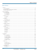
Table of Contents Table of Contents 1. Overview ...............................................................................................................................................................................9 1.1 Initial Configuration........................................................................................................................................................ 10 1.2 Connecting to PCs, Servers, Hubs, and Switches.......................................................
Chapter 1: Overview 3.4 Spanning Tree................................................................................................................................................................63 3.4.1 Bridge Settings....................................................................................................................................................64 3.4.2. MSTI Mapping..................................................................................................................
Chapter 1: Overview 3.13 GVRP.......................................................................................................................................................................... 129 3.13.1 Configuration................................................................................................................................................... 129 3.13.2 Statistics................................................................................................................
Chapter 1: Overview 4.6 AAA ...........................................................................................................................................................................186 4.6.1 Configuration....................................................................................................................................................186 4.6.2 RADIUS Overview..............................................................................................................
Chapter 1: Overview 1 Overview This user’s manual provides step-by-step instructions for configuring and monitoring your Gigabit Managed Switch through the Web via an RJ-45 (serial) interface and Ethernet port. Detailed explanations of hardware and software functions are shown, along with examples of the operation for Web-based interface. The Gigabit Managed Switch, part of the next generation of Web-managed switches from Black Box, provides a reliable infrastructure for your business network.
Chapter 1: Overview 1.1 Initial Configuration This section details how to configure and manage the Gigabit Managed Switch through the Web user interface. This feature enables administrators to easily access and monitor the entire status of the switch through any one port of the switch. Statuses which may be monitored include status of the MIBs, activity of each port, status of spanning trees, port aggregation status, multicast traffic, VLAN and priority status, even illegal access records.
Chapter 1: Overview The login process now is completed. In this login menu, you must input the complete username and password respectively: the Gigabit Managed Switch will not give you a shortcut to username automatically. This may be inconvenient, but it is safer. The Gigabit Managed Switch supports a simple user management function allowing only one administrator to configure the system at the same time.
Chapter 2: System Configuration Figure 1-2. Accessing the on-line help function. Page 12 724-746-5500 | blackbox.
Chapter 2: System Configuration Connecting Network Devices The switch is designed to be connected to 10-, 100-, or 1000-Mbps network cards in PCs and servers, as well as to other switches and hubs. It may also be connected to remote devices using optional SFP transceivers. Twisted-Pair Devices Each device requires an unshielded twisted-pair (UTP) cable with RJ-45 connectors at both ends. Use Category 5, 5e, or 6 cable for 1000BASE-T connections, Category 5 or better for 100BASE-TX connections.
Chapter 2: System Configuration 1.3 Network Wiring Connections Today, the punchdown block is an integral part of many of the newer equipment racks. It is actually part of the patch panel. Instructions for making connections in the wiring closet with this type of equipment follows: Step 1: Attach one end of a patch cable to an available port on the switch, and the other end to the patch panel. Step 2.
Chapter 2: System Configuration 2. System Configuration This chapter describes all of the basic configration tasks, including the system information and any management of the switch (e.g., Time, Account, IP, Syslog, and SNMP). 2.1 System Information After logging in, the switch shows you the system information.
Chapter 2: System Configuration • Contact: Enter the contact person’s name and phone here. You can configure this parameter through the device’s user interface or SNMP. • Device Name: The name of the switch. User-defined. • System Date: Show the system time of the switch. Its format: day of week, month, day, hours : minutes : seconds, year. • System Uptime: The time accumulated since this switch is powered up. Its format is day, hour, minute, second. • BIOS Version: The version of the BIOS in this switch.
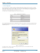
Chapter 2: System Configuration 2.1.2 Configuration You can identify the system by configuring the contact information, name, and location of the switch. Web Interface To configure System Information in the Web interface: 1. Click System, System Information, Configuration. 2. Write System Contact, System Name, System Location information in this page. 3. Click Save. Figure 2-2. System Information Configuration screen.
Chapter 2: System Configuration 2.1.3 CPU Load This page displays the CPU load, using an SVG graph. The load is measured as averaged over the last 100-ms, 1-second, and 10-second intervals. The last 120 samples are graphed, and the last numbers are displayed as text as well. To display the SVG graph, your browser must support the SVG format. Consult the SVG Wiki for more information on browser support.
Chapter 2: System Configuration 2.2 Time This section describes how to configure the switch time, including Time Configuration and NTP Configuration. 2.2.1 Manual The switch provides manual and automatic ways to set the system time via NTP. Manual setting is simple. Input “Year”, “Month”, “Day”, “Hour”, “Minute” and “Second” within the valid value range indicated in each item. Web Interface To configure Time in the Web interface: 1. Click Time, Manual. 2. Specify the Time parameter in manual parameters.
Chapter 2: System Configuration • Daylight Savings Time Set Offset: Daylight savings time is used in some countries. If you select this setting, the unit will adjust the time, forward or backward in increments of one hour, between the starting date and the ending date that you select. For example, if you set the daylight savings offset to be 1 hour, when the time reaches the starting time, the system time will be increased one hour.
Chapter 2: System Configuration 2.2.2 NTP NTP is Network Time Protocol and is used to sync the network time based Greenwich Mean Time (GMT). If you use the NTP mode and select a built-in NTP time server or manually specify an user-defined NTP server as well as Time Zone, the switch will sync the time a short time after pressing yjr button. Although it synchronizes the time automatically, NTP does not update the time periodically without user input. Time Zone is an offset time of GMT.
Chapter 2: System Configuration 2.3.1 Users This page provides an overview of the current users. Currently the only way to log in as another user on the Web server is to close and reopen the browser. Web Interface To configure Account in the Web interface: 1. Click SYSTEM, Account, Users. 2. Click Add new user 3. Specify the User Name parameter. 4. Click Save. Figure 2-6. The Users Account configuration screen. Parameter Description • User Name: The name identifying the user.
Chapter 2: System Configuration 2.3.2 Privilege Levels This section provides an overview of Privilege Levels. The switch enables administrators to set user privileges in a number of different categories, including Account, Aggregation, Diagnostics, EEE, GARP, GVRP, IP, IPMC, Snooping, LACP, LLDP, LLDP, MED, MAC, Table, MRP, MVR, MVRP, Maintenance, Mirroring, PoE, Ports, Private VLANs, QoS, SMTP, SNMP, Security, Spanning Tree, System, Trap Event ,VCL, VLANs, and Voice VLAN Privilege Levels from 1 to 15.
Chapter 2: System Configuration Parameter Description • Group Name The name identifying the privilege group. In most cases, a privilege level group consists of a single module (e.g. LACP, RSTP or QoS), but a few of them contain more than one. The following description defines these privilege level groups in detail: - System: Contact, Name, Location, Timezone, Log.
Chapter 2: System Configuration 2.4 IP (Internet Protocol) IP is an acronym for Internet Protocol. It is a protocol used for communicating data across an Internet network. IP is a "best effort" system, which means that no packet of information sent over is ensured to reach its destination in the same condition it was sent.
Chapter 2: System Configuration Parameter Description • DHCP Client: Enable the DHCP client by checking this box. If DHCP fails and the configured IP address is zero, DHCP will retry. If DHCP fails and the configured IP address is non-zero, DHCP will stop and the configured IP settings will be used. The DHCP client will announce the configured system name as hostname to provide DNS lookup. • IP Address: Provide the IP address of this switch in dotted decimal notation.
Chapter 2: System Configuration 2.4.2 IPV6 This section describes how to configure the switch-managed IPv6 information. The Configured column is used to view or change the IPv6 configuration. And the Current column is used to show the active IPv6 configuration. Configure the switch-managed IPv6 information on this page. The Configured column is used to view or change the IPv6 configuration. The Current column is used to show the active IPv6 configuration.
Chapter 2: System Configuration 2.5 Syslog The Syslog (system log) is a standard for logging program messages. It allows separation of the software that generates messages from the system that stores them and the software that reports and analyzes them. It can also be used for generalized informational, analysis, and debugging messages. It is supported by a wide variety of devices and receivers across multiple platforms. 2.5.
Chapter 2: System Configuration 2.5.2 Log This section describes how to display the System Log Information for the switch. Web Interface To display the log configuration in the Web interface: 1. Click Syslog, Log. 2. Display the log information. Figure 2-11. The System Log Information screen. Parameter Description • Auto-refresh: To set the switch to auto-refresh the log information, check “Auto-refresh.” • Level: level of the system log entry.
Chapter 2: System Configuration 2.5.3 Detailed Log This section describes how to use the Detailed Log Information for the switch. Web Interface To display the detailed log configuration in the Web interface: 1. Click Syslog, Detailed Log. 2. Display the log information. Figure 2-12. The Detailed System Log Information screen. Parameter Description • ID: The ID (>= 1) of the system log entry. • Message: The detailed message of the system log entry. • Icons, upper right of screen (Refresh, clear, ….
Chapter 2: System Configuration 2.6 SNMP Any Network Management System (NMS) running the Simple Network Management Protocol (SNMP) can manage the managed devices equipped with SNMP agent, provided that the Management Information Base (MIB) is installed correctly on the managed devices. The SNMP is a protocol that is used to govern the transfer of information between SNMP manager and agent and traverses the Object Identity (OID) of the management Information Base (MIB), described in the form of SMI syntax.
Chapter 2: System Configuration 2.6.2 Communities This function is used to configure SNMPv3 communities. The Community and UserName are unique. To create a new community account, check button, and enter the account information. Then click . The maximum group number is four. Web Interface To display the configure SNMP Communities in the Web interface: 1. Click SNMP, Communities. 2. Click Add new community. 3. Specify the SNMP communities parameters. 4. Click Save. 5.
Chapter 2: System Configuration 2.6.3 Users The function is used to configure SNMPv3 users. The Entry index key is UserName. To create a new UserName account, check the button, enter the user information, and then check . The maximum number of groups is 10. Web Interface To display the SNMP Users Configuration in the Web interface: 1. Click SNMP, Users. 2. Specify the Privilege parameter. 3. Click Save. Figure 2-15. The SNMP Users Configuration screen.
Chapter 2: System Configuration • Authentication Password: A string identifying the authentication password phrase. For MD5 authentication protocol, the string length should be 8 to 32 ASCII characters from 33 to 126. For SHA authentication protocol, the string length should 8 to 40ASCII characters from 33 to 126. • Privacy Protocol: Indicates the privacy protocol that this entry should belong to. Possible privacy protocols are: - None: No privacy protocol.
Chapter 2: System Configuration 2.6.4 Groups This function is used to configure SNMPv3 group. The Entry index keys are Security Model and Security Name. To create a new group account, please check button, and enter the group information then check . The Maximum Group Number : v1: 2, v2: 2, v3:10. Web Interface To display the configure SNMP Groups in the Web interface: 1. Click SNMP, Groups. 2. Specify the Privilege parameter. 3. Click Save. Figure 2-16.
Chapter 2: System Configuration 2.6.5 Views This function is used to configure SNMPv3 view. The entry index keys are OID Subtree and View Name. To create a new view account, click the button, and enter the view information then check . Max Group Number : 28. Web Interface 1. Click SNMP, Views. 2. Click Add new View. 3. Specify the SNMP View parameters. 4. Click Save. 5. To modify or clear the setting, click Reset. Figure 2-17. The SNMP Views Configuration screen.
Chapter 3: Configuration 2.6.6 Access This function is used to configure SNMPv3 access. The entry index keys are Group Name, Security Model and Security level. To create a new access account, check button, and enter the access information then check . Max Group Number :14 Web Interface To display the configure SNMP Access in the Web interface: 1. Click SNMP, Accesses. 2. Click Add new Access. 3. Specify the SNMP Access parameters. 4. Click Save. 5.
Chapter 3: Configuration • Read View Name: The name of the MIB view defining the MIB objects for which this request may request the current values. The string length should be 1 to 32 characters, using ASCII characters from 33 to 126. • Write View Name: The name of the MIB view defining the MIB objects for which this request may potentially set new values. The string length should be 1 to 32 characters, using ASCII characters from 33 to 126. . 2.6.7 Trap The function is used to configure SNMP trap.
Chapter 3: Configuration • UDP Port: To assign port number. Default: 162 • Community / Security Name: The length of “Community / Security Name” string is restricted to 1–32. • Security Level: Indicates what kind of message will send to the Security Level. Possible modes are: - Info: Send information, warnings, and errors. - Warning: Send warnings and errors. - Error: Send errors. • Security Level: There are three kinds of choices: - NoAuth, NoPriv: No authentication and no privacy.
Chapter 3: Configuration 3. Configuration This chapter describes all the basic network configuration tasks, which include the Ports, Layer 2 network protocol (e.g. VLANs, QoS, IGMP, ACLs and PoE etc.), and any setting of the switch. 3.1 Port This section describes how to configure the Port detail parameters of the switch, including how to configure, enable, or disable the Port, or to monitor the port‘s content or status functionality 3.1.
Chapter 3: Configuration Parameter Description • Port: This is the logical port number for this row. • Link: The current link state is displayed graphically. Green indicates the link is up and red that it is down. • Current Link Speed: Provides the current link speed of the port. • Configured Link Speed: Select any available link speed for the given switch port. - Auto Speed selects the highest speed that is compatible with a link partner. - Disabled disables the switch port operation.
Chapter 3: Configuration 3.1.2 Port Description This section describes how to configure the port’s alias and any descriptions for the Port Identity. It prompts the user to create an alphanumeric string describing the full name and version for the system’s hardware, software version, and networking application. Web Interface To configure an Port Description in the Web interface: 1. Click Configuration, Port, then Port Description. 2.
Chapter 3: Configuration 3.1.3 Traffic Overview This section describes the port statistics information and provides an overview of general traffic statistics for all switch ports. Web Interface To Display the Port Statistics Overview in the Web interface: 1. Click Configuration, Port, then Traffic Overview. 2. To set the unit to auto-refresh, check “Auto-refresh”. 3. Click “Refresh“ to refresh the port statistics or clear all information by clicking “Clear”. Figure 3-3.
Chapter 3: Configuration 3.1.4 Detailed Statistics This section describes how to find detailed traffic statistics for a specific switch port. Use the port select box to select which switch port details to display. The displayed counters are the totals for receive and transmit, the size counters for receive and transmit, and the error counters for receive and transmit. Web Interface To Display the per port detailed port statistics overview in the Web interface: 1.
Chapter 3: Configuration Receive and Transmit Size Counters: The number of (good and bad) packets split into categories that have been received and transmitted based on their respective frame sizes. Receive and Transmit Queue Counters: The number of packets per input and output queue received and transmitted. Receive Queue Counters: • Rx Drops: The number of frames dropped because of lack of receive buffers or egress congestion.
Chapter 3: Configuration 3.1.5 Qos Statistics This section describes how the switch displays the QoS detailed Queuing Counters for a specific switch port for the different queues for all switch ports. Web Interface To Display the Queueing Counters in the Web interface: 1. Click Configuration, Port, then QoS Statistics 2. To auto-refresh the information, check “Auto-refresh”. 3. Click “Refresh“ to refresh the Queueing Counters or clear all information when you click “Clear”. Figure 3-5.
Chapter 3: Configuration 3.1.6 SFP Information This section describes the SFP module detail information, including connector type, fiber type, wavelength, baud rate, and vendor OUI, etc. Web Interface To display the SFP information in the Web interface: 1. Click Configuration, Port, then SFP Information 2. To display the SFP Information. Figure 3-6. The SFP Information Overview screen. Parameter Description • Connector Type: Displays the connector type: UTP, SC, ST, LC etc.
Chapter 3: Configuration 3.1.7 EEE This section enables the user to inspect and configure the current EEE port settings. EEE is a power saving option that reduces the power usage when there is very low traffic utilization (or no traffic). EEE works by powering down circuits when there is no traffic. When a port gets data to be transmitted, all circuits are powered up. The time it takes to power up the circuits is called “wakeup time.
Chapter 3: Configuration Parameter Description EEE Port Configuration: The EEE port settings relate to the currently selected item, as shown in the page header. • Port: The switch port number of the logical EEE port. • EEE Enabled: Controls whether EEE is enabled for this switch port. • EEE Urgent Queues: Queue sets will activate transmition of frames as soon as any data is available. Otherwise the queue will postpone the transmsion until 3000 bytes are ready to be transmitted.
Chapter 3: Configuration 3.2 ACL The Gigabit Managed Switch access control list (ACL) is probably the most commonly used object in the IOS. It is used not only for packet filtering but also for selecting types of traffic to be analyzed, forwarded, or influenced in some way. The ACLs are divided into EtherTypes. IPv4, ARP protocol, MAC and VLAN parameters etc. Here we will go over the standard and extended access lists for TCP/IP. To create ACEs for ingress classification, assign a policy for each port.
Chapter 3: Configuration • Port Copy: Select which port frames are copied on. The values permitted are “Disabled“ or a specific port number. The default value is “Disabled.“ • Mirror: Specify the mirror operation of this port. The permitted values are: - Enabled: Frames received on the port are mirrored. - Disabled: Frames received on the port are not mirrored. The default value is “Disabled“. • Logging: Specify the logging operation of this port.
Chapter 3: Configuration 3.2.2 Rate Limiters This section describes how to configure the switch’s ACL Rate Limiter parameters. The Rate Limiter Levels from 1 to 16 permit the user to set rate limiter value and units with pps or kbps. Web Interface To configure ACL Rate Limiter in the Web interface: 1. Click Configuration, ACL, then Rate Limiter 2. To specific the Rate field and the range from 0 to 3276700. 3. To scroll the Unit with pps or kbps 4. Click the Save button to save the setting 5.
Chapter 3: Configuration 3.2.3 Access Control List This section describes how to configure Access Control List rule. An Access Control List (ACL) is a sequential list of permit or deny conditions that apply to IP addresses, MAC addresses, or other more specific criteria. This switch tests ingress packets against the conditions in an ACL one by one. A packet will be accepted as soon as it matches a permit rule, or dropped as soon as it matches a deny rule. If no rules match, the frame is accepted.
Chapter 3: Configuration Parameter Description • Ingress Port : Indicates the ingress port of the ACE. Possible values are: - Any: The ACE will match any ingress port. - Policy: The ACE will match ingress ports with a specific policy. - Port: The ACE will match a specific ingress port. • Frame Type: Indicates the frame type of the ACE. Possible values are: - Any: The ACE will match any frame type. - Ethernet Type: The ACE will match Ethernet Type frames.
Chapter 3: Configuration • Buttons: - Save: Click to save changes. - Reset: Click to undo any changes made locally and revert to previously saved values. - Cancel: Click to cancel changes. • Auto-refresh: Click to refresh the information automatically. • Icons, upper right of screen (Refresh, Clear, Remove All): Click to refresh the ACL Configuration. Click Clear to reset changes manually. Click Remove All to clean up all ACL configurations on the table. 3.2.
Chapter 3: Configuration - Permit: Frames matching the ACE may be forwarded and learned. - Deny: Frames matching the ACE are dropped. • Rate Limiter: Indicates the rate limiter number of the ACE. The range is 1 to 16. When Disabled is displayed, the rate limiter operation is disabled. • Port Copy: Indicates the port copy operation of the ACE. Frames matching the ACE are copied to the port number. The permitted values are disabled or a specific port number.
Chapter 3: Configuration 3.3 Aggregation The Aggregation is used to configure the settings of Link Aggregation. You can bundle more than one port with the same speed, full-duplex and the same MAC to be a single logical port, thus the logical port aggregates the bandwidth of these ports. This means you can use your current Ethernet equipment to build the bandwidth aggregation.
Chapter 3: Configuration Parameter Description Hash Code Contributors • Source MAC Address: The Source MAC address can be used to calculate the destination port for the frame. Check to enable the use of the Source MAC address or uncheck to disable. By default, Source MAC Address is enabled. • Destination MAC Address: The Destination MAC Address can be used to calculate the destination port for the frame. Check to enable the use of the Destination MAC Address, or uncheck to disable.
Chapter 3: Configuration 3.3.2 LACP Ports using Link Aggregation Control Protocol (according to IEEE 802.3ad specification) as their trunking method can choose their unique LACP GroupID to form a logic “trunked port”. The benefit of using LACP is that a port makes an agreement with its peer port before it becomes a ready member of a “trunk group” (also called aggregator). LACP is safer than the other trunking method, static trunk.
Chapter 3: Configuration • Key: The Key value incurred by the port, range 1-65535. The Auto setting will set the key as appropriate by the physical link speed, 10Mb = 1, 100Mb = 2, 1Gb = 3. Using the Specific setting, a user-defined value can be entered. Ports with the same Key value can participate in the same aggregation group, while ports with different keys cannot. • Role: The Role shows the LACP activity status.
Chapter 3: Configuration Port Status When you set the LACP function on the switch, a Port Status overview for all LACP instances is enabled. Web Interface To display the LACP Port Status in the Web interface: 1. Click Configuration, LACP, Port Status 2. To set the switch to auto-refresh the information, check “Auto-refresh”. 3. Click “Refresh“ to refresh the LACP Port Status. Figure 3-15. The LACP Status screen. Parameter Description • Port: The switch port number.
Chapter 3: Configuration Port Statistics When you complete the LACP function on the switch, a Port Statistics overview for all LACP instances is enabled. Web Interface To display the LACP Port status in the Web interface: 2. To set the switch to auto-refresh the information, check “Auto-refresh”. 3. Click “Refresh“ to refresh the LACP Port Statistics. Figure 3-16. The LACP Statistics screen. Parameter Description • Port: The switch port number.
Chapter 3: Configuration 3.4 Spanning Tree The Spanning Tree Protocol (STP) can be used to detect and disable network loops, and to provide backup links between switches, bridges, or routers. This allows the switch to interact with other bridging devices (that is, an STP-compliant switch, bridge, or router) in your network to ensure that only one route exists between any two stations on the network, and provide backup links which automatically take over when a primary link goes down.
Chapter 3: Configuration 3.4.1 Bridge Settings This section describes how to configure the Spanning Tree Bridge and STP System settings. It allows you to configure STP System settings that are used by all STP Bridge instances in the swtich. Web Interface To configure the Spanning Tree Bridge Settings parameters in the Web interface: 1. Click Configuration, Spanning Tree, Bridge Settings. 2. Scoll to select your parameters and the values in Basic Settings. 3.
Chapter 3: Configuration Advanced Settings • Edge Port BPDU Filtering: Control whether a port explicitly configured as Edge will transmit and receive BPDUs. • Edge Port BPDU Guard: Control whether a port explicitly configured as Edge will disable itself upon reception of a BPDU. The port will enter the error-disabled state, and will be removed from the active topology. • Port Error Recovery: Control whether a port in the error-disabled state automatically will be enabled after a certain time.
Chapter 3: Configuration Parameter Description Configuration Identification • Configuration Name: The name identifying the VLAN to MSTI mapping. Bridges must share the name and revision (see below), as well as the VLAN-to-MSTI mapping configuration to share spanning trees for MSTI's (Intra-region). The name should not exceed 32 characters. • Configuration Revision: The revision of the MSTI configuration named above. This must be an integer between 0 and 65535. MSTI Mapping • MSTI: The bridge instance.
Chapter 3: Configuration Parameter Description • MSTI: The bridge instance. The CIST is the default instance, always active. • Priority: Controls the bridge priority. Lower numeric values have better priority. The bridge priority plus the MSTI instance number, concatenated with the 6-byte MAC address of the switch forms a Bridge Identifier. • Buttons: - Save: Click to save changes. - Reset: Click to undo any changes made locally and revert to previously saved values. 3.4.
Chapter 3: Configuration • Priority: Controls the port priority. This can be used to control priority of ports having identical port cost. (See 3.4.3 MSTI Priorities). • operEdge (state flag): This is the operational flag describing whether the port is connecting directly to edgedevices. (No Bridges attached.) Transition to the forwarding state is faster for edge ports (having operEdge true) than for other ports. The value of this flag is based on AdminEdge and AutoEdge fields.
Chapter 3: Configuration 3.4.5 MSTI Ports This section enables the user to inspect or adjust the current STP MSTI port configuration. An MSTI port is a virtual port, which is represented separately for each active CIST (physical) port for each MSTI instance configured on and applicable to the port. The MSTI instance must be selected before displaying actual MSTI port configuration options. It contains MSTI port settings for physical and aggregated ports.
Chapter 3: Configuration • Priority: Controls the port priority. This can be used to control priority of ports having identical port cost. (See 3.4.3 MSTI Priorities). • Buttons: - Save: Click to save changes. - Reset: Click to undo any changes made locally and revert to previously saved values. 3.4.6 Bridge Status After you complete the MSTI Port configuration, confibure the Bridge Status. This section provides a status overview of all STP bridge instances.
Chapter 3: Configuration 3.4.7 Port Status After you complete the STP configuration, configure the switch display for the STP Port Status. This section enables you to display the STP CIST port status for physical ports of the currently selected switch. Web Interface To display the STP Port status in the Web interface: 1. Click Configuration, Spanning Tree, STP Port Status. 2. To auto-refresh the information, check “Auto-refresh”. 3. Click “Refresh“ to refresh the STP Bridges. 3-24.
Chapter 3: Configuration 3.4.8 Port Statistics After you complete the STP configuration, configure the switch to display the STP Statistics. This section enables you to adjust the STP Statistics detail counters of bridge ports in the currently selected switch. Web Interface To display the STP Port status in the Web interface: 1. Click Configuration, Spanning Tree, Port Statistics 2. To auto-refresh the information, check “Auto-refresh”. 3. Click “Refresh“ to refresh the STP Bridges. Figure 3-25.
Chapter 3: Configuration 3.5 IGMP Snooping This function is used to establish the multicast groups to forward the multicast packet to the member ports, and, in doing so, avoids wasting the bandwidth while IP multicast packets are running over the network. This is because a switch that does not support IGMP or IGMP Snooping cannot tell the multicast packet from the broadcast packet, so it can only treat them all as broadcast packets.
Chapter 3: Configuration Parameter Description • Snooping Enabled: Enable the Global IGMP Snooping. • Unregistered IPMCv4 Flooding Enabled: Enable unregistered IPMCv4 traffic flooding. • IGMP SSM Range: SSM (Source-Specific Multicast) Range allows the SSM-aware hosts and routers to run the SSM service model for the groups in the address range. Format: (IP address/sub mask). • Proxy Enabled: Enable IGMP Proxy.
Chapter 3: Configuration Parameter Description • VLAN ID: It displays the VLAN ID of the entry. • Snooping Enabled: Enable the per-VLAN IGMP Snooping. Only up to 32 VLANs can be selected. • IGMP Querier: Sends IGMP Query messages onto a particular link. Enable the IGMP Querier in the VLAN. • Compatibility: Compatibility is maintained by hosts and routers taking appropriate actions depending on the versions of IGMP operating on hosts and routers within a network.
Chapter 3: Configuration Web Interface To configure the IGMP Snooping Port Group Configuration in the Web interface: 1. Click Configuration, IGMP Snooping, Port Group Filtering 2. Click Add new Filtering Group 3. Scroll the Port to enable the Port Group Filtering. Specify the Filtering Groups in the blank field. 4. Click the Save button to save the setting. 5. To cancel the setting, click the Reset button to revert to previously saved values.
Chapter 3: Configuration 3.5.4 Status After completing the IGMP Snooping configuration, the switch will display the IGMP Snooping Status. This section enables you to view the IGMP Snooping detail status. Web Interface To display the IGMP Snooping status in the Web interface: 1. Click Configuration, IGMP Snooping, Status. 2. If you want to auto-refresh the information, check “Auto-refresh”. 3. Click “Refresh“ to refresh the IGMP Snooping Status. 4. Click “Clear“ to clear the IGMP Snooping Status.
Chapter 3: Configuration 3.5.5 Group Information After setting the IGMP Snooping function, you can view the IGMP Snooping Group Information. Entries in the IGMP Group Table are shown on this page. The IGMP Group Table is sorted first by VLAN ID, and then by group. It will use the last entry of the currently displayed table as a basis for the next lookup. When the end is reached the text “No more entries“ is shown in the displayed table. Use the button to start over.
Chapter 3: Configuration 3.5.6 IPv4 SSM information Source Specific Multicast (SSM) is a datagram delivery model that best supports one-to-many applications, also known as broadcast applications. SSM is a core network technology of IP multicast targeted for audio and video broadcast application environments. For the SSM delivery mode, an IP multicast receiver host must use IGMP Version 3 (IGMPv3) to subscribe to channel (S, G).
Chapter 3: Configuration • Mode: Indicates the filtering mode maintained per (VLAN ID, port number, Group Address) basis. It can be either Include or Exclude. • Source Address: The IP Address of the source. Currently, system limits the total number of IP source addresses for filtering to 128. • Type: Indicates the Type. It can be either Allow or Deny. • Auto-refresh: To set the unit to auto-refresh the information, check the “auto-refresh“ box.
Chapter 3: Configuration 3.6 MLD Snooping Curiously enough, a network node that acts as a source of IPv6 multicast traffic is only an indirect participant in MLD snooping— it just provides multicast traffic, and MLD doesn’t interact with it. (Note, however, that in an application like desktop conferencing a network node may act as both a source and an MLD host; but MLD interacts with that node only in its role as an MLD host.
Chapter 3: Configuration Figure 3-33. The MLD Snooping Basic Configuration screen. Parameter Description • Snooping Enabled: Enables the Global MLD Snooping. • Unregistered IPMCv6 Flooding Enabled: Enable unregistered IPMCv6 traffic flooding. Please note that disabling unregistered IPMCv6 traffic flooding may lead to failure of Neighbor Discovery.
Chapter 3: Configuration 3.6.2 VLAN Configuration When MLD snooping is enabled on a VLAN, the switch acts to minimize unnecessary multicast traffic. If the switch receives multicast traffic destined for a given multicast address, it forwards that traffic only to ports on the VLAN that have MLD hosts for that address. It drops that traffic for ports on the VLAN that have no MLD hosts. The switch will use the last entry of the currently displayed entry as a basis for the next lookup.
Chapter 3: Configuration • Icons, upper right of screen (Refresh, <<, >> ): Click “Refresh“ to refresh the IGMP Group Status manually; click the arrows to navigaate to the next page or entry. • Buttons: - Save: Click to save changes. - Reset: Click to undo any changes made locally and revert to previously saved values. 3.6.3 Port Group Filtering This section describes how to set Port Group Filtering for the MLD Snooping function to add new groups and safety policies.
Chapter 3: Configuration 3.6.4 Status This section describes how to display the MLD Snooping Status. Web Interface To display the MLD Snooping Status in the Web interface: 1. Click Configuration, MLD Snooping, Status 2. If you want to auto-refresh the information, check “Auto-refresh” 3. Click “Refresh“ to refresh the MLD Snooping Status information. 4. Click “Clear“ to clear the MLD Snooping Status window. 3-36. The MLD Snooping Status screen. Parameter Description • VLAN ID: The VLAN ID of the entry.
Chapter 3: Configuration 3.6.5 Group Information This section describes how to set MLD Snooping Groups Information. The “Start from VLAN“, and “group“ input fields allow the user to select the starting point in the MLD Group Table. Each page shows up to 99 entries from the MLD Group table, default being 20, selected through the “entries per page“ input field. When first visited, the Web page will show the first 20 entries from the beginning of the MLD Group Table.
Chapter 3: Configuration 3.6.6 IPv6 SSM Information This section describes how to configure the entries in the MLDv2 Information Table. The MLDv2 Information Table is sorted first by VLAN ID, then by group, and then by Port No. Different source addresses belonging to the same group are treated as a single entry. Each page shows up to 64 entries from the MLDv2 SSM (Source Specific Multicast) Information table, the default being 20, selected through the “entries per page“ input field.
Chapter 3: Configuration 3.7 MVR The MVR feature enables multicast traffic forwarding on the Multicast VLAN. In a multicast television application, a PC or a television with a set-top box can receive the multicast stream. Multiple set-top boxes or PCs can be connected to one subscriber port, which is a switch port configured as an MVR receiver port. When a subscriber selects a channel, the set-top box or PC sends an IGMP join message to Switch A to join the appropriate multicast.
Chapter 3: Configuration 3.7.2 Groups Information This section describes how to display the MVR Groups detail information on the switch. Entries in the MVR Group Table are shown on this page. The MVR Group Table is sorted first by VLAN ID, and then by group. Web Interface To display the MVR Groups Information in the Web interface: 1. Click Configuration, MVR, Groups Information. 2. To set the unit to auto-refresh the information, check the “Auto-refresh” box. 3. Click “Refresh“ to refresh the information.
Chapter 3: Configuration 3.7.3 Statistics This section describes the switch will display the MVR detail statistics after you had configured MVR on the switch. It provides the detail MVR statistics information. Web Interface To display the MVR statistics information in the Web interface: 1. Click Configuration, MVR, Statistics. 2. To set the unit to auto-refresh the information, check the “Auto-refresh” box. 3. Click “Refresh“ to refresh the information. 4.
Chapter 3: Configuration 3.8 LLDP The switch supports the LLDP. For current information on your switch model, the Link Layer Discovery Protocol (LLDP) provides a standards-based method for enabling switches to advertise themselves to adjacent devices and to learn about adjacent LLDP devices.
Chapter 3: Configuration • Tx Delay: If some configuration is changed (e.g. the IP address) a new LLDP frame is transmitted, but the time between the LLDP frames will always be at least the value of Tx Delay seconds. Tx Delay cannot be larger than 1/4 of the Tx Interval value. Valid values are restricted to one to 8192 seconds.
Chapter 3: Configuration 3.8.2 LLDP Neighbors This page provides a status overview for all LLDP neighbors. The displayed table contains a row for each port on which an LLDP neighbor is detected. The columns hold the following information: Web Interface To show LLDP neighbors: 1. Click LLDP Neighbors. 2. Click Refresh for manual update Web screen. 3. Click Auto-refresh for auto-update Web screen. Figure 3-43: The LLDP Neighbor information screen.
Chapter 3: Configuration • System Description: System Description is the port description advertised by the neighbor unit. • Management Address: Management Address is the neighbor unit’s address that is used for higher layer entities to assist discovery by the network management. This could hold the neighbor's IP address, for example. • Auto-refresh: Check the auto-refresh box to set the unit to refresh information automatically.
Chapter 3: Configuration Figure 3-44. The LLDP-MED Configuration screen. Figure 3-45 The LLDP-MED Configuration Policies screen . Parameter Description Fast start repeat count The Rapid startup and Emergency Call Service Location Identification Discovery of endpoints are critically important aspects of VoIP systems.
Chapter 3: Configuration Parameter Description: Coordinates Location • Latitude: Latitude should be normalized to within 0-90 degrees with a maximum of 4 digits. It is possible to specify the direction to either north of the equator or south of the equator. • Longitude: Longitude should be normalized to within 0-180 degrees with a maximum of 4 digits. It is possible to specify the direction to either east of the prime meridian or west of the prime meridian.
Chapter 3: Configuration • Apartment: Unit (Apartment, suite) - Example: Apt 42. • Floor: Floor - Example: 4. • Room no.: Room number - Example: 450F. • Place type: Place type - Example: Office. • Postal community name: Example: Leonia. • P.O. Box: Post office box (P.O. BOX) - Example: 12345. • Additional code: Example: 1320300003. • Emergency Call Service: (e.g. E911 and others), such as defined by TIA or NENA.
Chapter 3: Configuration • Application Type: Intended use of the application types: 1. Voice - for use by dedicated IP telephony handsets and similar appliances supporting interactive voice services. These devices are typically deployed on a separate VLAN for ease of deployment and enhanced security by isolation from data applications. 2. Voice Signaling (conditional) - for use in network topologies that require a different policy for the voice signaling than for the voice media.
Chapter 3: Configuration 3.8.4 LLDP-MED Neighbors This section provides a status overview of all LLDP-MED neighbors. The table contains a row for each port on which an LLDP neighbor is detected. This function applies to VoIP devices that support LLDP-MED. Web Interface To show LLDP-MED neighbor: 1. Click LLDP-MED Neighbor. 2. Click Refresh for manual update Web screen. 3. Click Auto-refresh for auto-update Web screen.
Chapter 3: Configuration • LLDP-MED Generic Endpoint (Class I): The LLDP-MED Generic Endpoint (Class I) definition is applicable to all endpoint products that require the base LLDP discovery services defined in TIA-1057, however do not support IP media or act as an end-user communication appliance. Such devices may include (but are not limited to) IP Communication Controllers, other communication related servers, or any device requiring basic services as defined in TIA-1057.
Chapter 3: Configuration 7. Streaming Video - for use by broadcast or multicast-based video content distribution and other similar applications supporting streaming video services that require specific network policy treatment. Video applications relying on TCP with buffering would not be an intended use of this application type. 8. Video Signaling - for use in network topologies that require a separate policy for the video signaling than for the video media.
Chapter 3: Configuration 3.8.5 EEE By using EEE, power savings can be achieved at the expense of traffic latency. This latency occurs because EEE circuits turn off to save power, and they need time to boot up before sending traffic over the link. This time is called “wakeup time“. To achieve minimal latency, devices can use LLDP to exchange information about their respective tx and rx “wakeup time“ as a way to agree upon the minimum wakeup time they need.
Chapter 3: Configuration 3.8.6 Port Statistics Two types of counters are shown. Global counters are counters that refer to the whole switch, while local counters refer to per-port counters for the currently selected switch. Web Interface To show LLDP Statistics: 1. Click LLDP, than click Port Statistics to show LLDP counters. 2. Click Refresh to see the manual update Web screen. 3. Click Auto-refresh to see the auto-update Web screen. 4. Click Clear to clear all counters.
Chapter 3: Configuration • Frames Discarded: If an LLDP frame is received on a port, and the switch’s internal table has run full, the LLDP frame is counted and discarded. This situation is known as “Too Many Neighbors“ in the LLDP standard. LLDP frames require a new entry in the table when the Chassis ID or Remote Port ID is not already contained within the table. Entries are removed from the table when a given port’s link is down, an LLDP shutdown frame is received, or when the entry times out.
Chapter 3: Configuration 3.9 Filtering Data Base The Filtering Data Base Configuration function gathers many functions, including MAC Table Information, Static MAC Learning, which cannot be categorized to some function type. MAC Table The switching of frames is based upon the DMAC address contained in the frame. The switch builds up a table that maps MAC addresses to switch ports for knowing which ports the frames should go to (based upon the DMAC address in the frame).
Chapter 3: Configuration Figure 3-49: The MAC Address Table Configuration screen. Parameter Description • Aging Configuration: By default, dynamic entries are removed from the MAC table after 300 seconds. This removal is also called aging. Configure aging time by entering a value here in seconds. For example, Age time seconds. The range given should be 10 to 1,000,000 seconds. Disable the automatic aging of dynamic entries by checking Disable Automatic Aging.
Chapter 3: Configuration Static MAC Table Configuration The static entries in the MAC table are shown in this table. The static MAC table can contain 64 entries. The MAC table is sorted first by VLAN ID and then by MAC address. • Delete: Check to delete the entry. It will be deleted during the next save. • VLAN ID: The VLAN ID of the entry. • MAC Address: The MAC address of the entry. • Port Members: Checkmarks indicate which ports are members of the entry. Check or uncheck as needed to modify the entry.
Chapter 3: Configuration 3.9.2 Dynamic MAC Table Entries in the MAC Table are shown on this page. The MAC Table contains up to 8192 entries and is sorted first by VLAN ID then by MAC address. Web Interface To Display MAC Address Table in the Web interface: 1. Click Dynamic MAC Table. 2. Specify the VLAN and MAC Address. 3. Display MAC Address Table. Figure 3-50. The Dynamic MAC Address Table information screen.
Chapter 3: Configuration 3.10 VLAN This section describes how to assign a specific VLAN for management purpose. The management VLAN is used to establish an IP connection to the switch from a workstation connected to a port in the VLAN. This connection supports a VSM, SNMP, and Telnet session. By default, the active management VLAN is VLAN 1, but you can designate any VLAN as the management VLAN by configuring System->IP->IPv4->VLAN ID. Only one management VLAN can be active at a time. Figure 3-51.
Chapter 3: Configuration 3.10.1 VLAN Membership The VLAN membership configuration for the selected switch can be monitored and modified here. Up to 4094 VLANs are supported. This page allows for adding and deleting VLANs as well as adding and deleting port members of each VLAN. Web Interface To configure VLAN membership configuration in the Web interface: 1. Click VLAN Membership Configuration. 2. Specify a Management VLAN ID from 1~ 4094. 3. Click Save. Figure 3-52.
Chapter 3: Configuration 3.10.2 Ports User can configure all parameters to each port in VLAN Port Setting. These parameters involved two parts, Ingress rule and Egress rule. The function of Port Type, Ingress Filtering, Frame Type, and PVID affect Ingress process. Furthermore, Port Type, Egress Rule, and PVID affect Egress process. Web Interface To configure VLAN Port configuration in the Web interface: 1. Click VLAN Port Configuration. 2. Specify the VLAN Port Configuration parameters. 3. Click Save.
Chapter 3: Configuration Table 3-1: Port Types. Port Type Unaware: The function of Unaware can be used for 802.1QinQ (double tag). Ingress Action Egress Action When the port received untagged frames, an untagged frame obtains a tag (based on PVID) and is forwarded. The TPID of a frame transmitted by an Unaware port will be set to 0x8100. When the port received tagged frames, 1. if the tagged frame with TPID=0x8100, it becomes a double-tag frame, and is forwarded. 2.
Chapter 3: Configuration 3.10.3 Switch Status The function Switch Status gathers the information of all VLAN status and reports it by the order of Static NAS MVRP MVP Voice VLAN MSTP GVRP Combined. Web Interface To Display VLAN membership status in the Web interface: 1. Click VLAN membership. 2. Specify the Staic NAS MVRP MVP Voice VLAN MSTP GVRP Combined. 3. Display membership information. Figure 3-54. The VLAN Membership Status for Combined Users screen.
Chapter 3: Configuration 3.10.4 Port Status This function, Port Status, gathers the information of all VLAN status and reports it by the order of Static NAS MVRP MVP Voice VLAN MSTP GVRP Combined. Web Interface To Display VLAN Port Status in the Web interface: 1. Click VLAN Port Status. 2. Specify the Static NAS MVRP MVP Voice VLAN MSTP GVRP Combined. 3. Display Port Status information. Figure 3-55. The VLAN Port Status for Static User screen.
Chapter 3: Configuration 3.10.5 Private VLANs In a private VLAN, communication between ports is not permitted. A VLAN can be configured as a private VLAN. Assigning Membership in Private VLANs The Private VLAN membership configurations for the switch can be monitored and modified here. Private VLANs can be added or deleted here. Port members of each Private VLAN can be added or removed here. Private VLANs are based on the source port mask, and there are no connections to VLANs.
Chapter 3: Configuration Port Isolation Port Isolation provides for an apparatus and method to isolate ports on Layer 2 switches on the same VLAN to restrict traffic flow. The apparatus comprises a switch having said plurality of ports, each port configured as a protected port or a non-protected port. An address table memory stores an address table having a destination address and port number pair.
Chapter 3: Configuration 3.10.6 MAC-Based VLAN MAC address-based VLAN decides the VLAN for forwarding an untagged frame based on the source MAC address of the frame. A most common way of grouping VLAN members is by port, hence the name port-based VLAN. Typically, the device adds the same VLAN tag to untagged packets that are received through the same port. Later on, these packets can be forwarded in the same VLAN.
Chapter 3: Configuration Parameter Description • Delete: To delete a MAC-based VLAN entry, check this box and press Save. The entry will be deleted on the selected switch. • MAC Address: Indicates the MAC address. • VLAN ID: Indicates the VLAN ID. • Port Members: A row of checkboxes for each port is displayed for each MAC-based VLAN entry. To include a port in a MACbased VLAN, check the box. To remove or exclude the port from the MAC-based VLAN, make sure the box is unchecked.
Chapter 3: Configuration Status This section shows MAC-based VLAN entries configured by various MAC-based VLAN users. Currently we support following VLAN User types: NAS : NAS provides port-based authentication, which involves communications between a Supplicant, Authenticator, and an Authentication Server. Web Interface To Display MAC-based VLAN configured in the Web interface: 1. Click MAC-based VLAN Status. 2. Specify the Static NAS Combined. 3. Display MAC-based information. Figure 3-59.
Chapter 3: Configuration 3.10.7 Protocol-Based VLAN This section describes Protocol-based VLAN. The switch supports protocol including Ethernet LLC SNAP Protocol. LLC The Logical Link Control (LLC) data communications protocol layer is the upper sub-layer of the Data Link Layer (which is itself Layer 2, just above the Physical Layer) in the seven-layer OSI reference model.
Chapter 3: Configuration Parameter Description • Delete: To delete a Protocol to Group Name map entry, check this box. The entry will be deleted on the switch during the next Save. • Frame Type: Frame Type can have one of the following values: 1. Ethernet 2. LLC 3. SNAP NOTE: When you change the Frame type field, the valid value of the following text field will vary depending on the new frame type you selected.
Chapter 3: Configuration Group to VLAN This section has instructions on how to map an already-configured Group Name to a VLAN for the selected switch. Web Interface To Display Group Name to VLAN mapping table configured in the Web interface: 1. Click Group Name VLAN configuration and add new entry. 2. Specify the Group Name and VLAN ID. 3. Click Save. Figure 3-61. The Group Name of VLAN Mapping Table screen. Parameter Description • Delete: To delete a Group Name to VLAN map entry, check this box.
Chapter 3: Configuration 3.11 Voice VLAN Voice VLAN is VLAN configured specially for voice traffic. By adding the ports with voice devices attached to voice VLAN, we can perform QoS-related configuration for voice data, ensuring the transmission priority of voice traffic and voice quality. 3.11.1 Configuration The Voice VLAN feature enables voice traffic forwarding on the Voice VLAN, then the switch can classify and schedule network traffic.
Chapter 3: Configuration Parameter Description • Mode: Indicates the Voice VLAN mode operation. Disable the MSTP feature before enabling Voice VLAN to avoid the conflict of ingress filtering. Possible modes are: Enabled: Enable Voice VLAN mode operation. Disabled: Disable Voice VLAN mode operation. • VLAN ID: Indicates the Voice VLAN ID. This should be a unique VLAN ID in the system and cannot equal each port PVID. It is a conflict in configuration if the value equals management VID, MVR VID, PVID etc.
Chapter 3: Configuration 3.11.2 OUI This section describes how to Configure the VOICE VLAN OUI table. The maximum entry number is 16. Modifying the OUI table will restart auto detection of OUI process. Web Interface To configure Voice VLAN OUI Table in the Web interface: 1. Select “Add new entry”, then check ”Delete” in the Voice VLAN OUI table. 2. Specify Telephony OUI, Description. 3. Click Save. Figure 3-63. The Voice VLAN OUI Table screen. Parameter Description • Delete: Check to delete the entry.
Chapter 3: Configuration 3.12 GARP The Generic Attribute Registration Protocol (GARP) provides a generic framework in which devices in a bridged LAN, e.g. end stations and switches, can register and de-register attribute values, such as VLAN Identifiers, with each other. In doing so, the attributes are propagated to devices in the bridged LAN, and these devices form a reachability tree that is a subset of an active topology.
Chapter 3: Configuration • Timer Values: To set the GARP join timer, leave timer, and leave all timers, the unit is microseconds (ms). Three different timers can be configured on this page: - Join Timer: The default value for Join timer is 200 ms. - Leave Timer: The range of values for Leave Time is 600–1000 ms. The default value for Leave Timer is 600 ms. - Leave All Timer: The default value for Leave All Timer is 10000 ms. • Application: Currently only supported application is GVRP.
Chapter 3: Configuration 3.12.2 Statistics This section describes the port statistics of GARP for all switch ports. The port statistics relate to the currently selected unit, as shown in the page header. Web Interface To display GARP Port statistics in the Web interface: 1. Click GARP statistics. 2. Scroll to the port you want to display the GARP Counter information. 3. Click Refresh to modify the GARP statistics information. Figure 3-65. The GARP Port Statistics screen.
Chapter 3: Configuration 3.13 GVRP GVRP is an application based on Generic Attribute Registration Protocol (GARP), mainly used to automatically and dynamically maintain the group membership information of the VLANs. The GVRP offers the function providing the VLAN registration service through a GARP application.
Chapter 3: Configuration 1. GVRP Mode This configuration is to enable/disable GVRP Mode on particular port locally. - Disable: Select to disable GVRP Mode on this port. - Enable: Select to enable GVRP Mode on this port. The default value of configuration is Disable. 2. GVRP rrole This configuration is used to configure restricted role on an interface. - Disable: Select to disable GVRP rrole on this port. - Enable: Select to enable GVRP rrole on this port. The default configuration is Disable.
Chapter 3: Configuration 3.13.2 Statistics The section describes the basic GVRP Port statistics for all switch ports. The statistics relate to the currently selected unit, as shown in the page header. Web Interface To display GVRP Port statistics in the Web interface: 1. Click GVRP statistics. 2. Scroll to the port you want to display the GVRP Counter information. 3. Click Refresh to modify the GVRP statistics information. Figure 3-67. The GVRP Port Statistics screen.
Chapter 3: Configuration 3.14 QoS The switch supports four QoS queues per port, with strict or weighted fair queuing scheduling. It supports QoS Control Lists (QCL) for advance programmable QoS classification, based on IEEE 802.1p, Ethertype, VID, IPv4/IPv6 DSCP and UDP/TCP ports and ranges. High flexibility in the classification of incoming frames to a QoS class.
Chapter 3: Configuration • DP level: Controls the default DP level, i.e., the DP level for frames not classified in any other way. • PCP: Controls the default PCP for untagged frames. • DEI: Controls the default DEI for untagged frames. • Tag Class: Shows the classification mode for tagged frames on this port. - Disabled: Use default QoS class and DP level for tagged frames. - Enabled: Use mapped versions of PCP and DEI for tagged frames. Click on the mode to configure the mode and/or mapping.
Chapter 3: Configuration 3.14.2 Port Policing This section provides an overview of QoS Ingress Port Policers for all switch ports. Because voice and video usually maintain a steady rate of traffic, Port Policing is useful in constraining traffic flows and marking frames above specific rates. Web Interface To display the QoS Port Schedulers in the Web interface: 1. Click Configuration, QoS, Port Policing. 2.
Chapter 3: Configuration 3.14.3 Port Scheduler This section provides an overview of QoS Egress Port Schedulers for all switch ports. and the ports belong to the currently selected unit, as stated in the screen header. Web Interface To display the QoS Port Schedulers in the Web interface: 1. Click Configuration, QoS, Port Schedulers. 2. Display the QoS Egress Port Schedulers. Click the Port Index to set the QoS Egress Port Schedulers. Figure 3-70.
Chapter 3: Configuration Selecting “Weighted“ mode will display this screen instead of that shown in Figure 3-65. Figure 3-71. The QoS Egress Port Scheduler front screen in Weighted mode. Parameter Description • Port: The logical port for the settings contained in the same row. Click on the port number to configure the schedulers. • Mode: Shows the scheduling mode for this port. • Weight (Qn): Shows the weight for this queue and port.
Chapter 3: Configuration 3.14.4 Port Shaping This section provides an overview of QoS Egress Port Shaping for all switch ports. Others the user could get all detail information ot the ports belong to the currently selected unit, as shown in the page header. Web Interface To display the QoS Port Shapers screen in the Web interface: 1. Click Configuration, QoS, Port Shapers. 2. Display the QoS Egress Port Shapers. Click the Port Index to set the QoS Egress Port Shapers Figure 3-72.
Chapter 3: Configuration Selecting “Weighted“ mode will display this screen instead of that shown in Figure 3-65. Figure 3-73. The QoS Egress Port Shapers screen, Weighted mode. Parameter Description • Port: The logical port for the settings contained in the row. Click on the port number to configure the shapers. • Shapers (Qn): Shows “disabled“ or actual queue shaper rate, e.g. “800 Mbps.“ • Shapers (Port): Shows “disabled“ or actual port shaper rate, e.g. “800 Mbps.
Chapter 3: Configuration 3.14.5 Port Tag Remarking This section provides an overview of QoS Egress Port Tag Remarking for all switch ports. Others the ports belong to the currently selected unit, as shown in the screen header. Web Interface To display the QoS Port Tag Remarking in the Web interface: Click Configuration, QoS, Port Tag Remarking. Click the Port Index to set the QoS Port Tag Remarking. Figure 3.74 The Port Tag Remarking screen.
Chapter 3: Configuration 3.14.6 Port DSCP The section describes how to set the QoS Port DSCP configuration, enabling you to configure the basic QoS Port DSCP Configuration settings for all switch ports. Others the settings relate to the currently selected unit, as shown in the page header. Web Interface To configure the QoS Port DSCP parameters in the Web interface: 1. Click Configuration, QoS, Port DSCP. 2. Evoke to enable or disable the Ingress Translate and Scroll the Classify Parameter configuration.
Chapter 3: Configuration • Egress: Port Egress Rewriting can be one of these parameters: - Disable: No Egress rewrite. - Enable: Rewrite enable without remapped. - Remap: DSCP from analyzer is remapped and frame is remarked with remapped DSCP value. • Buttons: - Save: Click to save changes. - Reset: Click to undo any changes made locally and revert to previously saved values. 3.14.
Chapter 3: Configuration Figure 3-76. The DSCP-Based QoS Ingress Classification Configuration screen. Parameter Description • DSCP: Maximum number of supported DSCP values are 64. • Trust: Click to check if the DSCP value is trusted. • QoS Class: QoS Class value can be any of (0-7). • DPL: Drop Precedence Level (0-3). • Buttons: - Save: Click to save changes. - Reset: Click to undo any changes made locally and revert to previously saved values. Page 142 724-746-5500 | blackbox.
Chapter 3: Configuration 3.14.8 DSCP Translation This section describes how you can configure the basic QoS DSCP Translation settings for all switches. DSCP Translation can be done in Ingress or Egress. Web Interface To configure the DSCP Translation parameters in the Web interface: 1. Click Configuration, QoS, DSCP Translation. 2. Scroll to set the Ingress Translate and Egress Remap DP0 and Remap DP1 Parameters. 3. Evoke to enable or disable Classify. 4. Click the Save button to save the setting. 5.
Chapter 3: Configuration Parameter Description • DSCP: Maximum number of supported DSCP values are 64, and valid DSCP value ranges from 0 to 63. • Ingress: The Ingress side DSCP can be first translated to new DSCP before using the DSCP for QoS class and DPL map. There are two configuration parameters for DSCP translation: 1. Translate : DSCP at Ingress side can be translated to any of (0–63) DSCP values. 2. Classify : Click to enable Classification at Ingress side.
Chapter 3: Configuration 3.14.9 DSCP Classification This section describes how to configure and map DSCP value to a QoS Class and DPL value. Others the settings relate to the currently selected unit, as shown in the page header. Web Interface To configure the DSCP Classification parameters in the Web interface: 1. Click Configuration, QoS, DSCP Translation. 2. Scroll to set the DSCP Parameters. 3. Click the Save button to save the setting. 4.
Chapter 3: Configuration 3.14.10 QoS Control List Configuration This section shows the QoS Control List (QCL), which is made up of the QCEs. Each row describes a QCE that is defined. The maximum number of QCEs is 256 on each switch. Click on the lowest plus sign to add a new QCE to the list. Web Interface To configure the QoS Control List parameters in the Web interface: 1. Click Configuration, QoS, QoS Contol List. 2. Click the to add a new QoS Control List. 3.
Chapter 3: Configuration • SMAC: Displays the OUI field of Source MAC address, i.e. first three octet (byte) of MAC address. • DMAC: Specify the type of Destination MAC addresses for incoming frame. Possible values are: Any: All types of Destination MAC addresses are allowed. Unicast: Only Unicast MAC addresses are allowed. Multicast: Only Multicast MAC addresses are allowed. Broadcast: Only Broadcast MAC addresses are allowedd. The default value is “Any.
Chapter 3: Configuration DMAC Type Destination MAC type: possible values are unicast (UC), multicast (MC), broadcast (BC) or ’Any.’ Frame Type can have any of the following values: 1. Any 2. Ethernet 3. LLC 4. SNAP 5. IPv4 6. IPv6 All frame types are explained below: 1. Any: Allow all types of frames. 2. Ethernet: A valid Ethernet type can have a value within 0x600-0xFFFF or ’Any.’ The default value is ’Any.’ 3. LLC: A valid SSAP (Source Service Access Point) can vary from 0x00 to 0xFF or ’Any’.
Chapter 3: Configuration 3.14.11 QCL Status This section describes how to configure the QCL status by different QCL users. Each row describes the QCE that is defined. It is a conflict if a specific QCE is not applied to the hardware because of hardware limitations. The maximum number of QCEs is 256 on each switch. Web Interface To display the QoS Control List Status in the Web interface: 1. Click Configuration, QoS , QCL Status. 2. To Auto-refresn information, check “Auto-refresh”. 3.
Chapter 3: Configuration • Auto-refresh: Check the auto-refresh box to set the unit to refresh information automatically. • Resolve Conflict: Click it to resolve confict issues. • Icon, upper right of screen (Refresh): Click to refresh the QCL information manually. 3.14.12 Storm Control This section describes how to configure the Storm control for the switch. There is a unicast storm rate control, multicast storm rate control, and a broadcast storm rate control. These only affect flooded frames, i.e.
Chapter 3: Configuration 3.15 Thermal Protection This section describes how to inspect and configure current settings for controlling thermal protection. Thermal protection is used to protect the chip from becoming overheated. 3.15.1 Configuration When the temperature exceeds the configured thermal protection temperature, ports will be turned off to decrease the power consumption. It is possible to arrange the ports with different priorities.
Chapter 3: Configuration NOTE: The temperature means the MAC and PHY chipset’s TA temperature, not the PSU device or environment temperature. Do not set environment temperature limitation value. • Port priorities: This indicates the priority for each port. It allows the user to set what priority criterion is used to trigger the Port to be turned off via thermal protection. • Buttons: - Save: Click to save changes. - Reset: Click to undo any changes made locally and revert to previously saved values. 3.15.
Chapter 3: Configuration 3.16 sFlow Agent The sFlow Collector configuration for the switch can be monitored and modified here. Up to one Collector is supported. This section contains instructions on how to configure sFlow collector IP type, sFlow collector IP Address, and Port Number for each sFlow Collector. 3.16.1 sFlow Collector The “Current“ field displays the currently configured sFlow Collector. The “Configured“ field displays the new Collector Configuration.
Chapter 3: Configuration • Time out: It is the duration during which the collector receives samples, Once it is expired, the sampler stops sending the samples. It is through the management the value is set before it expires. The value accepted is within the range of 0-2147483647. By default it is set to 0. • Datagram Size: The maximum UDP datagram size to send out the sFlow samples to the receiver. The value accepted is within the range of 200-1500 bytes. The default is 1400 bytes.
Chapter 3: Configuration Parameter Description • sFlow Ports: List of the port numbers on which sFlow is configured. • sFlow Instance: Configured sFlow instance for the port number. • Sampler Type: Configured sampler type on the port and could be any of the types: None, Rx, Tx or All. Scroll to choose. By default, The value is “None”. • Sampling Rate: Configured sampling rate on the ports. • Max Hdr Size: Configured size of the header of the sampled frame.
Chapter 3: Configuration 3.17 Loop Protection Loop detection detects the presence of traffic. When a switch becomes aware that a packet’s (looping detection frame) MAC address is the same that of its own port, Loop Protection activates. The port will be locked when it receives the looping detection frames. To resume the locked port, locate and remove the looping path, select the locked port and click on “Resume“. 3.17.1 Configuration To set Loop Protection.
Chapter 3: Configuration • Action: Configures the action performed when a loop is detected on a port. Valid values are Shutdown Port, Shutdown Port and Log or Log Only. • Tx Mode: Controls whether the port is actively generating loop protection PDUs, or whether it is just passively looking for looped PDUs. • Buttons: - Save: Click to save changes. - Reset: Click to undo any changes made locally and revert to previously saved values. 3.17.
Chapter 3: Configuration 3.18 Single IP Single IP Management (SIM) is a simple and useful method to optimize network utilities and management, designed to manage a group of switches as a single entity, called a SIM group. The SIM feature will enable users to: - Simplify management of small workgroups or wiring closets while scaling networks to handle increased bandwidth demand. - Reduce the number of IP addresses needed on the network.
Chapter 3: Configuration Web Interface To show the Single IP in the Web interface: 1. Click Configuration, Single IP, and then Information. 2. Click refresh, or check auto-refresh to automaticaly update Information. Figure 3-89. The Single IP Information screen. Parameter Description • Index: Indicates how many slave devices connect to the SIP group. • Model name: Indicates what kind device has joined this SIP group.
Chapter 3: Configuration 3.19 Easy Port Easy Port provides a convenient way to save and share common configurations. Use it to enable features and settings based on the location of a switch in the network and for mass configuration deployments across the network, including Voice IP phones, wireless access points and IP cameras, Or leverage it to run a converged voice, video, and data network considering quality of service (QoS), bandwidth, latency, and high performance.
Chapter 3: Configuration • Port Security limit: Set the Port security limit here. The default is 1. • Spanning Tree Admin Edge: Enable or disable the Spanning Tree Admin Edge function. • Spanning Tree BPDU Guard: Enable or disable the Spanning Tree BPDU Guard function on the Easy Port. • Buttons: - Save: Click to save changes. - Reset: Click to undo any changes made locally and revert to previously saved values. LGB1108A 724-746-5500 | blackbox.
Chapter 3: Configuration 3.20 Mirroring You can mirror traffic from any source port to a target port for real-time analysis. You can then attach a logic analyzer or RMON probe to the target port and study the traffic crossing the source port in a completely unobtrusive manner. The Mirror Configuration enables you to monitor the traffic of the network.
Chapter 3: Configuration 3.21 Trap Event Severity This function is used to set a Alarm trap and get the Event log. The Trap Events Configuration function is used to enable the switch to send out the trap information while pre-defined trap events occurred. Web Interface To configure the Trap Event Severity Configuration in the Web interface: 1. Click Configuration, Trap Event Severity Configuration. 2. Scroll to select the Group name and Severity Level. 3. Click Save to save the setting. 4.
Chapter 3: Configuration 3.22 SMTP Configuration When the switch perceives an alarm, use this function to enable the SMTP server to send you an alarm e-mail. Web Interface To configure the SMTP Configuration in the Web interface: 1. Click Configuration, SMTP Configuration. 2. Scroll to select the Severity Level. 3. Specify the parameters in each blank field. 4. Click the Save button to save the setting. 5. Click Reset to undo any changes made locally and revert to previously saved values Figure 3-93.
Chapter 3: Configuration 3.23 UPnP Universal Plug and Play (UPnP) enables devices to connect seamlessly and to simplify the implementation of networks in home (data sharing, communications, and entertainment) and corporate environments. Web Interface To configure the UPnP Configuration in the Web interface: 1. Click Configuration, UPnP. 2. Scroll to select the mode to enable or disable. 3. Specify the parameters in each blank field. 4. Click Save to save the setting. 5.
Chapter 4: Security 4. Security This chapter describes all the switch security configuration tasks to enhance the security of the local network including IP Source Guard, ARP Inspection, DHCP Snooping, AAA, and others. 4.1. IP Source Guard This section describes how to configure the IP Source Guard detail parameters of the switch. Use the IP Source Guard Configuration screen to configure to enable or disable with the port of the switch. 4.1.
Chapter 4: Security Parameter Description • Mode of IP Source Guard Configuration: Enable the Global IP Source Guard or disable the Global IP Source Guard. All configured ACEs will be lost when the mode is enabled. • Port Mode Configuration: Specify on which ports IP Source Guard is enabled. Only when both Global Mode and Port Mode on a given port are enabled is IP Source Guard enabled on that port. • Max Dynamic Clients: Specify the maximum number of dynamic clients that can be learned on given port.
Chapter 4: Security • IP Mask: Used for calculating the allowed network with IP address. • MAC address: Valid source MAC address. • Adding new entry: Click to add a new entry to the Static IP Source Guard table. Specify the Port, VLAN ID, IP address, and IP Mask for the new entry. Click “Save.“ • Buttons: - Save: Click to save changes. - Reset: Click to undo any changes made locally and revert to previously saved values. 4.1.
Chapter 4: Security 4.2 ARP Inspection The section describes to configure the ARP Inspection parameters of the switch. Use the ARP Inspection configure to manage the ARP table. 4.2.1 Configuration This section describes how to configure ARP Inspection setting including: - Mode (Enabled and Disabled). - Port (Enabled and Disabled). Web Interface To configure an ARP Inspection Configuration in the Web interface 1. Select “Enabled” in the Mode of ARP Inspection Configuration. 2.
Chapter 4: Security 4.2.2 Static Table This section describes how to configure the Static ARP Inspection Table parameters of the switch. Web Interface To configure a Static ARP Inspection Table Configuration in the Web interface: 1. Click “Add new entry”. 2. Specify the Port, VLAN ID, IP Address, and MAC address in the entry. 3. Click “Save.“ Figure 4-5. The Static ARP Inspection Table Parameter Description • Delete: Check to delete the entry. It will be deleted during the next save.
Chapter 4: Security 4.2.3 Dynamic Table This section describes how to configure the Dynamic ARP Inspection Table parameters. The Dynamic ARP Inspection Table contains up to 1024 entries, and is sorted first by port, then by VLAN ID, then by MAC address, and then by IP address. Web Interface To configure a Dynamic ARP Inspection Table Configuration in the Web interface: 1. Specify the Start from port, VLAN ID, MAC Address, IP Address, and entries per page. 2. Check “Auto-refresh”. Figure 4-6.
Chapter 4: Security 4.3 DHCP Snooping The section describes how to configure the DHCP Snooping parameters of the switch, for the purpose of preventing attackers from adding their own DHCP servers to the network. 4.3.1 Configuration This section describes how to configure the DHCP Snooping setting including: - Snooping Mode (Enabled and Disabled) - Port Mode Configuration (Trusted, Untrusted) Web Interface To configure DHCP Snooping in the Web interface: 1.
Chapter 4: Security 4.3.2 Statistics This section describes how to display the DHCP snooping port statistics. The statistics show only packet counters when DHCP snooping mode is enabled and relay mode is disabled. They don’t count the DHCP packets for a DHCP client. Web Interface To configure DHCP Snooping Statistics in the Web interface: 1. Specify the Port which you want to monitor. 2. Check “Auto-refresh”. Figure 4-8. DHCP Snooping Port Statistics screen.
Chapter 4: Security 4.4 DHCP Relay The section describes how to forward DHCP requests to another specific DHCP servers via DHCP relay. The DHCP servers may be on another network. 4.4.1 Configuration This section describes how to configure DHCP Relay setting including: - Relay Mode (Enabled and Disabled) - Relay Server IP setting - Relay Information Mode (Enabled and Disabled) - Relay Information Mode Policy (Replace, Keep and Drop) Web Interface To configure a DHCP Relay in the Web interface: 1.
Chapter 4: Security • Relay Information Policy: Indicates the DHCP relay information option policy. When DHCP relay information mode operation is enabled, if agent receives a DHCP message that already contains relay agent information, it will enforce the policy. And it only works under DHCP if relay information operation mode is enabled. Possible policies are: - Replace:Replace the original relay information when a DHCP message that already contains it is received.
Chapter 4: Security Client Statistics • Transmit to Client: The number of relayed packets from server to client. • Transmit Error: The number of packets that resulted in error while being sent to servers. • Receive from Client: The number of received packets from server. • Receive Agent Option: The number of received packets with relay agent information option. • Replace Agent Option: The number of packets which were replaced with relay agent information option.
Chapter 4: Security 4.5 NAS This section describes how to configure the NAS parameters of the switch. The NAS server can be used to connect users to a variety of resources including Internet access, conference calls, printing documents on shared printers, or by simply logging on to the Internet. 4.5.1 Configuration This section describes how to configure the NAS setting of the IEEE 802.1X, MAC-based authentication system and port settings.
Chapter 4: Security Parameter Description • Mode: Indicates if NAS is globally enabled or disabled on the switch. If globally disabled, all ports are allowed forwarding of frames. • Reauthentication Enabled: If checked, successfully authenticated supplicants/clients are reauthenticated after the interval specified by the Reauthentication Period. Reauthentication for 802.1X-enabled ports can be used to detect if a new device is plugged into a switch port or if a supplicant is no longer attached.
Chapter 4: Security • RADIUS-Assigned VLAN Enabled: RADIUS-assigned VLAN provides a means to centrally control the VLAN on which a successfully authenticated supplicant is placed on the switch. Incoming traffic will be classified to and switched on the RADIUSassigned VLAN. The RADIUS server must be configured to transmit special RADIUS attributes to take advantage of this feature (see RADIUS-Assigned VLAN Enabled below for a detailed description).
Chapter 4: Security NOTE: Suppose two backend servers are enabled and that the server timeout is configured to X seconds (using the AAA configuration page), and suppose that the first server in the list is currently down (but not considered dead).
Chapter 4: Security The advantage of MAC-based authentication over port-based 802.1X is that several clients can be connected to the same port (e.g. through a third party switch or a hub) and still require individual authentication, and that the clients don't need special supplicant software to authenticate. The advantage of MAC-based authentication over 802.1X-based authentication is that the clients don't need special supplicant software to authenticate.
Chapter 4: Security - Value of Tunnel-Type must be set to "VLAN" (ordinal 13). - Value of Tunnel-Private-Group-ID must be a string of ASCII characters in the range '0' - '9', which is interpreted as a decimal string representing the VLAN ID. Leading '0's are discarded. The final value must be in the range [1; 4095].
Chapter 4: Security Reinitialize: Forces a reinitialization of the clients on the port—and thereby a reauthentication—immediately. The clients will transfer to the unauthorized state while the reauthentication is in progress. • Buttons: - Save: Click to save changes. - Reset: Click to undo any changes made locally and revert to previously saved values. • Icon, upper right of screen (Refresh): Click to refresh the NAS Configuration information manually. 4.5.
Chapter 4: Security 4.5.3 Port Status This section provides detailed informationon how to display NAS statistics for a specific switch port running EAPOL-based IEEE 802.1X authentication. Web Interface To configure a NAS Port Status Configuration in the Web interface: 1. Specify the Port you want to check. 2. Check “Auto-refresh”. Figure 4-13. The NAS Statistics screen. Parameter Description Port State • Admin State: The port’s current administrative state.
Chapter 4: Security - Multi 802.1X - MAC-based Auth. • Last Supplicant/Client Info: Information about the last supplicant/client that attempted to authenticate. This information is available for the following administrative states: - Port-based 802.1X - Single 802.1X - Multi 802.1X - MAC-based Auth. Selected Counters • Selected Counters: The Selected Counters table is visible when the port is in one of the following administrative states: • Multi 802.1X • MAC-based Auth.
Chapter 4: Security 4.6 AAA This section shows you how to use an AAA (Authentication, Authorization, Accounting) server to provide access control to your network. The AAA server can be a TACACS+ or RADIUS server to create and manage objects that contain settings for using AAA servers. 4.6.1 Configuration This section describes how to configure an AAA setting of TACACS+ or RADIUS server. Web Interface To configure a Common Configuration of AAA in the Web interface: 1. Set Timeout (Default is 15 seconds).
Chapter 4: Security Figure 4-15. The TACACS+ Authorization and Accounting Configuration screen. Figure 4-16. The RADIUS Authentication Configuration screen. Figure 4-17. The RADIUS Accounting Configuration screen. Figure 4-18. The TACACS+ Authentication Configuration screen. LGB1108A 724-746-5500 | blackbox.
Chapter 4: Security Parameter Description • Timeout: The Timeout, which can be set to a number between 3 and 3600 seconds, is the maximum time to wait for a reply from a server. If the server does not reply within this timeframe, we will consider it to be dead and continue with the next enabled server (if any). RADIUS servers are using the UDP protocol, which is unreliable by design. In order to cope with lost frames, the timeout interval is divided into 3 subintervals of equal length.
Chapter 4: Security • Port: The TCP port to use on the TACACS+ Authentication Server. If the port is set to 0 (zero), the default port (49) is used on the TACACS+ Authentication Server. • Secret: The secret—up to 29 characters long—shared between the TACACS+ Authentication Server and the switch. • Buttons: - Save: Click to save changes. - Reset: Click to undo any changes made locally and revert to previously saved values. 4.6.
Chapter 4: Security - Disabled: The server is disabled. - Not Ready: The server is enabled, but IP communication is not yet up and running. - Ready: The server is enabled, IP communication is up and running, and the RADIUS module is ready to accept accounting attempts. - Dead (X seconds left): Accounting attempts were made to this server, but it did not reply within the configured timeout. The server has temporarily been disabled, but will get reenabled when the dead-time expires.
Chapter 4: Security 4.7 Port Security This section demonstrates how to configure the Port Security settings of the Switch. Use the Port Security feature to restrict input to an interface by limiting and identifying MAC addresses. 4.7.1 Limit Control This section demonstrates how to configure the Port Security settings of the Switch. Use the Port Security feature to restrict input to an interface by limiting and identifying MAC addresses.
Chapter 4: Security • Aging Enabled: If checked, secured MAC addresses are subject to aging as discussed under Aging Period. • Aging Period: If Aging Enabled is checked, then the aging period is controlled with this input. If other modules are using the underlying port security for securing MAC addresses, they may have other requirements to the aging period. The underlying port security will use the shorter requested aging period of all modules that use the functionality.
Chapter 4: Security - Shutdown: Indicates that the port is shut down by the Limit Control module. This state can only be shown if Action is set to Shutdown or Trap & Shutdown. • Re-open Button: If a port is shutdown by this module, you may reopen it by clicking this button, which will only be enabled if this is the case. For other methods, refer to Shutdown in the Action section. NOTE: That clicking the reopen button causes the page to be refreshed, so unsaved changes will be lost.
Chapter 4: Security • Port Status: The table has one row for each port on the selected switch and a number of columns, which are: • Port: The port number for which the status applies. Click the port number to see the status for this particular port. • Users: Each of the user modules has a column that shows whether that module has enabled Port Security or not.
Chapter 4: Security 4.7.3 Port Status This section shows the MAC addresses secured by the Port Security module. Port Security is a module with no direct configuration. Configuration comes indirectly from other modules, including the user modules. When a user module has enabled port security on a port, the port is set up for software-based learning.
Chapter 4: Security 4.8 Access Management This section shows how to configure access management table of the Switch including HTTP/HTTPS, SNMP, and TELNET/SSH. You can manage the Switch over an Ethernet LAN, or over the Internet. 4.8.1 Configuration This section shows how to configure access management table of the switch. The maximum entry number is 16. If the application’s type matches any one of the access management entries, it will allow access to the switch.
Chapter 4: Security • TELNET/SSH: Indicates that the host can access the switch from TELNET/SSH interface if the host IP address matches the IP address range provided in the entry. • Buttons: - Save: Click to save changes. - Reset: Click to undo any changes made locally and revert to previously saved values. 4.8.2 Statistics This section shows you a detailed statistics of the Access Management including HTTP, HTTPS, SSH. TELNET, ans SSH.
Chapter 4: Security 4.9 SSH This section shows how to use SSH (Secure SHell) to securely access the Switch. SSH is a secure communication protocol that combines authentication and data encryption to provide secure encrypted communication. Web Interface To configure a SSH Configuration in the Web interface: 1. Select “Enabled” in the Mode of SSH Configuration. 2. Click “Save.“ Figure 26. The SSH Configuration screen: Parameter Description • Mode: Indicates the SSH mode operation.
Chapter 4: Security 4.10 HTTPS This section shows how to use HTTPS to securely access the Switch. HTTPS is a secure communication protocol that combines authentication and data encryption to provide secure encrypted communication via the browser. Web Interface To configure a HTTPS Configuration in the Web interface: 1. Select “Enabled” in the Mode of HTTPS Configuration. 2. Select “Enabled” in the Automatic Redirect of HTTPS Configuration. 3. Click “Save.“ Figure 4-27.
Chapter 4: Security 4.11 Authentication Method This section shows how to configure a user with authentication when logging in to the switch via one of the management client interfaces. Web Interface To configure a Authentication Method Configuration in the Web interface: 1. Specify the Client (Console, Telnet, SSH, Web) you want to monitor. 2. Specify the Authentication Method (None, Local, RADIUS, TACACS+) 3. Check “Fallback.“ 4. Click “Save.“ Figure 4-28. Authentication Method Configuration screen.
Chapter 5: Maintenance 5. Maintenance This chapter describes all the switch Maintenance configuration tasks to enhance the performance of local network including Restart Device, Firmware upgrade, Save/Restore, Import/Export, and Diagnostics. 5.1 Restart Device This section describes how to restart the switch for any maintenance needs. Any configuration files or scripts saved in the switch should still be available after restart.
Chapter 5: Maintenance 5.2 Firmware This section describes how to upgrade firmware. The switch can be enhanced with more value-added functions by installing firmware upgrades. 5.2.1 Firmware Upgrade This page facilitates an update of the firmware controlling the switch. Web Interface To configure a Firmware Upgrade Configuration in the Web interface: 1. Navigate within the Browser to select firmware in your device. 2. Click “Upload.“ Figure 5-2.
Chapter 5: Maintenance 5.2.2 Firmware Selection The switch supports dual images for firmware redundancy. You can select the firmware image for your device: Start firmware or Operating firmware. This page provides information about the active and alternate (backup) firmware images in the device, and enables you to revert to the alternate image. Web Interface To configure a Firmware Selection in the Web interface: 1. Click “Activate Alternate Image.“ 2. Click “OK“ to complete firmware selection. Figure 5-3.
Chapter 5: Maintenance 5.3 Save / Restore This section describes how to save and restore the switch configuration including reset to Factory Defaults, Save Start, Save Users, Restore Users for any maintenance needs. 5.3.1 Factory Defaults This section describes how to reset the Switch configuration to Factory Defaults. Any configuration files or scripts will recover to factory default values. Web Interface To configure a Factory Defaults Configuration in the Web interface: 1. Click Factory Defaults. 2.
Chapter 5: Maintenance 5.3.2 Save Start This section describes how to save the Switch Start configuration. Any current configuration files will be saved as XML format. Web Interface To configure a Save Start Configuration in the Web interface: 1. Click “Save Start.“ 2. Click “Yes.“ Figure 5-5. The Save Start configuration screen. Parameter Description • Buttons: - Save: Click to save changes. 5.3.3 Save User This section describes how to save users’ information.
Chapter 5: Maintenance 5.3.4 Restore User This section describes how to restore user information back to the switch. Any current configuration files will be restored via XML format. Web Interface To configure a Restore User Configuration in the Web interface: 1. Click “Restore User.“ 2. Click “Yes.“ Figure 5-7. The Restore Backup Configuration screen. Parameter Description • Buttons: - Save: Click to save changes. Page 206 724-746-5500 | blackbox.
Chapter 5: Maintenance 5.4 Export / Import This section describes how to export and import the switch configuration. Any current configuration files will be exported as XML format. 5.4.1 Export Config This section describes how to export the switch configuration for maintenance needs. Any current configuration files will be exported as XML format. Web Interface To configure a Export Config Configuration in the Web interface: 1. Click “Save configuration.“ 2. Save the file in your device. Figure 5-8.
Chapter 5: Maintenance 5.4.2 Import Config This section describes how to import the switch configuration for maintenance needs. Any current configuration files will be imported as XML format. Web Interface To configure an Import Configuration in the Web interface: 1. Click “Browser to select the config file in your device.“ 2. Click “Upload.“ Figure 5-9. The Import Configuration screen. Parameter Description • Browse: Click the “Browse...” button to search the Configuration URL and filename.
Chapter 5: Maintenance 5.5 Diagnostics This section provides a set of basic system diagnotsics. It lets users know that whether the system is healthy or needs to be fixed. The basic system check includes ICMP Ping, ICMPv6, and VeriPHY Cable Diagnostics. 5.5.1 Ping This section allows you to issue ICMP PING packets to troubleshoot IPv6 connectivity issues. Web Interface To configure an ICMP PING Configuration in the Web interface: 1.Specify ICMP PING IP Address. 2.Specify ICMP PING Size. 3.Click “Start.
Chapter 5: Maintenance 5.5.2 Ping6 This section enables you to issue ICMPv6 PING packets to troubleshoot IPv6 connectivity issues. Web Interface To configure an ICMPv6 PING Configuration in the web interface: 1.Specify ICMPv6 PING IP Address. 2.Specify ICMPv6 PING Size. 3.Click “Start.“ Figure 5-11. The ICMPv6 Ping screen. Parameter Description • IP Address: The destination IP Address with IPv6. • Ping Size: The payload size of the ICMP packet. Values range from 8 bytes to 1400 bytes.
Chapter 5: Maintenance 5.5.3 VeriPHY This section describes how to run the VeriPHY Cable Diagnostics. Press to run the diagnostics. It takes approximately five seconds to run. If all ports are selected, it can take approximately 15 seconds. When completed, the page refreshes automatically, and you can view the cable diagnostics results in the cable status table. Note that VeriPHY is only accurate for cables of lengths between 30" and 459" (7–140 meters).
Appendix Appendix: Glossary of Web-Based Management Terms ACE: ACE is an acronym for Access Control Entry. It describes access permission associated with a particular ACE ID. There are three ACE frame types (Ethernet Type, ARP, and IPv4) and two ACE actions (permit and deny). The ACE also contains many detailed, different parameter options that are available for individual application. ACL: ACL is an acronym for Access Control List.
Appendix CCM: CCM is an acronym for Continuity Check Message. It is a OAM frame transmitted from a MEP to its peer MEP and used to implement CC functionality. CDP: CDP is an acronym for Cisco Discovery Protocol. DEI: DEI is an acronym for Drop Eligible Indicator. It is a 1-bit field in the VLAN tag. DES: DES is an acronym for Data Encryption Standard. It provides a complete description of a mathematical algorithm for encrypting (enciphering) and decrypting (deciphering) binary coded information.
Appendix DSCP: DSCP is an acronym for Differentiated Services Code Point. It is a field in the header of IP packets for packet classification purposes. EEE: EEE is an abbreviation for Energy Efficient Ethernet defined in IEEE 802.3az. EPS: EPS is an abbreviation for Ethernet Protection Switching defined in ITU/T G.8031. Ethernet Type: Ethernet Type, or EtherType, is a field in the Ethernet MAC header, defined by the Ethernet networking standard.
Appendix IMAP is the protocol that IMAP clients use to communicate with the servers, and SMTP is the protocol used to transport mail to an IMAP server. The current version of the Internet Message Access Protocol is IMAP4. It is similar to Post Office Protocol version 3 (POP3), but offers additional and more complex features. For example, the IMAP4 protocol leaves your e-mail messages on the server rather than downloading them to your computer.
Appendix MEP: MEP is an acronym for Maintenance Entity Endpoint and is an endpoint in a Maintenance Entity Group (ITU-T Y.1731). Mirroring: For debugging network problems or monitoring network traffic, the switch system can be configured to mirror frames from multiple ports to a mirror port. (In this context, mirroring a frame is the same as copying the frame.) Both incoming (source) and outgoing (destination) frames can be mirrored to the mirror port.
Appendix Policer: A policer can limit the bandwidth of received frames. It is located in front of the ingress queue. POP3: POP3 is an acronym for Post Office Protocol version 3. It is a protocol for e-mail clients to retrieve e-mail messages from a mail server. POP3 is designed to delete mail on the server as soon as the user has downloaded it. However, some implementations allow users or an administrator to specify that mail be saved for some period of time.
Appendix SNAP: The SubNetwork Access Protocol (SNAP) is a mechanism for multiplexing, on networks using IEEE 802.2 LLC, more protocols than can be distinguished by the 8-bit 802.2 Service Access Point (SAP) fields. SNAP supports identifying protocols by Ethernet type field values; it also supports vendor-private protocol identifier. SNMP: SNMP is an acronym for Simple Network Management Protocol. It is part of the Transmission Control Protocol/Internet Protocol (TCP/IP) protocol for network management.
Appendix UDP provides two services not provided by the IP layer. It provides port numbers to help distinguish different user requests and, optionally, a checksum capability to verify that the data arrived intact. Common network applications that use UDP include the Domain Name System (DNS), streaming media applications such as IPTV, Voice over IP (VoIP), and Trivial File Transfer Protocol (TFTP). User Priority: User Priority is a 3-bit field storing the priority level for the 802.1Q frame.
Black Box Tech Support: FREE! Live. 24/7. Tech support the way it should be. Great tech support is just 30 seconds away at 724-746-5500 or blackbox.com. About Black Box Black Box provides an extensive range of networking and infrastructure products. You’ll find everything from cabinets and racks and power and surge protection products to media converters and Ethernet switches all supported by free, live 24/7 Tech support available in 30 seconds or less. © Copyright 2012. Black Box Corporation.