AUGUST 2000 ME800A ME800A-R2 ME805-C ME805-C-R2 ME810 Short-Haul Modem B (SHM-B Async) MAL NOR BACK LOOP RD TD ASY HOR NC S T MO HAUL DEM CUSTOMER SUPPORT INFORMATION Order toll-free in the U.S.: Call 877-877-BBOX (outside U.S. call 724-746-5500) FREE technical support 24 hours a day, 7 days a week: Call 724-746-5500 or fax 724-746-0746 Mailing address: Black Box Corporation, 1000 Park Drive, Lawrence, PA 15055-1018 Web site: www.blackbox.com • E-mail: info@blackbox.
SHM-B ASYNC FEDERAL COMMUNICATIONS COMMISSION AND INDUSTRY CANADA RADIO FREQUENCY INTERFERENCE STATEMENTS This equipment generates, uses, and can radiate radio frequency energy and if not installed and used properly, that is, in strict accordance with the manufacturer’s instructions, may cause interference to radio communication.
SHM-B ASYNC NORMAS OFICIALES MEXICANAS (NOM) ELECTRICAL SAFETY STATEMENT INSTRUCCIONES DE SEGURIDAD 1. Todas las instrucciones de seguridad y operación deberán ser leídas antes de que el aparato eléctrico sea operado. 2. Las instrucciones de seguridad y operación deberán ser guardadas para referencia futura. 3. Todas las advertencias en el aparato eléctrico y en sus instrucciones de operación deben ser respetadas. 4. Todas las instrucciones de operación y uso deben ser seguidas. 5.
SHM-B ASYNC 10. El equipo eléctrico deber ser situado fuera del alcance de fuentes de calor como radiadores, registros de calor, estufas u otros aparatos (incluyendo amplificadores) que producen calor. 11. El aparato eléctrico deberá ser connectado a una fuente de poder sólo del tipo descrito en el instructivo de operación, o como se indique en el aparato. 12. Precaución debe ser tomada de tal manera que la tierra fisica y la polarización del equipo no sea eliminada. 13.
SHM-B ASYNC TRADEMARKS USED IN THIS MANUAL Any trademarks mentioned in this manual are acknowledged to be the property of the trademark owners.
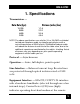
SHM-B ASYNC 1. Specifications Transmission — Data Rate (bps) 19,200 9600 4800 2400 Distance (miles/km) 1/1.6 2/3.2 3/4.8 4/6.4 NOTE:The above specifications are valid for 24- or 26-AWG unshielded twisted-pair telephone cable insulated by polyethylene with a mutual capacitance of 0.083 µf/mile. Shielded twisted-pair cable will reduce the distance to one-third of the table value, due to the additional capacitance contributed by the cable’s shielding.
SHM-B ASYNC end of the loop. Interface is switch-selectable for DTE/DCE configuration (pins 2 and 3 are reversed) Connectors — (1) DB25 female, (1) 5-screw terminal block Diagnostics — Loopbacks provided by a front-panel switch: Analog loopback on a 4-wire loop and digital loopback on equipment interface (EIA-232) Status Indication — Two bi-color LEDs indicate the status of the transmitter and receiver.
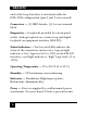
SHM-B ASYNC Primary: 115 VAC ±10%, 60 Hz, 5 watts (12 watts max.); Primary: 230 VAC ±10%, 50/60 Hz; Secondary: 17 VAC, 700 mA Size — Standalone: 1.4"H x 4.25"W x 4.5"D (3.8 x 10.9 x 11.7 cm); Rackmount: 5.25"H x 17"W x 9"D (13 x 43 x 23 cm) Weight — Standalone: 1.3 lb. (0.6 kg), including transformer; Rackmount: 3.7 lb. (1.
SHM-B ASYNC 2. Introduction The Short-Haul Modem Model B Async (SHM-B Async) is an asynchronous full-duplex 4-wire line driver/receiver which allows two EIA-232 devices to communicate at distances of up to 4 miles and at data speeds of up to 19,200 bps. In addition to the transmitter and receiver circuits, the SHM-B Async includes EIA-232 control line interfaces, status monitor LEDs, and a loopback switch. The SHM-B is available in both a standalone version (ME800A) and a rackmount version (ME805-C).
SHM-B ASYNC 3. Installation Installation involves three basic steps: four-wire connections; EIA-232 connection; switch settings. 3.1 Four-Wire Connections Figure 1 shows the location of the terminal block on the circuit board. Refer to Figure 2 to make the proper connections between two SHM-B units. NOTE: Transmit + (TX+) on one modem is wired to Receive + (RX+) on the other modem; Transmit (TX-) is wired to Receive - (RX-). A ground connection is optional. 1.
SHM-B ASYNC 5. Insert the wires into the terminal strip; tighten the screw terminals. 6. After you have made all four connections, wrap the nylon cable tie (packaged with the SHM-B) around the wires. Pull the tie tight around the wires to secure them to the printed circuit board. Trim the excess nylon tie with wire cutters or scissors. J1 RS-232 CONNECTOR EN JUMPER DIS RTS/DTR DCE CONTROL DTE/DCE RX+ RXTX+ TXGROUND DTE S2 (LOOPBACK) Figure 1. SHM-B board; 5-screw terminal block.
SHM-B ASYNC TX+ RX+ TX- RX- RX+ TX+ RX- TX- SHM #1 SHM #2 Figure 2. Wiring diagram for two SHM-B units. 3.2 EIA-232 Connection Connect the SHM-B to your computer or terminal with a standard EIA-232 cable and DB25 connectors. Refer to your equipment’s installation manual if you need information on the exact EIA-232 signals required for your equipment.
SHM-B ASYNC Table 1. EIA-232 Pin Connections on SHM-B Pin Number 1 2 3 4 5 6 7 8 20 Signal Name Protective Ground Transmit Data/Receive Data (TD/RD)* Receive Data/Transmit Data (RD/TD)* Request to Send (RTS) Clear to Send (CTS) Data Set Ready (DSR) Signal Ground Carrier Detect (CD) Data Terminal Ready (DTR) *TD and RD can be reversed using the DTE/DCE switch, S1 on the circuit board. See Section 3.3 for details. 3.3 Switch Settings Refer to Figure 1 in this chapter.
SHM-B ASYNC information concerning its DTE/DCE setting. Table 2 gives the EIA-232 pinning of the SHM-B with the DTE/DCE switch in the DCE position. Table 2. Pinning with DTE/DCE switch in the DCE position.
SHM-B ASYNC 3.4 Flow Control The SHM-B uses a clever, yet simple way to allow this unit to work with a broad line of equipment. STANDARD EIA-232C HANDSHAKING (RTS/DTR CONTROL JUMPER IN EN POSITION) The individual SHM-B modems force their own DTR, RTS, CTS, and DSR control lines HIGH (>+3V) when: • The twisted-pair wires are installed correctly. • Power is applied to both modems. • No computer devices are attached to the modems.
SHM-B ASYNC Because DTR, DSR, RTS, and CTS are tied together internally, dropping any one of these four signals to a negative state will also drop DCD on the remote side to a negative state. DCD will also go LOW if the remote SHM-B is powered down, or if the twisted-pair wire is broken. X-ON/X-OFF MODE (RTS/DTR CONTROL JUMPER IN DIS POSITION) If X-ON/X-OFF characters are used for handshaking control, rather than hardware logic levels, move the RTS/DTR control jumper to the DIS position.
SHM-B ASYNC 4. Operation After completing the wiring and configuration procedure, slide the printed circuit card back into the case while pulling the data and power cables through the holes in the back panel. The front panel will snap into the front of the case when the printed circuit board has been completely pushed to the back of the case. Connect the SHM-B to your equipment, then plug the wall transformer into its power source.
SHM-B ASYNC When in loopback mode, the switch button indicator will appear to the sender. If a CRT terminal is connected to the SHM-B, typing characters on the keyboard should result in the same characters appearing on the CRT screen. If no characters appear, check your EIA-232 connections and the setting of S1. See Figure 3 for an illustration of the loopback mode. The TD and RD LEDs on the front panel of your SHM-B indicate the status of the SHM-B transmitter and receiver, respectively.
SHM-B ASYNC 5. Rackmount Installation The SHM-B Async Card is a rack mount unit (ME805-C) that installs in a standard 19-inch panel rack. (You can use the SHM-B Rack [ME810], which can hold up to 16 cards.) The SHM-B Async Card will occupy 5.25 inches of vertical rack space, and is 9 inches deep. To install the SHM-B Rack, first remove the acrylic front panel by pulling out the six plunger latches on the front of the panel, then pulling on opposite-side plungers to loosen and remove the panel.
SHM-B ASYNC easiest access to the terminals, switches, etc. After a SHM-B Card is wired, it can then be inserted into an open slot in the SHM-B rack. Be certain that the circuit board has mated with the power pins on the SHM-B rack before applying force to fully seat the board; otherwise you may damage the board and power pins. When all boards have been wired and plugged into the rack, plug the wall transformer into its power source. You should be able to communicate as described in Chapter 4.
SHM-B ASYNC 6. Troubleshooting Guide The following information will help you troubleshoot your installation if problems develop. If your particular situation isn’t listed here, call Technical Support for assistance. Have ready a description of the problem with your installation, your DTE equipment make and models, your equipment’s DTE/DCE configuration and flow control type (hardware or software), your EIA-232 cable pinouts, and what (if anything) you have already done to correct the situation.
SHM-B ASYNC printed circuit board is properly inserted and fully seated against the motherboard of the rack. SYMPTOM: No data transfer in one or both directions (to, from, or to-and-from the SHM-B). 1. Monitor the TD LED on the sending-end modem while sending data. The light should flash red/green. If not, check the DCE/DTE switch on that unit. Once you get a TD LED flashing on that unit, simultaneously the RD LED should flash on the other SHM-B unit. If not, go to step 2. 2.
SHM-B ASYNC Pins 4, 5, 6, 8, and 20 should all be HIGH to enable communication. 5. If pin 8 (Carrier Detect) is low, this indicates: • a defective transmission line or connection • a defective remote SHM-B • remote SHM-B without power SYMPTOM: TD and RD LEDs indicate data activity, but data communication doesn’t exist. 1. Check the wiring of the EIA-232 port. Refer to Section 3.2 for information. 2. Check the setting of S1. Refer to Section 3.3 for information.
SHM-B ASYNC computing equipment for consistency. 3. Wire the SHM-B units back-to-back, eliminating the twisted-pair; see if you still have errors. • If you do have errors, then test each SHM individually in the following way: loopback one SHM’s Transmit-to-Receive by using two short pieces of wire. Connect that SHM to a dumb terminal and key in characters; look for a good loopback. A good loopback verifies a SHM-B in proper working condition.
SHM-B ASYNC 3. Check the path of your four-wire circuit for potential sources of interference (fluorescent lighting, electrical motors, etc.). Such sources of electrical “noise” can provide an environment in which unwanted signals are induced onto your four-wire circuit. Also, check to see if an adjacent four-wire cable carrying a separate data stream is creating “crosstalk.
SHM-B ASYNC SYMPTOM: TD or RD indicator is steadily on red with no data attempting to pass (no DTEs attached). Check for reversal of polarity on the four-wire connection.
© Copyright 2000. Black Box Corporation. All rights reserved.