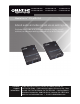
VX-HDMI-POE-MTX VX-HDMI-POE-MRX VX-HDMI-POE-UTX VX-HDMI-POE-URX VX-HDMI-POE-VTX.. VX-HDMI-POE-VRX MediaCento™ IPX with PoE Extend audio and video signals via an existing LAN. BLACK BOX ® Distribute HDMI video to an unlimited number of displays using IP multicast, or make eye-catching video walls of up to 8 x 8 displays. Customer Support Information Order toll-free in the U.S.: Call 877-877-BBOX (outside U.S.
Trademarks Used in this Manual Trademarks Used in this Manual Black Box and the Double Diamond logo are registered trademarks, and MediaCento is a trademark, of BB Technologies, Inc. Bonjour and Apple are registered trademarks of Apple, Inc. Windows is a registered trademark of Microsoft Corporation. UL is a registered trademark of Underwriters’ Laboratories. Any other trademarks mentioned in this manual are acknowledged to be the property of the trademark owners. Page 2 724-746-5500 | blackbox.
FCC RFI Statement FEDERAL COMMUNICATIONS COMMISSION AND INDUSTRY CANADA RADIO FREQUENCY INTERFERENCE STATEMENTS This equipment generates, uses, and can radiate radio-frequency energy, and if not installed and used properly, that is, in strict accordance with the manufacturer’s instructions, may cause interference to radio communication.
NOM Statement 4. Todas las instrucciones de operación y uso deben ser seguidas. 5. El aparato eléctrico no deberá ser usado cerca del agua—por ejemplo, cerca de la tina de baño, lavabo, sótano mojado o cerca de una alberca, etc. 6. El aparato eléctrico debe ser usado únicamente con carritos o pedestales que sean recomendados por el fabricante. 7. El aparato eléctrico debe ser montado a la pared o al techo sólo como sea recomendado por el fabricante. 8.
NOM Statement 16. El cable de corriente deberá ser desconectado del cuando el equipo no sea usado por un largo periodo de tiempo. 17. Cuidado debe ser tomado de tal manera que objectos liquidos no sean derramados sobre la cubierta u orificios de ventilación. 18.
Table of Contents Table of Contents 1. Specifications................................................................................................... 8 2. Overview .................................................................................................. 10 2.1 Introduction........................................................................................... 10 2.2 Available Models................................................................................... 10 2.3 Features..........
Table of Contents 7. Video Wall Features.......................................................................................36 8. Troubleshooting.............................................................................................43 8.1 Problems/Solutions................................................................................43 8.2 Contacting Black Box............................................................................43 8.3 Shipping and Packaging...............................
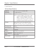
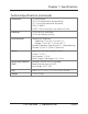
Chapter 1: Specifications 1. Specifications Technical Specifications Approvals FCC, TUV, CE, UL®, CSA, RoHS, WEEE Bandwidth 120 Mbps maximum Default IP Address 169.254.x.x (with no DHCP address) NOTE: T o find the IP address of any receiver, simply connect to monitor and power up to get IP address. To find the IP address of any other receiver or transmitter, use Telnet to connect to any device in the system and use a “node_list” command or connect with the serial interface.
Chapter 1: Specifications Technical Specifications (continued) Connectors (1) HDMI female, (1) RJ-45 interconnect/LAN connection, (1) 2.1-mm barrel connector for power, (2) RJ-12 6P6C† †NOTE: Only 4 center pins are used at this time. Indicators (1) LED for Link and Power; (1) LED for Network Activity Environmental Temperature Tolerance: Operating: 32 to 104° F (0 to 40° C); Storage: -4 to +140° F (-20 to +60° C) Humidity Tolerance: Operating: 80%, noncondensing; Altitude: 10,000 ft.
Chapter 2: Overview 2. Overview 2.1 Introduction The MediaCento IPX with PoE is a perfect solution for audio and video signal extension via an existing Local Area Network (LAN) system. With multicast technology, one local unit can drive multiple remote units with no extra network load. There are 16 selectable channels that can be used to transmit to multiple receivers.
Chapter 2: Overview • Provide automatic EDID configuration. • Use well-developed Ethernet technology and TCP/IP communication protocol. • Transmitters and Receivers are HDCP-compliant and Blu-ray ready. • HDTV compatible; support 1080p, 1080i, 720p, 720i. • Compatible with popular screen resolutions: XGA, SXGA, UXGA, WSXGA. 2.3.
Chapter 2: Overview • (1) DB9 F to RJ-11 adapter • (1) RJ-11 to RJ-11 cable VX-HDMI-POE-VRX also has: • (1) MediaCento IPX Video Wall Receiver 2.5 Additional Items You Will Need • HDCP-compliant monitors with HDMI interface for the HDCP video source • CAT5/5e/6 UTP cable (EIA/TIA 568B industry-standard compliant) • Layer 2 or 3 switches with IGMP and optional Power over Ethernet (PoE) 2.
Chapter 2: Overview 10 Figure 2-3. Transmitter top panel. 724-746-5500 | blackbox.
Chapter 2: Overview Table 2-1. Components of the Transmitters. Number Component Description 1 F2 button See Section 2.6.4. 2 F1 button See Section 2.6.4.
Chapter 2: Overview 2.6.2 Receivers 1 2 3 4 5 Figure 2-4. Receiver front panel. 6 7 8 9 Figure 2-5. Receiver back panel. 724-746-5500 | blackbox.
Chapter 2: Overview 10 Figure 2-6. Receiver top panel. Page 16 724-746-5500 | blackbox.
Chapter 2: Overview Table 2-2. Components of the Receivers. Number Component Description 1 F2 button See Section 2.6.4. 2 F1 button See Section 2.6.4.
Chapter 2: Overview 2.6.3 Indicators The LEDs on the extender units show the real-time status indicating the linking and communication between the Transmitter/Sender unit and the Receiver unit. Users can identify the current status through the LED indicators on the unit. The quality of the output signal will depend largely upon the quality of the video source, cable, and display device used. Low-quality cables degrade output signals, causing elevated noise levels.
Chapter 2: Overview Table 2-3. Function buttons (continued). Button Action Description 1. P ress and hold the F1 button. 2. A pply power to the unit. F1 3. R elease right after the Network Status LED starts blinking. Resets the box to factory defaults. 4. Power cycle the unit. 2.6.5 EDID Copy Copying the EDID will enable the receiver to send correct resolutions to your output. Although the default EDID will work in most cases, some monitors will not work with it.
Chapter 3: Installation 3. Installation WARNINGS: Make sure that all devices are powered off before connecting to the unit. Make sure all devices you will connect are properly grounded. Place cables away from fluorescent lights, air conditioners, and machines. NOTE: EDID copy is required for DVI monitors. System Requirements for PoE 1. Ensure that a PSE device supports PoE function. 2. Ensure that a PSE device can provide sufficient power on the Ethernet cable. 3. STP and FTP cabling are recommended.
Chapter 3: Installation RX RX RX TX Monitor DVD player TX Blu-ray TX PC Layer 2/3 switch with IGMP RX Monitor RX Monitor RX Monitor RX Monitor Figure 3-1. Installation diagram. 724-746-5500 | blackbox.
Chapter 4: Configuration 4. Configuration 4.1 Basic Configuration The rotary switch on each device decides the channel of the device when booting. For a receiver or receivers to connect to a transmitter, they must be on the same channel. Each transmitter should be on a separate switch setting and the receivers should be on the same switch setting as the desired transmitter. After you change the switch setting, you must reboot the device for the changes to take effect. 4.
Chapter 4: Configuration 4.2.1 Accessing through Serial 1. Using the client, select “serial” and enter “115200” for the speed (baud rate). Figure 4-1. PuTTY configuration screen using serial. 2. No username or password is required. Just press enter. 4.2.2 Accessing through Telnet 1. Using the client, enter in the IP address of the device. 2. Change the port to 24. 724-746-5500 | blackbox.
Chapter 4: Configuration Figure 4-2. PuTTY configuration screen using Telnet. 3. The default password is root. Page 24 724-746-5500 | blackbox.
Chapter 5: Advanced Commands 5. Advanced Commands These are advanced configurations and require knowledge of IP networking protocols and multicasting. Do not attempt to run any commands, modify files, or change any other settings apart from the specific configurations noted here. All commands are case-sensitive. To list names and IP information of all connected MediaCento IPX devices, type in: node_list Figure 5-1. Names and IP information list.
Chapter 5: Advanced Commands Figure 5-2. Current configured parameters list. To reset to factory default, setting the IP mode to autoip and removing any overrides, type in: reset_to_default.sh To change the baud rate of the serial extension interface, type in: stty X –F /dev/ttyS0 (replace X with desired baud rate) To disable/enable the link for a specific device, type in: ast_send_event -1 e_stop_link ast_send_event -1 e_reconnect 5.
Chapter 5: Advanced Commands 2. DHCP client gets an address from the local DHCP server. CAUTION: Make sure a DHCP client is connected or problems will occur. 3. S tatic allows you to manually change the IP address and netmask of the device. This requires further input before reboot.
Chapter 5: Advanced Commands Table 5-1. Channel listing for multicast address. Channel IDs Multicast Address 225.0. B0 B1 B2 B3 ID 0. 0 0 0 0 225.0. 1. 0 0 0 1 225.0. 0. 1 0 0 2 225.0. 1. 1 0 0 3 225.0. 0. 0 1 0 4 225.0. 1. 0 1 0 5 225.0. 0. 1 1 0 6 225.0. 1. 1 1 0 7 225.0. 0. 0 0 1 8 225.0. 1. 0 0 1 9 225.0. 0. 1 0 1 A 225.0. 1. 1 0 1 B 225.0. 0. 0 1 1 C 225.0. 1. 0 1 1 D 225.0. 0. 1 1 1 E 225.0. 1.
Chapter 5: Advanced Commands 5.2.1 Transmitter To change the multicast group IP, type in: astparam s multicast_ip 225.0.B0.B1B2B3 To change the hostname ID of the transmitter, type in: astparam s hostname_id B0B1B2B3 ast_send_event -1 e_chg_hostname To override DIP rotary switch setting on bootup: astparam s reset_ch_on_boot n (space between boot and the n) astparam save reboot 5.2.2 Receiver To change the multicast group IP, type in: astparam s multicast_ip 225.0.B0.
Chapter 5: Advanced Commands Figure 5-4. Options controlling local serial lines. For both transmitter and receiver units, the added RJ-11 to DB9 serial cable needs to be connected to the second serial port on the devices. 5.4 Telnet Extension Telnet serial extension allows for serial output from a receiver through a Telnet connection. This disables serial input coming from a transmitter but allows for 2-way communication to specific devices. NOTE: T elnet extension requires custom firmware.
Chapter 5: Advanced Commands To set up a Telnet extension: 1. Using a Telnet protocol, use Port 6752. Figure 5-5. Setting up Telnet extension using a Telnet protocol. 724-746-5500 | blackbox.
Chapter 5: Advanced Commands 2. Turn off line echo and local line editing. Figure 5-6. Turning off line echo and local line editing. Page 32 724-746-5500 | blackbox.
Chapter 6: Accessing the Web Interface 6. Accessing the Web Interface The Web interface can be used to view information about the device, upload a firmware file to the device, and for video wall transformers configuration. The Web interface will not give network information or screen previews. 6.1 Accessing the Transmitter without an IP Address You can access the transmitter directly with a serial connection, and find the IP address using the “node-list” command. See Chapter 5.
Chapter 6: Accessing the Web Interface Table 6-1. Rotary Switch position settings. Position Four-digit setting Position Four-digit setting 0 0000 8 0001 1 1000 9 1001 2 0100 A 0101 3 1100 B 1101 4 0010 C 0011 5 1010 D 1011 6 0110 E 0111 7 1110 F 1111 Figure 6-1. Setup screen (without IP address). Page 34 724-746-5500 | blackbox.
Chapter 6: Accessing the Web Interface 6.2 Accessing the Web Interface for a Transmitter or Receiver with an IP Address 1. C onfigure the control PC’s network setting as 169.254.xxx.xxx IP domain with netmask 255.255.0.0. Default gateway and DNS can be left blank. For Windows 7: http://windows.microsoft.com/en-us/windows7/change-tcp-ip-settings 2. Open a Web browser and insert the IP address of the device. Figure 6-2. Web setup screen (with IP address). 724-746-5500 | blackbox.
Chapter 7: Video Wall Features 7. Video Wall Features Using the Video Wall features, you can send video and audio to unlimited ouputs through IP. Format the video wall so that separate sections of the video can be sent to different outputs. Basic settiings allow for bezel compensation and different arrays of screens. Advanced settings allow for video manipulation to specific outputs.
Chapter 7: Video Wall Features Figure 7-2. Basic Setup screen. 724-746-5500 | blackbox.
Chapter 7: Video Wall Features Table 7-1. Basic Setup screen components. Component Description Bezel and Gap Compensation Dimensions of screen (inside and outside width and height). Wall Size and Position Layout Select number of vertical and/or horizontal monitors, row position, and column position. Apply To: “All” device(s) in the list Click on the “Apply” button to apply settings. Show OSD checkbox Check this box to output each receiver’s specific number to the connected monitor.
Chapter 7: Video Wall Features Figure 7-3 shows the Advanced Setup screen. Table 7-2 describes its components. Figure 7-3. Advanced Setup screen. 724-746-5500 | blackbox.
Chapter 7: Video Wall Features Table 7-2. Advanced Setup screen components. Component Description Step 1: Choose control target Click on the arrows and buttons to select a control target. Show OSD checkbox Check this box to output each receiver’s specific number to the connected monitor. Step 2: Control options Reset to Basic Setup, Single Host Mode checkbox Check this box, then press the “Reset” button.
Chapter 7: Video Wall Features Figure 7-4 shows the Advanced Commands screen. Table 7-3 describes its components. Figure 7-4. Advanced Commands screen. 724-746-5500 | blackbox.
Chapter 7: Video Wall Features Table 7-3. Advanced Commands screen components. Component Description Screen Layout (Row x Column) Select the number of rows and columns from the drop-down menu, then click on the “Apply” button. Row Position Select the row from the drop-down menu, then click on the “Apply” button. Column Position Select the column from the drop-down menu, then click on the “Apply” button.
Chapter 8: Troubleshooting 8. Troubleshooting 8.1 Problem/Solutions Problem: No video on monitor at bootup. Solutions: 1. Check the device power using the Link/Power LED. 2. Check the network connection using the Network LED. 3. Check the video connection using the Link/Power LED. 4. Make sure that the DIP rotary switch is set to the correct ID. NOTE: If manually changed, make sure the IDs match. 5. I f you’re using a mix of multicast and unicast units, make sure they match up correctly. 6.
Chapter 8: Troubleshooting • the components involved in the problem. • any particular application that, when used, appears to create the problem or make it worse. 8.3 Shipping and Packaging If you need to transport or ship your MediaCento IPX with PoE: • Package it carefully. We recommend that you use the original container. • If you are returning the unit, make sure you include everything you received with it.
Appendix: Connector Pinouts Appendix. Connector Pinouts Figure A-1 shows the DB9 to RJ-12 or RJ-11 connector pinouts. Figure A-1. DB9 to RJ-12 6P6C or RJ-11 (4P4C) cable pinout. 724-746-5500 | blackbox.
NOTES Page 46 724-746-5500 | blackbox.
NOTES 724-746-5500 | blackbox.
Chapter Black Box Tech Support: FREE! Live. 24/7. Tech support the way it should be. Great tech support is just 60 seconds away at 724-746-5500 or blackbox.com. About Black Box Black Box provides an extensive range of networking and infrastructure products. You’ll find everything from cabinets and racks and power and surge protection products to media converters and Ethernet switches all supported by free, live 24/7 Tech Support available in 60 seconds or less. © Copyright 2014. Black Box Corporation.