OCTOBER 1994 TS675A BRTS-100 ISDN Test Set A 1 8 PA US AT IL ST FA ST TE SS 1 E LIN ST TE 8 B M TO R S 7-8 W E PIN AUX AN PO PH RM NO V ER K RE EA TE SP INA M RM H TE 00 O 1 IVE CE RE -6dB L T VE MI LE ANS ITY ” 0 TR CTIV ED “ R E ” A 1” C “D RN “ DAN TY G E UI P IM TIN TE N A CO NITI E I LIN E AC TR ONE T 0 -10 et TS st S BR Te N ISD F OF ON R WE PO ON F OF CUSTOMER SUPPORT INFORMATION Order toll-free in the U.S.: Call 877-877-BBOX (outside U.S.
FCC STATEMENT FEDERAL COMMUNICATIONS COMMISSION AND INDUSTRY CANADA RADIO FREQUENCY INTERFERENCE STATEMENTS This equipment generates, uses, and can radiate radio-frequency energy, and if not installed and used properly, that is, in strict accordance with the manufacturer’s instructions, may cause interference to radio communication.
BRTS-100 ISDN TEST SET NORMAS OFICIALES MEXICANAS (NOM) ELECTRICAL SAFETY STATEMENT INSTRUCCIONES DE SEGURIDAD 1. Todas las instrucciones de seguridad y operación deberán ser leídas antes de que el aparato eléctrico sea operado. 2. Las instrucciones de seguridad y operación deberán ser guardadas para referencia futura. 3. Todas las advertencias en el aparato eléctrico y en sus instrucciones de operación deben ser respetadas. 4. Todas las instrucciones de operación y uso deben ser seguidas. 5.
NOM STATEMENT 12. Precaución debe ser tomada de tal manera que la tierra fisica y la polarización del equipo no sea eliminada. 13. Los cables de la fuente de poder deben ser guiados de tal manera que no sean pisados ni pellizcados por objetos colocados sobre o contra ellos, poniendo particular atención a los contactos y receptáculos donde salen del aparato. 14. El equipo eléctrico debe ser limpiado únicamente de acuerdo a las recomendaciones del fabricante. 15.
BRTS-100 ISDN TEST SET TRADEMARKS USED IN THIS MANUAL Any trademarks mentioned in this manual are acknowledged to be the property of the trademark owners.
CONTENTS Contents Chapter Page 1. Specifications .....................................................................................................2 2. Introduction .......................................................................................................3 2.1 Overview .......................................................................................................3 2.2 How to Use This Manual .............................................................................3 2.3 Features .
BRTS-100 ISDN TEST SET 1. Specifications Input/Output — (2) modular 8-pin jacks (included) ISDN Interface — S/T Line Type — ISDN BRI Nominal Data Rate — 192 kbps Power — 9-VDC battery Size — 7.3"H x 3.3"W x 1.1"D (18.5 x 8.3 x 2.8 cm) Weight — 11 oz. (311.
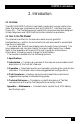
CHAPTER 2: Introduction 2. Introduction 2.1 Overview The BRTS-100 ISDN Test Set is a portable, hand-held, communication-line tester that helps you troubleshoot and verify ISDN S/T interface lines (see Figure 2-1). The Test Set supports a variety of comprehensive tests designed to help telephone and ISDN craft technicians isolate line problems. 2.
BRTS-100 ISDN TEST SET A 1 8 1 E LIN ST TE US AT IL ST FA ST TE SS PA 8 B -8 R S7 WE PIN AUX PO M TO AN PH M OR N R V KE RE EA TE SP INA M RM H TE 00 O 1 IVE CE RE 6dB L- T VE MI LE ANS ITY ” 0 TR CTIV ED “ R E ” A 1” C “D N “ AN Y GR ED UIT P IM TIN TE N A CO NITI E I LIN E AC TR ONE T 0 -10 et T S st S BR Te N ISD F OF ON ON R WE PO F OF Figure 2-1. The BRTS-100 ISDN Test Set. 2.
CHAPTER 3: Operation 3. Operation 3.1 Overview You can operate the BRTS-100 ISDN Test Set in a variety of modes. Select them by turning the selector dial on the left of the unit (see Figure 3-1). The indicator lights (LEDs) on top of the unit indicate test results. The various test modes and indicator lights are explained in more detail below. 3.2 Connecting the Unit In the shipping box, you’ll find: • The BRTS-100 ISDN Test Set. • (1) 9-volt battery. • An RJ-45-to-RJ-45 cable.
BRTS-100 ISDN TEST SET INDICATOR LEDS A 1 8 PA 1 US AT IL ST FA ST TE SS 8 B -8 R S7 WE PIN AUX PO M TO AN PH M OR F OF N R V KE RE EA TE SP INA M RM H TE 00 O 1 IVE CE RE -6dB L T VE MI LE ANS ITY ” 0 TR CTIV ED “ R E ” A 1” C “D N “ AN Y GR ED UIT P IM TIN TE N A CO NITI E I LIN E AC TR ONE T 0 -10 et T S st S BR Te N ISD ON ON R WE PO INDICATOR LED F OF 10 E LIN ST TE SPEAKER I/O PORTS A & B (8-PIN CONNECTORS) TEST MODE SELECT DIAL FEATURE BUTTONS Figure 3-1.
CHAPTER 3: Operation TO NT1 A TERMINAL 1 8 1 8 B BRTS-100 ISDN TEST UNIT PASSIVE BUS TO NT1 A 1 8 1 8 B BRTS-100 ISDN TEST UNIT POINT-TO-POINT Figure 3-2. Connecting the Test Set for point-to-point or passive-bus configurations.
BRTS-100 ISDN TEST SET To connect the Test Set in a point-to-point configuration, simply connect the 8-pin plug to either the A or B port located on top of the unit. To connect the Test Set in a passive bus configuration, connect the line from the NT1 to either the A or B port, and connect the termi-nal to the other port. The ports are parallel, so they can be used interchangeably (see Figure 3-2). 3.3 Powering Up the Unit Power up the Test Set up by depressing the POWER feature button (Figure 31).
CHAPTER 3: Operation NOTE: In reverse mode, the light indicators are opposite. AUXILIARY POWER LIGHT — Indicates the presence and polarity of auxiliary power. Green light — Auxiliary power present, normal polarity. Red light — Auxiliary power present, reverse polarity. No light — No auxiliary power present. TEST STATUS (PASS/FAIL) LIGHTS — Reflects test status. INITIATE LIGHT (yellow LED) — The INITIATE button and light are used in testing modes.
BRTS-100 ISDN TEST SET 4. Test Procedures 4.1 Overview This chapter gives you several suggested test procedures. However, it is by no means the only way to use the Test Set to isolate trouble or to verify lines. NOTE: The following procedures assume certain conditions exist (that procedures are followed in the correct order.) These conditions are described at the beginning of each procedure.
CHAPTER 4: Test Procedures NT1 TERMINAL UNDER TEST BRTS-100 UNIT Figure 4-2. Test Configuration 2. Test Configuration 2 — Passive Bus (Figure 4-2) To put the terminal in the Passive Bus Test Configuration: 1. Disconnect the terminal. NOTE: With a passive bus, the S/T interface may disrupt the operation of the other devices on the bus. 2. Connect the S/T jack to Port B of the Test Set. 3. Connect the terminal to Port A of the Test Set. 4.
BRTS-100 ISDN TEST SET 4.2 Comprehensive Troubleshooting Procedure This troubleshooting guide is for the user who is either installing a new line and wants to verify the S/T interface, or has a problem with an in-service ISDN terminal. It is a comprehensive procedure which uses virtually all of the Test Set’s testing capabilities and features. This Procedure uses other test procedures outlined in this section. If you identify a problem at any point in this procedure, stop the test and fix the problem.
CHAPTER 4: Test Procedures 12. Put the circuit into its normal operating configuration. (Connect all terminals to the S/T interface.) START Comprehensive Troubleshooting Flow Chart Initially, the Test Set should be in NORMAL mode PUT CIRCUIT IN POINT TO POINT CONFIGURATION (CONFIG.
BRTS-100 ISDN TEST SET 13. a. If the terminal works, there’s no need to proceed any further. b. If the terminal does not work, proceed to step 14. 14. Perform the PAIR REVERSAL test procedure (see page 22). 15. Put the circuit into its normal operating configuration. (Connect all terminals to the S/T interface.) 16. a. If the terminal works, there’s no need to proceed any further. b. If the terminal does not work, proceed to step 17. 17.
CHAPTER 4: Test Procedures 4.3 Check Power Some (not all) ISDN terminals require power from the S/T interface. This procedure verifies that power is received properly at the S/T interface. See Figure 4-5 for an outline of the functions performed in this test. 1. Put the circuit in Test Configuration 1. 2. Make sure the Test Set is in NORMal mode; LINE button should be out. 3.
BRTS-100 ISDN TEST SET CHECK POWER CHECK POWER If the terminal requires power from the line, this procedure will verify that power is being transmitted properly. Assumes the Test Set is in NORMAL mode. PUT CIRCUIT IN POINT TO POINT CONFIG. (CONFIG.
CHAPTER 4: Test Procedures With the Check Loop procedure, first check to see if the transmit pairs (pins 3 and 6) and the receive pairs (pins 4 and 5) are reversed. 1. Put the Test Set in REVerse mode; LINE button should be in. 2. Put circuit in the Point-to-Point NT1 Test Configuration (Test Configuration 1). 3. Put the Test Set in the LINE TEST test mode. 4. Press the INITIATE button. 5. a. If the Green Test Status light goes on, the Loop is reversed. b.
BRTS-100 ISDN TEST SET CHECK LOOP CHECK LOOP Assume 1. Power good 2. LINE TEST failed 3 Test Set is in NORMAL mode PUT CIRCUIT IN POINT TO POINT CONFIGURATION (CONFIG. 1) CHECK IF TX & RX PAIRS ARE TRANSPOSED SWITCH TO REVERSE, INITIATE LINE TEST LINE, LINE TEST INITIATE TX & RX PAIRS ARE TRANSPOSED GRN TEST STATUS? RED DONE SWITCH TO NORMAL LINE, RECEIVE A Figure 4-6.
CHAPTER 4: Test Procedures A RED TEST STATUS? SWITCH TO REVERSE, DO CONTINUITY TEST GRN PROBLEM WITH TX PAIR LINE CONTINUITY CONTINUITY OPEN IN RX PAIR TEST STATUS? GRN TEST STATUS? B GRN RED PUT BACK IN NORMAL MODE, PUT IN LEVEL TEST MODE OPEN IN TX PAIR LEVEL RED TEST STATUS? SIGNAL LEVEL TOO LOW GRN NT1 OR SWITCH NOT WORKING Figure 4-6. Check loop flow chart (2 of 3).
BRTS-100 ISDN TEST SET B CHECK FOR SHORT IN TRANSMIT PAIR PUT BACK IN NORMAL MODE, PUT IN IMPEDANCE TEST MODE LINE IMPEDANCE RED TEST STATUS? NT1 NOT TERMINATED OR SHORT ON TX PAIR GRN PROBLEM WITH NT1 Figure 4-6. Check loop flow chart (3 of 3).
CHAPTER 4: Test Procedures 10. Put the Test Set in the CONTINUITY Test Mode. 11. a. If the Green Test Status light goes on, there is a physical connection between the terminal and the NT1. b. If the Red Test Status light goes on, there is no continuity on the receive pair between the terminal and the NT1. You should check the loop for opens. There’s no need for any further testing. 12. The problem may be that the signal received at the NT1 is too low.
BRTS-100 ISDN TEST SET 4.5 Passive Bus—Check Terminations When you’re using a passive-bus configuration, it’s imperative that the last device on the bus be terminated at 100 ohms. The other devices on the bus must be left unterminated. Termination should be an option on each ISDN terminal. Refer to your terminal’s user manual to determine how to configure the terminal in terminated/unterminated mode. See Figure 4-7 for an outline of the functions performed in this test.
CHAPTER 4: Test Procedures 1. Determine which devices are the first and last devices on the bus. The first device is the one closest to the NT1. The last device is the one furthest from the NT1. See Figure 4-8 for an example of proper device termination. 2. Go to the first device on the bus. 3. Put the Test Set in TERMINATED and NORMAL mode. 4. Put circuit in Test Configuration 3. 5. Make sure the Test Set is in REVerse mode; LINE button should be in. 6. Power down the terminal. 7.
BRTS-100 ISDN TEST SET NT1 FIRST DEVICE TERMINAL TERMINAL NOT TERMINATED NOT TERMINATED TERMINAL TERMINAL NOT TERMINATED NOT TERMINATED TERMINAL NOT TERMINATED TERMINAL NOT TERMINATED TERMINAL NOT TERMINATED TERMINAL LAST DEVICE SHOULD BE TERMINATED AT 100 OHMS Figure 4-8. Proper device terminations diagram.
CHAPTER 4: Test Procedures 4.6 Pair Reversal When you use the passive-bus configuration, it’s imperative that all the transmit pairs (from terminal) be wired the same. That is to say, pins 3 and 6 from each terminal on the bus must be wired to pins 3 and 6 of the NT1 respectively. On a point-to-point configuration, the circuit will operate properly even if the pair is reversed (pin 3 [terminal] to pin 6 [NT1], pin 6 [terminal] to pin 3 [NT1]).
BRTS-100 ISDN TEST SET b. If the Red Test Status light goes on, the terminals’ wires are crossed— pin 3 of terminal is electrically connected to pin 6 of the other terminal. At this point, you should check the wiring of both terminal A and terminal B. 10. Repeat steps five through eight until all ports on the bus have been checked. Assume LINE TEST passe independently on every port.
CHAPTER 4: Test Procedures A NEED TO CHECK ALL PORTS ON THE BUS GO TO NEXT OUTLET ON BUS PUT 2nd BRTS-100 (B) ON BUS, TERMINATED TERMINATE, TRANSMIT, INITIATE GRN RED TEST STATUS? WIRING THE SAME ON PORT UNDER TEST AND PORT BRTS-100 (A) IS ON WIRING DIFFERENT ON PORT UNDER TEST AND PORT BRTS-100 (A) IS ON CHECK WIRING, PINS 3 & 6 UNPLUG 2nd BRTS-100 (B) NO ALL PORTS CHECKED? YES ALL PAIR REVERSALS IDENTIFIED Figure 4-9. Pair reversal flow chart (2 of 2).
BRTS-100 ISDN TEST SET NT1 TERMINAL “A” BRTS-100 UNIT TERMINAL “B” BRTS-100 UNIT MOVE BRTS-100 “B” TO EVERY PORT Figure 4-10. Pair reversal diagram.
CHAPTER 4: Test Procedures 4.7 Monitor Use this test when you’ve determined there’s nothing physically wrong with the circuit. The MONITOR procedure checks for any D channel activity. See the Monitor Flow Chart in Figure 4-11 for an outline of the functions performed during this test. Before using this procedure, the following prerequisites must be met: 1. All terminals are properly terminated (CHECK TERMINATIONS). 2. No pair reversals exist on a passive bus (PAIR REVERSAL). 3. LINE TEST passes. 4.
BRTS-100 ISDN TEST SET Monitor Assumes MONITOR ASSUMES 1. Test Set is in Normal Mode 1. BRTS-100 is in normal mode. are Properly 2. All Terminals Terminated 2. All terminals are properly terminated. 3. No Pair Reversals on Passive Bus 3. No pairPasses reversals 4. LINE TEST on passive bus. 5. Terminal Does Not Work 4. LINEReceiving TEST passes. 6. Terminal Proper Power 5. Terminal does not work. 6. Terminal receiving proper power.
CHAPTER 5: Technical Reference 5. Technical Reference 5.1 Power-Source Indicators The Phantom Feed light indicates the presence and polarity of battery power. In NORMal mode, the Test Set verifies that the terminal’s transmit pairs are positive and its receive pairs are negative. In REVerse mode, the Test Set verifies that the opposite (transmit negative and receive positive) is true. See Figure 5-1.
BRTS-100 ISDN TEST SET 5.2 Activation/Deactivation Modes The following information provides the steps that lead to an Active Link state and subsequent Activation/Deactivation modes (Figure 5-2) between the Test Set (TE) and an NT device. The Test Set uses this Activation/Deactivation procedure in Line Test, Transmit, and D Activity modes. See Figure 5-3 for a diagram of Info 0–Info 4. DIU—Deactivate Indication (Timer [32 ms] expired or Info 0 received [during 16 ms] after deactivation request).
CHAPTER 5: Technical Reference CCITT I.430 Info 0: No Signal 48 bits in 250 microseconds TE to NT D L F B1B1B1B1B1B1B1B1 L D L F L B2B2B2B2B2B2B2B2 L D L B1B1B1B1B1B1B1B1 L D L B2B2B2B2B2B2B2B2 L D L F L CCITT I.430 Info 1: 48 bits in 250 microseconds NT to TE D L F L B1B1B1B1B1B1B1B1 E D A F N B2B2B2B2B2B2B2B2 E D S1B1B1B1B1B1B1B1B1 E D S2B2B2B2B2B2B2B2B2 E D L F L CCITT I.
BRTS-100 ISDN TEST SET REC. ECHO BITS=? TRANS. BRTS-100 NT1 TRANS. REC. D=01010101... D=E, LINE IS GOOD, PASS D≠E, LINE IS BAD, FAIL Figure 5-4. Transmit and line test. D Activity (See Figure 5-5) The D Activity test is designed to run when the Test Set is bridged onto the S/T interface with an ISDN terminal. D Activity will monitor the Echo bits for any D channel data transmitted by the terminal. The D Activity test is conducted as follows: 1.
CHAPTER 5: Technical Reference CCITT 1.430 2.5K OHMS 250 2KHz 20KHz 30KHz 1MHz FREQUENCY NT & TE IMPEDANCE TEMPLATE FROM 0 - 30 KHz Figure 5-6. CCITT 1.430. 5.3 AC Impedance As shown in Figure 5-6, CCITT recommends that the AC impedance at 20 to 30 KHz should be greater than 2.5K ohms. To detect this, the Test Set puts an R-sense resistor in series with the device under test (Figure 5-7). A 21- KHz sinusoidal voltage, approximately 1V peak-to-peak, is generated.
BRTS-100 ISDN TEST SET AC IMPEDANCE + DEVICE UNDER TEST - 21KHz GEN ~ 1vpp TA/NT 100Ω 3 ISPC I.C. 6 STATUS HIGH DETECT INDICATORS APPROX. 150 OHMS SAMPLE & HOLD SW1 FILTER PRE AMP WINDOW COMPARATOR R-SENSE 100Ω Figure 5-7. AC impedance. VDD 9V BATTERY LOOP DETECT LOOP RESISTANCE 0 - APPROX. 5KΩ MAX. AMOUNT 5mA 3 6 100Ω BRTS-100 Figure 5-8. DC continuity.
CHAPTER 5: Technical Reference 5.5 Speaker The incoming frequency to the speaker is divided by eight. Since ISDN signals are transmitted at 96 KHz, it has to be reduced in order to be heard over the speaker. When the Test Set is in TRACE TONE mode, the incoming frequency to the speaker is divided by four. So a TRACE tone received by the Test Set will be heard at 1 KHz. See Figure 5-9. BRTS-100 BRTS-100 REC. 4KHz TRANS. TRANS. 4KHz REC. ÷4 1KHz 1KHz ÷4 Figure 5-9.
BRTS-100 ISDN TEST SET Appendix: Maintenance The Test Set requires very little maintenance other than replacing the 9-VDC battery periodically and possibly replacing one or both of the two 8-pin RJ-45type jack connectors. NOTE: Average battery life is approximately 15 hours of continuous use. Battery Replacement To replace the 9-VDC battery follow these steps and refer to Figure A-1. 1. Using a #2 Phillips screwdriver, remove the battery cover retaining screw. 2.
APPENDIX: Maintenance 8-Pin Jack Replacement These connectors need to be replaced only when connections no longer permit a secure-tight connection or when connectors are damaged. In standard use, however, these connectors shouldn’t ever need to be replaced. Follow these steps and see Figure A-2. 1. Remove the five screws from the Test Set back cover. 2. Gently lift off the back cover to expose the inside of the unit. Remove the damaged connector(s) as indicated in Figure A-2. 3.
© Copyright 2002. Black Box Corporation. All rights reserved.