
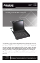
user manual


Page 3
ServView IV
(Only the specifications, descriptions, and instructions for the ServView product
code listed for your ServView IV model on the front of this sheet will apply.)
• Ten 10/32” rackmounting screws and cage nuts. (Eight are required for
assembly, two are extra.)
NOTE: The components that come with your ServView IV might vary and are
subject to change without notice.
To mount the ServView IV in a 19” rack, take these steps:
1. Mount your CPU(s) and SUN servers in the rack where your ServView IV will
be installed.
2. Remove the backing plate that’s attached to the rear of the ServView IV by a
pair of screws.
3. Unscrew the retention screws that hold the KVM tray shut against the front
of the ServView IV.
CAUTION: We recommend that two people work together to perform step 4.
4. Tilt the ServView IV far enough sideways to get past the Cabinet’s rails, then
maneuver it through the Cabinet until its front and rear “mounting ears”
are even with the Cabinet’s front and rear rails. Straighten the ServView IV
back to level so that its front ears are flush against the front of the Cabinet’s
front rails and its rear ears are flush against the back of the Cabinet’s rear
rails. Align the upper and lower holes in the mounting ears (two in each ear
—eight all together—not including the middle hole in the front ears that’s
designed for the retention screws) with an appropriate set of holes in the
Cabinet’s rails, then secure the ServView IV to the rails using the included
screws.
5. Locate the keyboard, mouse, and video cables that come out of the back
of the ServView IV tray. Attach the connectors of these cables to the
matching connectors on your Sun server, computer CPU, or (if your ServView
IV includes an integrated ServSwitch) on the included User Cable that you’ll
then plug into one of the ServSwitch’s user ports.
6. Models with an integrated ServSwitch only: Plug the User Cable into one of
the ServSwitch’s user ports. Follow the directions in the ServSwitch manual
for attaching CPUs to the switch. Run the included power cord from the
ServSwitch’s power inlet to a working AC outlet.
7. Run the included power cord from the ServView IV’s power inlet to a working
AC outlet. Turn on the ServView IV. Refer to the manual for the ServView IV’s
components for information about configuring and operating them. (Note:
power must be first applied to the ServSwitch, then the CPU’s)
8. Plug in and power up the CPU(s) attached to your ServView IV.