ET0010A ET0100A ET1000A EncrypTight Enforcement Point (ETEP) Installation Guide EncrypTight acts as a transparent overlay that BLACK BOX integrates easily into any existing network architecture, providing encryption rules and keys to EncrypTight Enforcement Points. ® EncrypTight consists of a suite of tools that performs various tasks of appliance and policy management, including Policy Manager (PM), Key Management System (KMS), and EncrypTight Enforcement Points (ETEPs).
Table of Contents About This Document................................................................................................................. 7 Contacting Black Box Technical Support ............................................................................................... 7 Chapter 1: Product Overview..................................................................................................... 9 ETEP Introduction ........................................................................
Table of Contents Connecting the Cables: ET1000A .................................................................................................42 Powering on the ET1000A............................................................................................................. 43 Shutting Down the ETEP ..................................................................................................................... 45 Chapter 3: Initial Setup.........................................................
Table of Contents ET0100A Cabling .................................................................................................................... 68 ET1000A Regulatory Information .................................................................................................. 68 Safety ...................................................................................................................................... 68 EMI/EMC........................................................................
Table of Contents 6 ETEP Installation Guide
About This Document Purpose The ET VSE-series Installation Guide describes how to cable and install the Black Box™ ETEP EncrypTight Enforcement Points. Intended audience This document is intended for use by network technicians and security administrators who are familiar with setting up and maintaining network equipment. Assumptions This document assumes that its readers have an understanding of the following: ● Basic principles of TCP/IP networking, including IP addressing, switching and routing.
About This Document 8 ETEP Installation Guide
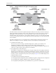
1 Product Overview This section includes the following topics: ● ETEP Introduction ● ET0010A Physical Description ● ET0100A Physical Description ● ET1000A Physical Description ● Features ● Specifications ETEP Introduction The EncrypTight Enforcement Point (ETEP) Variable Speed Encryptors (VSEs) are purpose-built encryption appliances that provide multi-layer data protection.
Product Overview Figure 1 Multipoint Ethernet Encryption using EncrypTight The ETEP interfaces with network equipment through two data ports, the local port and the remote port. Unencrypted traffic that originates from a trusted, local network is received on the local port, where the ETEP applies security processing to it. The encrypted traffic is then sent from the remote port to an untrusted network such as the Internet. At the opposite endpoint the process is reversed.
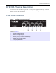
ET0010A Physical Description ET0010A Physical Description The ET0010A is a rack-mountable encryptor that can run at speeds ranging from 3-50 Mbps. It has three data ports on the front panel labeled Remote, Local, and Aux1. The following sections describe the ET0010A connectors and LED indicators. Front Panel Connectors The ET0010A front panel connectors are shown in Figure 2.
Product Overview Status Indicators The ET0010A status indictors are shown in Figure 3. The status indications are described in Table 1. Figure 3 ET0010A Status Indicators Elements of Figure 3: 1) Power LED 2) Alarm LED 3) Status indicators 4) Link indicators The following table describes how to interpret the ET0010A status indicators. Table 1 ET0010A Status Indicators Indicator Light State Indication Power (green) Off Unit is powered off. On Unit is powered on.
ET0100A Physical Description Rear Panel The ET0010A rear panel and external power supply are shown in Figure 4. Figure 4 ET0010A Rear Panel and External Power Supply Elements of Figure 4: 1) External power supply power connector 2) Rear panel power connector ET0100A Physical Description The ET0100A is a rack-mountable encryptor that can run at speeds ranging from 100–250 Mbps. The following sections describe the connectors and LED indicators that appear on the front and rear panels of the ET0100A.
Product Overview Front Panel Connectors The ET0100A front panel connectors are shown in Figure 5. Figure 5 ET0100A Front Panel Connectors Elements of Figure 5: 1) 10/100 Ethernet management port 2) RS-232 port 3) Remote port (encrypted traffic) 4) Local port (clear traffic) LED Indicators The ET0100A LED indictors are shown in Figure 6. The LED indications are described in Table 2.
ET0100A Physical Description The following table describes how to interpret the LEDs on the ET0100A front panel. Table 2 ET0100A Front Panel LED Indicators Indicator Light State Indication Power (green) Off Unit is powered off. On Unit is powered on. Off Loss of signal on the 10/100 link. On The link is up but no traffic is passing over the link. Blinking Indicates the presence of traffic on the 10/100 link. Off Loss of signal on the Gigabit link.
Product Overview ET1000A Physical Description The ET1000A is a rack-mountable 1 Gbps encryptor with dual power supplies. It can operate at speeds ranging from 500 Mbps–1 Gbps. The following sections describe the ET1000A connectors and LED indicators. Front Panel Connectors The ET1000A front panel connectors are shown in Figure 8.
ET1000A Physical Description Figure 9 ET1000A LED Indicators Elements of Figure 9: 1) Power LED 2) Alarm LED 3) Diagnostic display 4) Link indicators: 10/100 Ethernet management port 5) Link indicators: Gigabit management port 6) Link indicators: Aux1, Remote and Local ports 7) Power supply status LEDs Table 3 describes how to interpret the LEDs on the ET1000A front panel.
Product Overview Rear Panel The ET1000A rear panel is shown in Figure 10. Figure 10 ET1000A Rear Panel Elements of Figure 10: Power Supply # 2 1) Release lever for power supply 2 2) Power supply 2 receptacle 3) Power cord clip for power supply 2 4) Status LED for power supply 2. Green indicates normal operation. Red indicates a power fail state. Power Supply # 1 18 5) Power cord clip for power supply 1 6) Status LED for power supply 1. Green indicates normal operation.
Features Features ETEPs share many of the same features and capabilities across hardware models, as shown in Table 5. Hardware differences between the ETEP models are summarized in Table 4.
Product Overview Table 5 ETEP Feature Summary Category Feature Network Support • Ethernet • VLAN tag preservation • MPLS tag preservation • Jumbo frame support (ET0100A, CEP100-XSA, CEP1000, ET1000A) • Link state pass-through • IPv4 • IPv6 (Layer 2 Ethernet encryption mode) • NTP • Host or gateway packet reassembly option • Source or destination IP address • Source or destination port number • Protocol ID (Layer 3 IP packet and Layer 4 payload options) • VLAN ID (Layer 2 encry
Specifications Table 6 ET0010A Mechanical and Environmental Specifications Category Specification ET0010A Electrical/Mechanical Dimensions 19 inch rack mount design 1u tamper evident chassis Dimensions: 1.6” H x 8.0” W x 5.8” D Weight (without external power supply),1 pound 4 ounces External power supply: • Weight: 11 ounces • Input voltage: 100-240 VAC @ 1.5 amps, 50/60 Hz, autosensing • Output voltage: 12 VDC @ 5 amps Nominal input current: 0.
Product Overview Table 8 ET1000A Mechanical and Environmental Specifications Category Specification Interfaces (2) Gigabit Ethernet ports for encrypting and decrypting traffic (single mode, multimode, or copper) 10/100 Mbps auto-sensing Ethernet LAN port for management RS-232C port for management (1) Auxiliary Gigabit port for data traffic (not enabled) (1) Gigabit Ethernet port for management (not enabled) ET1000A Electrical/Mechanical Dimensions 19 inch rack mount design 1U tamper evident chassis
2 Installation This section includes the following topics: ● Before You Start ● Installing the ET0010A ● Installing the ET0100A ● Installing the ET1000A ● Shutting Down the ETEP Before You Start Before you prepare the ETEP for installation, review the following information: ● “Safety Guidelines” on page 23 ● “Software Requirements” on page 24 ● “ETEP Site Preparation” on page 25 ● “Firewall Ports” on page 26 Safety Guidelines The ETEP does not contain any field-replaceable internal parts
Installation WARNING The ETEP contains a lithium battery, which users should not attempt to replace. Battery replacement must be performed by qualified Black Box personnel. Risk of explosion if battery is replaced by an incorrect type. Used batteries should be disposed of according to the manufacturer’s instructions. CAUTION Electrostatic discharge (ESD) can damage electronic components and equipment.
Before You Start ETEP Site Preparation Most ETEP models can be mounted in a standard 19-inch rack using the supplied mounting kit, or simply placed on a rack shelf or solid surface. Before installing the ETEP in a 19-inch rack, consider the following guidelines: ● Ambient temperature Install the ETEP in an environment compatible with the 40ºC maximum recommended ambient temperature.
Installation Firewall Ports Table 10 lists the protocols that are used by the ETEPs and the EncrypTight system. Make sure that any firewalls in your system are configured to allow for the protocols that are required for your deployment: standalone ETEPs used for point-to-point encryption or ETEPs used in an EncrypTight system. Table 10 Firewall ports Standalone ETEPs CipherEngine Used for upgrading the software on the ETEP and retrieving appliance log files.
Installing the ET0010A The steps to perform for a typical installation are listed below. Table 11 Installation Steps Step Action to Perform Description 1 Review the cabling requirements. on page 27 2 Unpack the shipping package. on page 27 3 Install the ETEP in a rack or on a solid surface. on page 28 4 Connect the cables. on page 33 5 Apply power to the ETEP. on page 34 Cabling Requirements: ET0010A Table 12 outlines the standard cables used with each port on the ETEP.
Installation ● (1) Shielded null modem cable with an RJ-45 connector at one end and a DB-9 female connector at the opposite end. ● (1) Unshielded Category 5 straight through cable (UTP) with RJ-45 connectors ● Rack mount kit includes 2 mounting brackets, 4 large screws (#10-32), and 4 small black screws. The kit also includes 4 rubber feet and 4 small silver-toned screws with built-in washers for solid surface installations (see Figure 11).
Installing the ET0010A ● External power supply ● Two mounting brackets, supplied in the Accessory Kit ● (4) small black screws and (4) large #10-32 screws, supplied in the Accessory Kit ● #1 Phillips and #2 Phillips screwdrivers (user-supplied) To install the ETEP in a rack: 1 Place the unit on a solid surface, with the bottom panel facing up. When looking at the ET0010A from the bottom rear, the bracket that holds the power supply is on the right, as shown in Figure 12.
Installation Figure 13 Attach mounting brackets to the bottom panel. ET0010A is shown below. 3 Turn the ETEP face up and locate the external power supply. With the label side facing down, place the power supply in the mounting bracket cradle and snap it into place, as shown in Figure 14. Figure 14 Power supply installed in mounting bracket cradle on the ET0010A 4 Connect the power supply cable to the rear panel connector. Figure 15 shows the ET0010A power connector.
Installing the ET0010A Figure 15 Insert the power supply cable into the connector on the rear panel 5 Attach the mounting brackets to the rack’s front supports with the large #10-32 screws (item 1 in Figure 11), using a #2 Phillips screwdriver. Insert two screws in each bracket, using the top and bottom holes.
Installation Figure 17 Screw holes for rubber feet installation on bottom of unit 3 Place one of the rubber feet over the hole and insert a screw into the opening (Figure 18). Tighten the screw. Figure 18 Rubber feet installed 4 Repeat step 3 for the remaining feet. 5 Turn the unit over so that it is resting on the rubber feet. 6 Attach the external power supply to the power connector on the rear panel. Figure 19 shows the ET0010A rear panel and power supply.
Installing the ET0010A Figure 19 ET0010A rear panel connector for external power supply. Connecting the Cables: ET0010A Follow the instructions below to connect the ET0010A to the appropriate network devices (see Figure 20). To cable the ET0010A: 1 For initial setup, connect the RS-232 serial port directly to a PC or workstation. Using the null modem cable supplied by Black Box, insert the RJ-45 connector in the RS-232 port and connect the DB-9 female connector to your PC.
Installation Figure 20 ET0010A Cabling NOTE The Aux1 port on the ET0010A is not enabled in this release. Powering On the ET0010A Use the following procedure to power up the ETEP.
Installing the ET0100A To power on the ETEP: 1 Check that the power supply cable is properly inserted in the power connector on the ETEP rear panel. The ET0010A is shown in Figure 21. 2 Plug the power cord into the ETEP power supply. Attach the opposite end to a power source to apply power to the appliance. When the appliance powers up, all LEDs illuminate. The power LED remains lit until the unit is powered off.
Installation connector type required for the other end of the cable. Some cables are supplied by Black Box and others are user-supplied. Table 14 ET0100A Standard Cables ET0100A Port Cabling Supplied by...
Installing the ET0100A To mount the ETEP in a standard 19-inch equipment rack, have the following tools and materials available: ● Two mounting brackets, supplied in the Accessory Kit ● (6) small screws and (4) large screws, supplied in the Accessory Kit ● #1 Phillips and #2 Phillips screwdrivers (user-supplied) To install the ETEP in a rack: 1 Attach a mounting bracket to each side of the ETEP (near the front panel).
Installation Figure 23 ET0100A Cabling Powering on the ET0100A Use the following procedure to power up the ET0100A. To power on the ET0100A: ● On the appliance’s rear panel, plug the power cord into the ET0100A power receptacle. Attach the opposite end to a power source to apply power to the appliance. Due to the shielding in the power cable, you must exert significant pressure to properly insert the power cord into the ET0100A power receptacle.
Installing the ET1000A Figure 25 Improperly seated ET0100A power cable When the appliance powers up, all LEDs illuminate (see Figure 26). The Alarm LED illuminates briefly and the diagnostic code LED displays 88 to verify that the diagnostic display segments are functioning. The power LED remains lit until the unit is powered off.
Installation The steps to perform for a typical installation are listed below. Table 15 ET1000A Installation Steps Step Action to Perform Description 1 Review the cabling requirements. on page 40 1 Unpack the shipping package. on page 41 2 Prepare a space for installation of the ET1000A. on page 41 3 Connect the cables. on page 42 4 Apply power to the ET1000A. on page 43 Cabling Requirements: ET1000A Table 16 outlines the standard cables used with each port on the ET1000A.
Installing the ET1000A NOTE To meet the requirements of FCC Part 15 and the EU EMC Directive 2004/108/EC, use only shielded Category 5 cables with the ET1000A Ethernet management port. Unpacking the Shipping Carton: ET1000A Remove all product components from the shipping carton and compare the contents to the packing list. Keep all packaging in case it is necessary to return the unit. The ET1000A is packaged with the standard items listed below.
Installation To install the ET1000A in a rack: 1 Place the unit on a solid surface, with the top facing up. Position the mounting brackets on each side of the appliance, as shown in Figure 27. Figure 27 Mounting bracket orientation 2 Attach the mounting brackets to each side of the unit using the 8 small black screws provided in the accessory kit, and a #1 Phillips screwdriver, as shown in Figure 28.
Installing the ET1000A To cable the ET1000A: 1 For initial setup, connect the RS-232 port directly to a PC or workstation using a DB-9 null modem cable. This cable can be removed after initial setup is complete. 2 Connect the Ethernet management port to a LAN using a Category 5 shielded twisted pair (STP) cable with an RJ-45 connector. 3 Plug an SFP Gigabit transceiver into the ET1000A remote port.
Installation Figure 31 Dual power supplies on the ET1000A rear panel Elements of Figure 31: 1) Power cord clips 2) Status LED for power supply 2 3) Power receptacle for power supply 2 4) Power receptacle for power supply 1 5) Status LED for power supply 1 To power on the ET1000A: 1 On the appliance’s rear panel, plug the power cords into the power receptacles for each power supply. 2 Attach the opposite end of the first power cord to a power source.
Shutting Down the ETEP When the appliance powers up, all of the front panel LEDs illuminate (see Figure 33). The Alarm LED illuminates briefly and the diagnostic code LED displays 88 to verify that the diagnostic display segments are functioning. The power LED remains lit until the unit is powered off. The Power Supply LEDs illuminate for each operational power supply.
Installation You can perform a shutdown using a CLI command or ETEMS. The following procedure describes the CLI command. To shut down the ETEP from the CLI: 1 Log in as Administrator (user name admin) or Ops (user name ops). 2 At the command prompt, type shutdown. After the system shutdown is complete, the following message is displayed on the terminal. Power cycle required to reboot appliance 3 Unplug the power cable from the back of the unit or from the power outlet.
3 Initial Setup This section includes the following topics: ● Overview ● Logging In Through a Serial Link ● Configuring the Management Port ● Setting the Date and Time ● Entering a Throughput License ● Configuration Example ● Managing the ETEP Overview The following steps are required for initial setup of the ETEP: 1 Log in through a serial link. 2 Configure the management port. 3 Set the date and time. 4 Enter the throughput license.
Initial Setup To log in to the CLI via a serial link: 1 Connect the RS-232 serial port directly to a PC or workstation, as described in Chapter 2. 2 Open a terminal session through a VT-100 terminal emulation program such as HyperTerminal. Enter the connection name, the appropriate serial port (usually COM1 or COM2), and the following serial port parameters: Baud Speed 38,400 Parity None Data Bits 8 Stop Bits 1 Flow Control None 3 In the terminal session window, press ENTER.
Configuring the Management Port The Ethernet management port IP address identifies the ETEP to the management workstation. The subnet mask is the portion of the IP address that identifies the network or subnetwork for routing purposes. When the ETEP management port and the management workstation are on different subnets, the ETEP uses a default gateway to route packets to the other devices. The default gateway identifies the local router port that is on the same subnet as the ETEP Ethernet management port.
Initial Setup Table 18 Link speeds on the management port Auto-negotiate Auto-negotiate Fixed Speed Link speed ET0010A ET0100A, ET1000A All ETEPs 1000 Mbps Full-duplex 3 3 1000 Mbps Half-duplex To configure the management port: 1 At the command prompt, type configure to enter configuration mode. 2 At the config> prompt, type management-interface. 3 Assigning an IPv4 address to the management port is mandatory.
Setting the Date and Time Table 19 Management port autoneg command description Attribute Description enable Enables auto-negotiation on the management port. This is the default setting. disable Disables auto-negotiation on the management port. Use this setting to manually configure link speed and flow control. speed [100m-full | 10m-full | 100m-half | 10m-half] When auto-negotiation is disabled, the speed attribute specifies the link speed and duplex setting. The speed defaults to 100m-full.
Initial Setup the local time relative to UTC, add or subtract the offset hours from UTC for the local time zone (UTC ± n). The following examples give the local time at various locations at 12:00 UTC when daylight saving time is not in effect: ● New York City, United States: UTC-5; 07:00 ● New Delhi, India: UTC+5:30; 17:30 To set the date and time: 1 At the command prompt, type configure to enter configuration mode.
Configuration Example You need to install a license on each ETEP that you use. Licenses are linked to the serial number of the ETEP on which they are installed. You cannot install a license intended for one ETEP on a different ETEP. If you upgrade from a command line-only installation to a full EncrypTight deployment, you can no longer use the command line-only license and must acquire an EncrypTight license.
Initial Setup includes tools for appliance configuration, policy definition and deployment, and key generation and distribution. To prepare the ETEP for operation in the network, you will need to perform the following tasks: 1 Assign passwords 2 Configure the ETEP 3 Define security policies If you plan to operate the ETEP in FIPS mode, we recommend enabling FIPS mode as your first configuration task. Entering FIPS mode resets many configuration items, such as passwords, policies, and certificates.
4 Maintenance This section includes the following topics: ● Preventative Maintenance ● What To Do If an Appliance Fails ● Tamper Switch and Zeroization ● Cable Pinouts Preventative Maintenance Periodically perform maintenance on your ETEP. Keep components free of dust and other particulate matter. Examine cables for damage and ensure that airflow requirements have been met. On ETEP models that have fans, check the fans for reduced airflow caused by dust build-up and clean as necessary.
Maintenance What To Do If an Appliance Fails Most ETEP models do not contain any field-replaceable parts. If you experience an appliance failure, contact Customer Support for a replacement ETEP and throughput license. The ET1000A has field-replaceable power supplies. Contact Customer Support to obtain a replacement power supply in the event of a failure. See “Replacing the ET1000A Power Supply” on page 56 for removal and installation instructions.
What To Do If an Appliance Fails Figure 35 Power cord is removed from power supply # 2 3 Locate the release lever on the left of the power supply (Figure 36). Press the release lever inward toward the metal support to release the power supply latch. Pull the power supply outward to remove it from the chassis. Figure 36 Release lever on power supply # 2 4 On the replacement power supply, press the release lever toward the metal support and insert the new power supply until it latches (Figure 37).
Maintenance Figure 37 Slide the replacement power supply into the slot on the rear panel 5 Insert the power cord in the replacement power supply and secure it with the clip. 6 Reconnect power supplies 1 and 2 to their respective power sources. 7 Return the failed power supply to Black Box as directed by Customer Support. Tamper Switch and Zeroization The following ETEP models include a tamper switch: ET0010A, ET0100A, and ET1000A.
Cable Pinouts To recover the ETEP following zeroization: Wait approximately 20 minutes for the zeroization process to complete. If you are connected to the ETEP through the serial port, you will see the following message: Power cycle required to reboot appliance After cycling the power, you will be able to configure and manage the ETEP from its factory default settings.
Maintenance RS-232 Serial Cable: ET0100A/ET1000A The RS-232 serial cable on the ET0100A and ET1000A is a null modem cable with DB-9 connectors (female to male).
5 Troubleshooting This section includes the following topics: ● Symptoms and Solutions ● Diagnostic Code Display Symptoms and Solutions The following tables provide some solutions to common problems that may occur with your ETEP. LED Indicators Table 23 LED Indicators Symptom Explanation and Possible Solution No power light. • Make sure the power cable is attached and plugged in to both the device and the power outlet. Alarm light is lit. • The ETEP is in an error state.
Troubleshooting Table 23 LED Indicators Symptom Explanation and Possible Solution Power supply LED is off The power supply is unplugged or is unable to recover from a power interruption. • Make sure the power cable is attached and plugged in to the power supply and the power outlet. • Check the status LED on the power supply on the rear of the unit. If the LED is off, the power supply is not receiving power. If the LED is red, the power supply requires a manual power cycle.
Diagnostic Code Display If the ETEP is discarding traffic, check the system log for temperature warning notices to confirm that a temperature error occurred. Reboot the ETEP to resume normal operation. Diagnostic Code Display ETEPs display self-test codes during boot up, in addition to operational status and error conditions.
Troubleshooting Diagnostic Codes: ET0100A and ET1000A The 7-segment diagnostic display on the front panel of the following models displays self-test codes during boot up: ET0100A and ET1000A. After the ETEP boots, the display reflects the operational state of the appliance and error conditions. When the appliance powers up, all LEDs illuminate. The Alarm LED illuminates briefly and the diagnostic code LED displays 88 to verify that the diagnostic display segments are functioning.
Appendix A Environmental and Regulatory Information This section includes the following topics: ● WEEE Directive ● RoHS Directive ● Regulatory Information WEEE Directive Black Box is committed to environmentally responsible behavior. As part of this commitment, we have put in place a product end-of-life management solution that meets the European Union’s Waste Electrical and Electronic Equipment (WEEE) Directive.
Environmental and Regulatory Information For more information on the status of our RoHS efforts or product-specific environmental questions, please e-mail us at info@blackbox.com.
Regulatory Information Interference-Causing Equipment Standard Compliance Notice (Canada) “The Class A digital apparatus complies with Canadian ICES-003.” “Cet appareil numerique de la class A est conforme a la norme NMB-003 du Canada.” European Notice Products with the CE Marking comply with both the EMC Directive (2004/108/EC) and the Low Voltage Directive (2006/95/EC) issued by the Commission of the European Community.
Environmental and Regulatory Information Interference-Causing Equipment Standard Compliance Notice (Canada) “The Class B digital apparatus complies with Canadian ICES-003.” “Cet appareil numerique de la class B est conforme a la norme NMB-003 du Canada.” European Notice Products with the CE Marking comply with both the EMC Directive (2004/108/EC) and the Low Voltage Directive (2006/95/EC) issued by the Commission of the European Community.
Regulatory Information ● EN 55024:1998/A1:2001/A2:2003 (IEC 61000-4-2:1995/A2:2000, IEC 61000-4-3:2002, IEC 61000-44:2004, IEC 61000-4-5:1995/A1:2000, IEC 61000-4-6:1996/A1:2000, IEC 61000-4-8:1993/A1:2000, IEC 61000-4-11:1994/A1:2000) ● Australian Standard AS/NZS CISPR 22:2006 Class B FCC Information (USA) This equipment has been tested and found to comply with the limits for a Class B digital device, pursuant to Part 15 of FCC rules.
Environmental and Regulatory Information 12 Precaución debe ser tomada de tal manera que la tierra fisica y la polarización del equipo no sea eliminada. 13 Los cables de la fuente de poder deben ser guiados de tal manera que no sean pisados ni pellizcados por objetos colocados sobre o contra ellos, poniendo particular atención a los contactos y receptáculos donde salen del aparato. 14 El equipo eléctrico debe ser limpiado únicamente de acuerdo a las recomendaciones del fabricante.
Index A alarm LED ET0010A, 12 ET0100A, 15 ET1000A, 17 autoneg command, 50 B battery replacement, 24 booting the appliance ET0010A, 34 ET0100A, 38 ET1000A, 43 C cables connecting the cables ET0010A, 33 ET0100A, 37 ET1000A, 42 pinouts, 59 requirements ET0010A, 27 ET0100A, 35 ET1000A, 40 command line interface logging in, 47 connectors ET0010A connectors, 11 ET0100A connectors, 14 ET1000A connectors, 16 customer support, 7 D default gateway configuration, management port, 48 diagnostics power up codes CEP10
Index ET0010A applying power, 34 connecting the cables, 33 rack mounting, 28 table top installation, 31 unpacking the shipping carton, 27 ET0100A applying power, 38 connecting the cables, 37 rack mounting, 25 unpacking the shipping carton, 36 ET1000A applying power, 43 cabling requirements, 40 connecting the cables, 42 rack mounting, 41 unpacking the shipping carton, 41 firewall ports, 26 IP address, setting on the management port, 48 L LEDs ET0010A indicator description, 12 ET0100A indicator description,
Index ET1000A, 22 status LEDs ET0010A self-tests, 63 ET0100A/ET1000A self-tests, 64 T tamper-evident seal, 55 technical support, 7 throughput license See also license entering, 52 licensed ETEP speeds, 52 traffic status LED ET0010A, 12 ET0100A, 15 ET1000A, 17 troubleshooting diagnostic code display ET0010A, 63 ET0100A/ET1000A, 64 error state, 62 LED indicators, 61 power up codes ET0010A, 63 ET0100A/ET1000A, 64 U unpacking the shipping carton ET0010A, 27 ET0100A, 36 ET1000A, 41 W WEEE directive, 65 Z ze
Index 74 ETEP Installation Guide
Black Box Tech Support: FREE! Live. 24/7. Tech support the way it should be. Great tech support is just 30 seconds away at 724-746-5500 or blackbox.com. About Black Box Black Box Network Services is your source for more than 118,000 networking and infrastructure products. You’ll find everything from cabinets and racks and power and surge protection products to media converters and Ethernet switches all supported by free, live 24/7 Tech support available in 30 seconds or less. © Copyright 2011.