ORDER NO. DSC1110051CE B26 Digital Camera Model No. DMC-FZ150P DMC-FZ150PC DMC-FZ150PU DMC-FZ150EB DMC-FZ150EE DMC-FZ150EF DMC-FZ150EG DMC-FZ150EP DMC-FZ150GC DMC-FZ150GD DMC-FZ150GK DMC-FZ150GN DMC-FZ150GT Vol. 2 Colour (K)...........Black Type © Panasonic Corporation 2011 Unauthorized copying and distribution is a violation of law.
TABLE OF CONTENTS PAGE 1 Safety Precautions -----------------------------------------------3 1.1. General Guidelines ----------------------------------------3 1.2. Leakage Current Cold Check ---------------------------3 1.3. Leakage Current Hot Check (See Figure 1.)--------3 1.4. How to Discharge the E.Capacitor on Flash P.C.B.----------------------------------------------------------4 2 Warning --------------------------------------------------------------5 2.1.
1 Safety Precautions 1.1. General Guidelines 1.3. 1. IMPORTANT SAFETY NOTICE There are special components used in this equipment which are important for safety. These parts are marked by 2. 3. 4. 5. 1. Plug the AC cord directly into the AC outlet. Do not use an isolation transformer for this check. 2. Connect a 1.5 kΩ, 10 W resistor, in parallel with a 0.15 μF capacitor, between each exposed metallic part on the set and a good earth ground, as shown in Figure 1. 3.
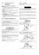
1.4. How to Discharge the E.Capacitor on Flash P.C.B. CAUTION: 1. Be sure to discharge the E.capacitor on FLASH P.C.B.. 2. Be careful of the high voltage circuit on FLASH P.C.B. when servicing. [Discharging Procedure] 1. Refer to the disassemble procedure and remove the necessary parts/unit. 2. Install the insulation tube onto the lead part of resistor (ERG5SJ102:1kΩ /5W). (An equivalent type of resistor may be used.) 3. Place a resistor between both terminals of E.capacitor on the FLASH P.C.B.
2 Warning 2.1. Prevention of Electrostatic Discharge (ESD) to Electrostatically Sensitive (ES) Devices Some semiconductor (solid state) devices can be damaged easily by static electricity. Such components commonly are called Electrostatically Sensitive (ES) Devices. The following techniques should be used to help reduce the incidence of component damage caused by electrostatic discharge (ESD). 1.
2.3. 2.3.1. Caution for AC Cord (For EB/GC) 2.3.2.1. Information for Your Safety Blue Brown IMPORTANT Your attention is drawn to the fact that recording of prerecorded tapes or discs or other published or broadcast material may infringe copyright laws. WARNING To reduce the risk of fire or shock hazard, do not expose this equipment to rain or moisture. CAUTION To reduce the risk of fire or shock hazard and annoying interference, use the recommended accessories only.
2.4. 2.4.1. How to Replace the Lithium Battery Replacement Procedure 1. Remove the MAIN P.C.B.. (Refer to Disassembly Procedures.) 2. Remove the Lithium battery (Ref. No. “B9101” at component side of MAIN P.C.B.) and then replace it into new one. NOTE: This Lithium battery is a critical component. (Type No.: ML614 Manufactured by Energy Company, Panasonic Corporation.) It must never be subjected to excessive heat or discharge.
3 Service Navigation 3.1. Introduction This service manual contains technical information, which allow service personnel’s to understand and service this model. Please place orders using the parts list and not the drawing reference numbers. If the circuit is changed or modified, the information will be followed by service manual to be controlled with original service manual. 3.2. 3.2.1.
3.3. General Description About Lead Free Solder (PbF) The lead free solder has been used in the mounting process of all electrical components on the printed circuit boards used for this equipment in considering the globally environmental conservation. The normal solder is the alloy of tin (Sn) and lead (Pb). On the other hand, the lead free solder is the alloy mainly consists of tin (Sn), silver (Ag) and Copper (Cu), and the melting point of the lead free solder is higher approx.
3.4. How to Define the Model Suffix (NTSC or PAL model) There are nine kinds of DMC-FZ150. • a) DMC-FZ150 (Japan domestic model) • b) DMC-FZ150P/PC • c) DMC-FZ150EB/EF/EG/EP • d) DMC-FZ150EE • e) DMC-FZ150GT • f) DMC-FZ150GK • g) DMC-FZ150GD • h) DMC-FZ150GN • i) DMC-FZ150GC/PU What is the difference is that the “INITIAL SETTINGS” data which is stored in Flash-ROM mounted on MAIN P.C.B.. 3.4.1.
3.4.2. INITIAL SETTINGS: After replacing the MAIN P.C.B., make sure to perform the initial settings after achieving the adjustment by ordering the following procedure in accordance with model suffix of the unit. 1. IMPORTANT NOTICE: Before proceeding Initial settings, make sure to read the following CAUTIONS. 2. PROCEDURES: • Precautions: Read the above "CAUTION 1" and "CAUTION 2", carefully. • Preparation: - Attach the Battery or AC Adaptor with a DC coupler to the unit.
[CASE 1. After replacing MAIN P.C.B.] [Except “EG, EF, EB and EP” models: (VEP56145A is used as a Main P.C.B.)] When MAIN P.C.B. has just been replaced, all of the model suffix is displayed as follows. (Four pages in total) [Only “EG, EF, EB and EP” models: (VEP56145B is used as a Main P.C.B.)] When MAIN P.C.B. has just been replaced, only 7 model suffix are displayed as follows. (Two pages in total) [CASE 2. Other than “After replacing MAIN P.C.B.”] • Step 5.
• Step 6. Set the model suffix in “INITIAL SETTINGS”: • Press the “[ RIGHT ] of Cursor buttons”. • The only set area is displayed, and then press the “[ RIGHT ] of Cursor buttons” after confirmation. (The unit is powered off automatically.) • Step 7. CONFIRMATION: Confirm the display of “PLEASE SET THE CLOCK” in concernd language when the unit is turned on again. When the unit is connected to PC with USB cable, it is detected as removable media.
4 Specifications 14
5 Service Fixture & Tools 5.1. When Replacing the Main P.C.B. After replacing the MAIN P.C.B., be sure to achieve adjustment. The service software is available at “TSN Website”. To download, click on “Support Information from NWBG/VDBG-AVC”. 5.2. Service Position This Service Position is used for checking and replacing parts. Use the following Extension cables for servicing. Table S1 Extension Cable List No. 1 2 Parts No.
6 Measurements and Adjustments The adjustment details are described in “Service Manual Vol.1” for this model. When the following part(s) located on the MAIN P.C.B is replaced., perform the same necessary adjustment items of MAIN P.C.B. *. IC6001 : VENUS *. IC6005 : Flash-Rom *. IC7101 : GYRO SENSOR 7 Maintenance 7.1. Cleaning Lens, Viewfinder and LCD Panel Do not touch the surface of lens, Viewfinder and LCD Panel with your hand. When cleaning the lens, use air-Blower to blow off the dust.
DSC1110051CE Service Manual S1.1. Important Safety Notice Diagrams and Replacement Parts List Digital Camera Model No. DMC-FZ150P DMC-FZ150PC DMC-FZ150PU DMC-FZ150EB DMC-FZ150EE DMC-FZ150EF DMC-FZ150EG DMC-FZ150EP DMC-FZ150GC DMC-FZ150GD DMC-FZ150GK DMC-FZ150GN DMC-FZ150GT S1. About Indication of The Schematic Diagram COMPONENTS IDENTIFIED WITH THE MARK HAVE THE SPECIAL CHARACTERISTICS FOR SAFETY. WHEN REPLACING ANY OF THESE COMPONENTS USE ONLY THE SAME TYPE. 1.
S2. Voltage Chart Note) Indicated voltage values are the standard values for the unit measured by the DC electronic circuit tester (high-impedance) with the chassis taken as standard. Therefore, there may exist some errors in the voltage values, depending on the internal impedance of the DC circuit tester. S2.1. Main P.C.B. REF No.
S3. Block Diagram S3.1.
S3.2. Video/Audio Process Block Diagram LCD IF P.C.B.
S3.3. Lens Drive Block Diagram FLASH P.C.B. IC6001 CO.
S3.4. Power Block Diagram CL9011 P9002 To BATTEY BAT+ 1 THERMO 2 BAT- 4 F1001 CL1010 CL9012 PW D1.2V CL1021 Q9101 PW D3.
S-7
S4. Schematic Diagram S4.1. Main Connection (MC) Schematic Diagram DMC-FZ150 Main Connection Section (Main P.C.B.
10k 10k R9072 R9073 G2 OFF LCD_CS 200 参考:TOP_OP回路 R9080 CL9021 CL9020 CL9019 CL9003 CL9002 CL9004 CL9014 CL9006 CL9015 CL9009 P CL9010 PW_BL_MINUS CL9008 P CL9001 PW_BL_PLUS FP9002 K1MY18BA0370 CL9013 D CL9016 LCD_ROTATE1 CL9007 TO TOP_OPERATION CL9005 2/4 ON CMD_DIAL_F1 18 CMD_DIAL_F0 17 KURUPON 16 D_GND 15 POWER_LED_K 14 POWER_LED_A 13 POWER_SW R9071 3900 R9074 3900 PW_D3R0V P CMD_DIAL_F1 D CMD_DIAL_F0 D PON_ON_L D POWER_LED_K D 12 POWER_ON_
BAT+ 1 UNREG+ P THERMO BAT- 2 BATT_THERMO D 4 ID_BAT_DQ D UNREG- P VA9020 G 2 MIC_L_IN 3 MIC_GND 4 LB9077 RL9002 TO MAICO CL9030 C9009 14 DATA2 13 DATA3 12 9 DATA6 8 DATA7 7 SDAT 6 SY EM SOUT 5 G_MIC_RIN SY SCLK 4 G_MIC_LIN SY SEN 3 SY EM GND 2 5V 1 MIC_GND C9002 F1G1E472A086 G2 15 DATA1 10 MIC_GND J0JCC0000397 J0JCC0000397 16 DATA0 11 J SY F1G1E472A086 G1 25V MIC_R_IN LB9076 25V 1 17 VALID DATA5 P HS R G1 MIC_GND 18 VSYNC 5V D_GN
$[18] D PW_SD3R0V P PW_SD3018V P SDCD SY SDWP D 7 SDDAT1 D 5 SDDAT0 D 3 G9002 PW_SD3R0V_CA1 SDDAT3 D 1 EVF_RESET SDDAT2 D SDCMD D SDCLK D D_GND P HS R G9001 R9032 22K 8 5 7 RX9001 D1H84734A024 R9031 1k 6.
MC L7001 G1C100MA0408 D A_FCLK 5 LRCLK 10V 10V C5019 F1G1A1040006 10V C5003 F1G1A1040006 10V C5018 F1G1A1040006 C5002 F1G1A1040006 CL5011 105 104 103 102 101 100 YHN YINP YPOS REFI REFO MREG OE 1B1 1B2 2B1 2B2 NC 2A(R) NC NC GND 2 3 4 5 6 7 Vcc 1 6.3V F1G0J1050007 EXT_MIC_ON_H D EM CL5017 G5001 MIC_GND R5001 $ CL5005 C5013 F1G0J1050007 LINEOUTR 90 6.
S-13
S4.3. Digital (D) Schematic Diagram DMC-FZ150 Digital Section (Main P.C.B.
2/4 R6023 $[18] R6025 $[18] G6014 A10 R6024 $[18] C6026 16V F1G1C1030008 D11 C6062 F1G1A1040006 C6045 10V $ 10V C6032 $[F1G1C1030008] AB10 AB11 AB22 F5 M20 J19 AD25 L11 M11 J16 N11 F6 N19 K19 AD26 L12 M12 J17 N12 E14 N20 K20 C25 L13 M13 J18 N13 E18 P19 J20 C26 B9 L14 M14 K7 P7 N14 P20 Y7 A3 A14 L15 M15 P8 K8 N15 AC5 Y8 A4 B14 L16 P9 M16 K9 N16 AC6 Y9 B3 C14 D14 P10 L17 M17 K10 N17 AE6 Y10 B4 P11 L18 M18 K11 N18 AB6 Y11 D24
MC BUS288_D0CM N23 1 C16 MC BUS288_D0DP P26 MC LCDOUT12 7 A15 MC BUS288_D0DM P25 5 B15 MC BUS288_D0EP P24 C15 MC BUS288_D0EM P23 D15 MC BUS288_D0FP R24 MC BUS288_D0FM R23 MC LCDOUT13 P PWM_BLT AE17 MC LCDOUT14 AD17 MC LCDOUT15 8 6 AF17 RX6054 D1H81014A024 4 STB_PWM 2 B16 LCDOUT11 SY MC EVF_CS AC17 MC EXT_STB_ON_L AF16 SY A_MCLK AE9 MC BUS288_D0GP T26 MC INT_STB_ON_L AE16 SY A_DCLK AF9 MC BUS288_D0GM T25 SY MC S_SYSCON_SCK AD16 SY A_D
P24 G22 24 F23 R22 T22 T4 T5 R6042 P23 IC6005 C3FBTY000020 R24 R23 R4 R6040 P25 ERJ G23 R6041 P26 $[ERJ N23 R5 N4 N5 T25 P4 1 48 T26 2 47 46 U26 REB I/O4 CEB VSS VSS WPM AE7 U17 G4 U18 U19 WEB I/O2 WPB I/O1 I/O0 GND V12 NC E17 NC V16 V17 V18 V19 W16 FRDT_3 FRDT_2 FRDT_1 FRDT_0 27 21 N3 W17 M3 W18 B25 W19 B26 Y13 A25 Y14 A26 Y15 A1 Y16 A2 Y17 B1 Y18 B2 Y19 AE1 C3 AE2 D4 AF1 D7 AF2 D8 AE25 E5 AE26 E7 AF25 E8 AF26 K4 K5
S4.4.
S-19
S4.5. Power (P) Schematic Diagram DMC-FZ150 Power Section (Main P.C.B. (5/9)) Schematic Diagram (P) 1/4 N 10V M C1001 F1H1A4750004 [18] R1006 $ 4mm S 3 D $[B1GBCFJN0041] QR1040 Q1071 B1CFHC000005 C1071 $[F1J1H105A449] 5 G 2 50V CH7 BL C1070 F1J1H105A449 6 G 1 D D1070 B0JCMD000066 S L L1070 G1C330MA0477 G 4 Q1040 $[B1CFHC000006] R1074 15K C1705 $[F1G1A2240008] CH6 5.
2/4 2.5A 32V CAUTION: FOR CONTINUED PROTECTION AGAINST FIRE HAZARD, REPLACE ONLY WITH THE SAME TYPE 2.5A 32V FUSE. ATTENTION: POUR UNE PROTECTION CONTINUE LES RISQUES D' INCENDIE N' UTILISERQUE DES FUSIBLE DE MÉME TYPE 2.5A 32V. 2.
PGND12 32 PGND12 31 CTL1235 30 Hx1 VBAT CMINUS VREGD RT SCP 14 SCP6OUT FB1 H [15]INV1 13 SCP6 VCC 12 FB2 10V Lx2 33 [27]Lx1 [28]Lx1 CPLUS 11 INV2 Hx2 34 HVREG 10 FB3 VREGA F1G1A473A032 C1006 CH4 2.
CH4 2.1V D2R1V SENSOR DCDC1R5V Vout Vss Vss 3 2 Vin Vout 1 R1045 $ $ R1047 IC1042 C0DBGYY00779 Vss 2 [18] CE Vin Vout 1 C1045 $[F1H1A4750004] 3 L1042 $[G1C4R7MA0477] 4 LX 1 6 (1.8V) Vin CL1042 CL1047 Vss 2 4 Vin Vout 1 10V MC PW_SE1R5V MC $ R1048 C1042 F1H1A105A025 CL1044 10V 3 CE PW_SE1R8V CL1043 F1H1A105A025 (1.
S4.6. EXT MIC (EM) Schematic Diagram G G_EX_MIC_LIN SY G_EX_MIC_RIN SY F C5203 6.3V R5205 68K C5204 F1G0J1050007 or 6.
S4.7.
S4.8.
S4.9.
R9122 C7017 C7016 C7015 R7015 R7014 R7013 R7020 G7001 4 1 IC1061 C1061 2 G9102 3 G7002 8 R9104 G9101 C7019 R1060 C5009 R9112 LB2003 R2002 R2001 1 2 4 3 LB2007 LB2004 L2001 LB2002 R2005 MK6 MK5 15 LB2005 19 D2001 9 10 5 1 R5217 5 G5006 R5025 R5026 R5219 R5218 R5220 R5214 R5201 R5203 R5207 R5213 R5211 R5212 C5208 F2001 LB2001 JK2001 C6029 1 R6045 RX2001 R5216 LB2008 C6002 RX2002 R5202 C2002 VA2002 VA2001 G5222 R5222 C5207 C5203 C5204 C5205 R520
2/4 C9014 R5026 R5218 R5220 R5201 LB9003 C5208 R5214 R5203 R5207 R5213 R5211 G5224 R5224 C9011 e R5025 C5206 R5212 C5201 LB9001 C9010 R5219 LB9002 C5202 G5223 R5223 e 3 R5204 R5210 e e R5209 R5208 Q5205 R5217 R5202 e Q5204 C5207 C5203 C5205 Q5202 R5216 R5215 C5204 R5205 R5206 e QR5202 Q5201 e QR5201 C5209 e Q5206 R5221 R2001 19 10 R9078 C1062 MK6 MK5 S-29 4 2 C1061 9 LB2001 3 1 R1060 3 IC1061 15 10 LB2002 R2005 4 5 L2001 11 R9117
R2001 LB2001 12 G9102 R70 C70 R7013 R2005 4 1 R1060 3 IC1061 C1062 G7001 R7020 R9078 C7019 R7009 R9106 C7015 R7014 Q9101 C9106 C7016 R7015 R9107 C9109 C9113 R9119 IC9103 C9108 R9118 VA9019 VA9007 VA9005 VA9004 VA9008 VA9009 VA9010 VA9011 VA9006 RL9104 VA9012 RL9101 RL9108 RL9107 R9122 R9121 C7017 R9120 RL70 R RL70 R R D1010 C1009 C1008 C102 R1103 R1005 C1101 R1013 14 R7016 4 C1014 RL9109 5 RL7006 3 13 H C1103 R7017 2 R1014 L1020 C1003 C1004
LB2001 1 R1060 3 IC1061 2 MK6 MK5 3 C1061 4 4 C1062 001 R9078 R2005 11 R2001 12 G9102 1 2 S9511 2 3 R9071 R9073 C9012 R9074 R9072 MK4 MK3 CL9020 CL9021 CL9019 R9511 V5 W5 Y5 AA5 AB5 AC5 AD5 AE5 AF5 U4 V4 W4 Y4 AA4 AB4 AC4 AD4 AE4 AF4 A3 B3 C3 D3 E3 F3 G3 H3 J3 K3 L3 M3 N3 P3 R3 T3 U3 V3 W3 Y3 AA3 AB3 AC3 AD3 AE3 AF3 A2 B2 C2 D2 E2 F2 G2 H2 J2 K2 L2 M2 N2 P2 R2 T2 U2 V2 W2 Y2 AA2 AB2 AC2 AD2 AE2 AF2 A1 B1 C1 D1 E1 F1 G1 H1
S5.1.2. Main P.C.B. Address Information Main P.C.B.
Main P.C.B. (2/2) G6020 G7001 G7002 G9001 G9002 G9101 G9102 C-14 H-10 I-11 C-18 C-18 I-11 I-11 F C C F F C C S9501 S9502 S9503 S9504 S9505 S9506 S9507 S9509 S9510 S9511 Switch D-19 C-19 C-20 C-19 B-19 C-19 D-19 E-20 G-18 G-17 F F F F F F F F F F Earth Terminal ET2001 D-11 F ET2002 B-15 F Address Information C.....Component Side F......
S-34
S6. Replacement Parts List Note: 1. * Be sure to make your orders of replacement parts according to this list. 2. IMPORTANT SAFETY NOTICE Components identified with the mark have the special characteristics for safety. When replacing any of these components, use only the same type. 3. Unless otherwise specified, All resistors are in OHMS, K=1,000 OHMS. All capacitors are in MICRO-FARADS (uf), P=uuF. 4. The marking (RTL) indicates the retention time is limited for this item.
DMC-FZ150EGK vol.2 Ref.No. ## ## B9101 C1001 C1002 C1003 C1004 C1005 C1006 C1007 C1008 C1009 C1010 C1014 C1015 C1020 C1023 C1024 C1030 C1040 C1041 C1042 C1043 C1051 C1060 C1061 C1062 C1063 C1064 C1070 C1073 C1101 C1103 C1201 C1203 C1301 C1303 C1401 C1403 C1501 C1511 C1512 C1601 C1701 C2001 C2002 C5002 C5003 C5005 C5006 C5007 C5009 C5010 C5012 C5013 C5018 C5019 C5020 C5021 C5201 C5202 C5203 C5204 C5209 C6001 C6002 C6003 C6004 C6005 C6006 C6007 C6010 C6021 C6022 Part No.
DMC-FZ150EGK vol.2 Ref.No. Part No. Part Name & Description Pcs CX6001 CX6002 CX6003 F5A84103A020 F5A84103A020 F5A84103A020 CAPACITOR NETWORKS CAPACITOR NETWORKS CAPACITOR NETWORKS 1 1 1 D1010 D1060 D1070 D2001 D8101 D8103 B0JCMD000066 B0JCMD000066 B0JCMD000066 B0JCCD000003 DZ2J082M0L B2ABAP000006 DIODE DIODE DIODE DIODE DIODE DIODE 1 1 1 1 1 1 ET2001 ET2002 K4ZZ01000300 EARTH TERMINAL K4AD01D00008 EARTH TERMINAL 1 1 K5H252YA0080 FUSE 1.5A K5H1522A0018 FUSE 1.
DMC-FZ150EGK vol.2 Ref.No. R6028 R6030 R6032 R6034 R6036 R6038 R6040 R6042 R6043 R6052 R6053 R6054 R6056 R6081 R6086 R6087 R7002 R7007 R7009 R7021 R8101 R8103 R8105 R8107 R8108 R8109 R8110 R8111 R8112 R8113 R9003 R9005 R9006 R9007 R9008 R9011 R9012 R9014 R9031 R9032 R9041 R9042 R9043 R9044 R9045 R9046 R9047 R9048 R9049 R9050 R9051 R9061 R9071 R9072 R9073 R9074 R9075 R9078 R9080 R9081 R9082 R9103 R9106 R9107 R9109 R9114 R9115 R9119 R9120 R9123 R9124 R9501 R9502 R9503 R9507 R9508 R9510 Part No.