MARCH 2000 IC050C IC171C RS422/485 Serial Interface Plus CUSTOMER SUPPORT INFORMATION Order toll-free in the U.S. 24 hours, 7 A.M. Monday to midnight Friday: 877-877-BBOX FREE technical support, 24 hours a day, 7 days a week: Call 724-746-5500 or fax 724-746-0746 Mail order: Black Box Corporation, 1000 Park Drive, Lawrence, PA 15055-1018 Web site: www.blackbox.com • E-mail: info@blackbox.
RS422/485 SERIAL INTERFACE PLUS FEDERAL COMMUNICATIONS COMMISSION AND INDUSTRY CANADA RADIO FREQUENCY INTERFERENCE STATEMENTS This equipment generates, uses, and can radiate radio frequency energy and if not installed and used properly, that is, in strict accordance with the manufacturer’s instructions, may cause interference to radio communication.
RS422/485 SERIAL INTERFACE PLUS NORMAS OFICIALES MEXICANAS (NOM) ELECTRICAL SAFETY STATEMENT INSTRUCCIONES DE SEGURIDAD 1. Todas las instrucciones de seguridad y operación deberán ser leídas antes de que el aparato eléctrico sea operado. 2. Las instrucciones de seguridad y operación deberán ser guardadas para referencia futura. 3. Todas las advertencias en el aparato eléctrico y en sus instrucciones de operación deben ser respetadas. 4. Todas las instrucciones de operación y uso deben ser seguidas. 5.
RS422/485 SERIAL INTERFACE PLUS 11. El aparato eléctrico deberá ser connectado a una fuente de poder sólo del tipo descrito en el instructivo de operación, o como se indique en el aparato. 12. Precaución debe ser tomada de tal manera que la tierra fisica y la polarización del equipo no sea eliminada. 13.
RS422/485 SERIAL INTERFACE PLUS Contents Chapter Page 1. Specifications....................................................................................................1 2. Introduction .....................................................................................................2 2.1 Overview..................................................................................................2 2.2 What’s Included......................................................................................
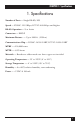
CHAPTER 1: Specifications 1. Specifications Number of Ports — Single RS-485/422 Speed — IC050C: 115.2 Kbps; IC171C: 460.8 kbps and higher RS-485 Operation — 2- or 4-wire Connectors — DB25P Maximum Distance — Up to 5000 ft. (1524 m) Communications Chip — IC050C: 16550 UART; IC171C: 16950 UART MTBF — >150,000 hours MTTR — <0.
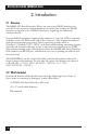
RS422/485 SERIAL INTERFACE PLUS 2. Introduction 2.1 Overview The RS422/485 Serial Interface Plus is an easy-to-use RS-485 interface for your PC. It incorporates unique hardware circuitry that enables the RS-485 interface to appear to be an RS-232 interface, requiring no additional software drivers. Previous RS-485 interfaces required the software to “turn on” RTS to transmit and then “turn off” RTS at the end of the character. This required overhead and special interrupt processing.
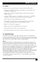
CHAPTER 2: Introduction 2.3 Features Listed below are the special features your Serial Interface Plus offers. • Single-channel RS-485/422 adapter for Windows, OS/2, Windows NT, and DOS communications. • Addressable as COM1: through COM4: or twelve other pre-selected address options. • Automatic RS-485 protocol control allows card to appear to be RS-232; therefore, no special drivers or additional software is required. • “PAL” allows for unique OEM address selection.
RS422/485 SERIAL INTERFACE PLUS RS-530 and RS-449 RS-530 and RS-449 (EIA-530 and EIA-449) are similar to RS-422 and RS-485 in the fact that they are differential interfaces, but these two standards provide a specified pin-out that defines a full set of modem control signals that can be used for regulating flow control and line status. RS-449 is defined on a standard 37-pin D sub-connector, while RS-530 is backward-compatible and is replacing RS-449. RS-530 is defined on a 25-pin D sub-connector.
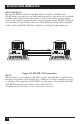
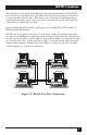
CHAPTER 2: Introduction This interface is ideal for multi-drop or network environments. The RS-485 tri-state driver (not dual-state) will allow the electrical presence of the driver to be removed from the line. The driver is in a tri-state or high-impedance condition when not active. Only one driver may be active at a time and the other driver(s) must be tri-stated. Some communication software packages refer to RS-485 as RTS enable or RTS block mode transfer.
RS422/485 SERIAL INTERFACE PLUS 3. Address Selection NOTE Be sure to set the address selections and jumper options before installation. The RS422/485 Serial Interface Plus occupies 8 consecutive I/O locations, and looks to the PC as a standard serial port. DIP switch SW1 sets the port address options. Be careful when selecting the port address, since some selections conflict with existing PC ports. The following table shows the addressing options available with the standard PAL.
CHAPTER 3: Address Selection ON OFF 1 2 3 4 A B C D Figure 3-1. DIP Switch SW1. Address 3F8 Hex.
RS422/485 SERIAL INTERFACE PLUS 4. Option Selection NOTE Be sure to set the address selections and jumper options before installation. The RS422/485 Serial Interface Plus contains several jumpers that must be set for proper operation. E1: This header selects the interrupt request for the RS422/485 Serial Interface Plus. If COM1: is selected, this jumper must be on the IRQ4 setting. If COM2: is selected, this jumper must be on IRQ3.
CHAPTER 4: Option Selection 2 3 4 5 7 10 11 12 15 Figure 4-2. Header E1 Optional Windows 3.1 Configuration. IRQ 10 selected. (Refer to Chapter 6 for more information.) NOTE IRQ 2 on AT class machines is not available. IRQ 9 is substituted in place of IRQ 2. To select IRQ 9, place the jumper on the IRQ 2 position. M S N E2: “N” indicates the (N)ormal, single-interrupt-per-port mode. The “S” indicates the (S)hared interrupt mode, which allows more than one port to access a single IRQ.
RS422/485 SERIAL INTERFACE PLUS M M S N N S Figure 4-4. Header E2 in Shared Mode. Header E5 is used to control the RS-485 enable/disable functions for the driver circuit. One of the unique features of the RS422/485 Serial Interface Plus is its ability to be RS-485 compatible without the need for special software or drivers. This is especially useful in Windows, Windows NT, and OS/2 environments where the lower level I/O control is abstracted from the application program.
CHAPTER 4: Option Selection Header E3 is used to control the RS-485 enable/disable functions for the receiver circuit. The RS-485 “Echo” is the result of connecting the board’s receiver inputs to the transmitter outputs. Every time a character is transmitted it is also received by the board. This can be beneficial if your software can handle it (using received characters to throttle the transmitter), or it can confuse your system if your software cannot handle it.
RS422/485 SERIAL INTERFACE PLUS DIP shunt E4 selects the pin out for the DB25 connector P3.
CHAPTER 4: Option Selection Signal GND TDB TDA RDB RDA Name TX+ TXRX+ RX- Ground Transmit Positive Transmit Negative Receive Positive Receive Negative Pin # 7 24 25 12 13 Mode Output RS-422 Output RS-422 Input RS-422 Input RS-422 RS-530/422/485 Line Termination Typically, each end of the RS-530/422/485 bus must have line-terminating resistors. A 100-ohm resistor is across each RS-530/422/485 input, in addition to a 1K ohm pull-up/pull-down combination that biases the receiver inputs.
RS422/485 SERIAL INTERFACE PLUS ON OFF 1 T 2 3 4 5 P P L L Figure 4-11. DIP Switch SW2.
CHAPTER 5: Installation 5. Installation IMPORTANT You MUST set up the operating system BEFORE you physically install the Card. 5.1 Software Installation If you are installing an ISA adapter in DOS, OS/2®, or QNX, please refer to the appropriate directory on one of the Serial Utilities Disks for instructions. 5.1.1 WINDOWS 3.1X Please refer to the /WINDOWS sub-directory on the Serial Utilities Diskette for help files and current information on the installation of the Card in this operating environment.
RS422/485 SERIAL INTERFACE PLUS NOTE Be sure to set the address selections and jumper options before installation. 1. Turn off PC power. Disconnect the power cord. 2. Remove the PC case cover. 3. Locate an available slot and remove the blank metal slot cover. 4. Gently insert the Card into the slot. Make sure that the Card is seated properly. 5. Replace the screw. 6. Replace the cover. 7. Connect the power cord. Installation is complete.
CHAPTER 6: Windows 3.1 Configuration 6. Windows 3.1 Configuration To configure the RS422/485 Serial Interface Plus under Windows 3.1, open the “Control Panel,” which is typically found in the “Main” Program Group. Next, open the “Ports” selection under the Control Panel. Control Panel Settings Color Help Fonts International Data/Time Ports Network Mouse 386 Enhanced Desktop Keyboard Drivers Sound Fonts Specifies communications settings for serial ports Select the port you wish to configure.
RS422/485 SERIAL INTERFACE PLUS The next step is to select the appropriate Baud Rate, Data Bits, Parity, Stop Bits, and Flow Control. Settings for COM3: Baud Rate: 19200 Data Bits: 8 Parity: None Stop Bits: 1 Flow Control: None OK Cancel Advanced Help If you wish to select an IRQ or address different from the default, click on the “Advanced” button.
CHAPTER 6: Windows 3.1 Configuration Select “OK” for all windows after you have made your selection. The following message should appear: System Setting Change Your COM Port settings have changed: You will need to quit and restart Windows so that the new setting(s) can take effect. Don't Restart Now Restart Now If you wish to configure another COM Port setting, select the “Don’t Restart Now” button and repeat this procedure until you have configured all new ports.
RS422/485 SERIAL INTERFACE PLUS 7. Troubleshooting Computer does not recognize any COM ports, or the system is “dead” or non-responsive. How to identify the problem: Use the SSD.COM Program (found on your utility diskette). Solution: Identify all COM ports installed on you computer and address the RS422/485 Serial Interface Plus at a different address from those already present. Reason: Only one device can occupy an address location.
CHAPTER 7: Troubleshooting When using Windows 3.1, only two ports at any time are functional. How to identify the problem: Verify that all ports have a separate interrupt, or if sharing interrupts, only one device is using the IRQ at a time. Solution: Change the IRQs so that each port has its own unique interrupt (the preferred setting) or close each port before trying to open the next. Reason: The Windows communication driver does not support simultaneous operation of shared interrupts. In Windows 3.
RS422/485 SERIAL INTERFACE PLUS The RS422/485 Serial Interface Plus is setup to use the AT interrupts, but there’s no interrupt response. How to identify the problem: Verify that the interrupt jumpers are correctly set. Verify that the card is inserted into a 16-bit or AT slot. Solution: Use the program SLT (found on your utility diskette) to verify that the interrupts are set correctly. (Note that SLT requires that the transmit and receive signals on the connector be “looped back” or connected together.
CHAPTER 7: Troubleshooting 7.1 Calling Black Box If you determine that your RS422/485 Serial Interface Plus is malfunctioning, do not attempt to alter or repair the unit. It contains no user-serviceable parts. Contact Black Box Technical Support at 724-746-5500. Before you do, make a record of the history of the problem. We will be able to provide more efficient and accurate assistance if you have a complete description, including: • the nature and duration of the problem. • when the problem occurs.
C1 D1 E2 U4 R1 SLS08-22V10 NS M 74193 74193 16550 C5 U5 SLS07-22V10 ABCD 74LS74 P1 AUTO RTS 422 R2 RX E3 C9 E4 R15 75174 R4 75173 74LS245 R3 C7 TPPLL R17 E1A530 SW2 C3 C2 E1 SW1 Y1 U6 RP1 1 C8 U7 U3 U2 C4 U1 P2 2 3 4 5 7 10 11 12 15 S10485 R18 R6 R5 P3 25 13 C6 R7 R8 R9 R10 R11 R12 R13 U9 R14 24 U8 E5 AUTO RTS 422 R16 TX RS422/485 SERIAL INTERFACE PLUS Appendix: Circuit-Board Design 14 1
© Copyright 2000. Black Box Corporation. All rights reserved.