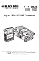
IC476A-F-R2 IC476A-M-R2 IC477A-F-R2 FEBRUARY 1998 IC477A-M-R2 IC478A-F-R2 IC478A-M-R2 Async 232↔422/485 Converter -R2 7A-M 485 : IC47 c 232↔r Codeem: AsCyonnverte It S/N: -R2 A-M 476 ↔485 : ICsync 23r2 e d te Co m: Aonver C Ite : S/N CUSTOMER SUPPORT INFORMATION -R2 8A-M 485 : IC47 c 232↔r Codeem: AsCyonnverte It S/N: Order toll-free in the U.S. 24 hours, 7 A.M.
ASYNC 232↔422/485 CONVERTER FEDERAL COMMUNICATIONS COMMISSION AND CANADIAN DEPARTMENT OF COMMUNICATIONS RADIO FREQUENCY INTERFERENCE STATEMENTS This equipment generates, uses, and can radiate radio frequency energy and if not installed and used properly, that is, in strict accordance with the manufacturer’s instructions, may cause interference to radio communication.
ASYNC 232↔422/485 CONVERTER NORMAS OFICIALES MEXICANAS (NOM) ELECTRICAL SAFETY STATEMENT INSTRUCCIONES DE SEGURIDAD 1. Todas las instrucciones de seguridad y operación deberán ser leídas antes de que el aparato eléctrico sea operado. 2. Las instrucciones de seguridad y operación deberán ser guardadas para referencia futura. 3. Todas las advertencias en el aparato eléctrico y en sus instrucciones de operación deben ser respetadas. 4. Todas las instrucciones de operación y uso deben ser seguidas. 5.
ASYNC 232↔422/485 CONVERTER 11. El aparato eléctrico deberá ser connectado a una fuente de poder sólo del tipo descrito en el instructivo de operación, o como se indique en el aparato. 12. Precaución debe ser tomada de tal manera que la tierra fisica y la polarización del equipo no sea eliminada. 13.
ASYNC 232↔422/485 CONVERTER Contents 1. Specifications ...............................................................................................5 2. Introduction ................................................................................................7 3. Configuration ..............................................................................................8 3.1 Setting the DTE/DCE Switch................................................................9 3.2 DIP-Switch Configuration .......
CHAPTER 1: Specifications 1.
ASYNC 232↔422/485 CONVERTER Humidity Altitude Power Size Shipping Weight 6 5 to 95%, noncondensing Up to 10,000 feet (3048 m) Draws operating power from RS-232 data and control signals; no AC power or batteries required 2.7"H x 2.1"W x 0.7"D (6.9 x 5.3 x 1.8 cm) <1 lb. (<0.
CHAPTER 2: Introduction 2. Introduction The Async 232↔422/485 Converter provides exceptional versatility in a compact package. Requiring no AC power or batteries for operation, the Converter supports asynchronous data rates up to 115.2 Kbps over one or two unconditioned unshielded, solid-copper-core twisted pair. The Converter passes one control signal in each direction (see explanation in Section 4.4) and can handle up to 31 terminal drops in a multipoint polling environment.
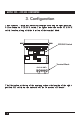
ASYNC 232↔422/485 CONVERTER 3. Configuration The Async 232↔422/485 Converter is configured using an eight-position DIP switch and a DTE/DCE switch. The figure below shows the DTE/DCE switch location, along with the location of the terminal block. DTE/DCE Switch DCE DTE Terminal Block +RCV-G-XMT+ The illustration at the top of the next page shows the location of the eightposition DIP switch on the underside of the Converter’s PC board.
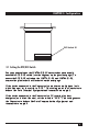
CHAPTER 3: Configuration DIP Switch S1 ON 1 2 3 4 5 6 7 8 3.1 Setting the DTE/DCE Switch For your convenience, the IC476A-X-R2 Converter has an externally accessible DTE/DCE switch (see the diagram on the previous page). To access the DTE/DCE switch on the IC477A-X-R2 and IC478A-X-R2, remove the plastic shells as illustrated on the next page. If the device connected to the Converter is a modem or multiplexor (or is wired like one), set the switch to “DTE.
ASYNC 232↔422/485 CONVERTER 3.2 DIP-Switch Configuration The eight positions on switch set S1 (shown in the first illustration below) configure the Converter for RTS/CTS delay (used in 2-wire, half-duplex mode only), echo mode (used in 2-wire, half-duplex mode only), method of carrier control, “transmit off” impedance, receive impedance, and 2-wire/ 4-wire operation. These switches are located internally on the underside of the Converter’s PC board.
CHAPTER 3: Configuration 3.2.1 DIP-SWITCH SETTINGS The factory-default settings for the switches are presented below. Read the information following the table for an explanation of the switch’s function. Switch S1 Summary Table Function Position S1-1* S1-2* S1-3 S1-4 S1-5 S1-6 S1-7* S1-8* “Transmit Off” Impedance “Transmit Off” Impedance RTS/CTS Delay Echo Mode Carrier Control Receive Impedance 2 wire/4 wire 2 wire/4 wire Factory Default Off Off On Off On On On On High Z 8 msec.
ASYNC 232↔422/485 CONVERTER S1-4: Echo Mode The setting for switch S1-4 determines whether the Converter echoes data back to the transmitting device (half-duplex mode only). S1-4 Setting On Echo On Off Echo Off S1-5: Carrier-Control Method The setting for switch S1-5 determines whether the carrier is “Constantly On” or “Controlled by RTS.” This setting allows for operation in switchedcarrier, multipoint, or hardware-handshaking applications.
CHAPTER 3: Configuration 3.2.2 CONFIGURATION SWITCH APPLICATIONS The table below shows you how to set the Converter’s switch to fit several common applications. Do not change switch settings until you have carefully read this manual. If you have any questions about the proper settings for your application, call your supplier for technical support. Switch Settings Typical Switch Applications Point-to-Point 4W 4W HDX 2W “Xmt Off” Imp. (S1-1) “Xmt Off” Imp.
ASYNC 232↔422/485 CONVERTER 4. Installation Once you have properly set the configuration switches, you are ready to connect the Converter to your system. This chapter tells you how to properly connect the Converter to the RS-485 and RS-232 interfaces. 4.1 Connection to the RS-485 Interface To function properly, the unit must have one or two twisted pairs of metallic wire. These pairs must be dry (unconditioned) metallic wire, between 19 and 26 AWG solid copper core (not stranded).
CHAPTER 4: Installation 2) It is not necessary that the RS-485 device adhere to the RS-530 standard. However, you must make sure that the signals, polarities, and pairing of your connection conform to this table. 3) If you are not using two IC477A-X-R2s or IC478A-X-R2s back to back and the procedure on the previous page produces garbage data (or none at all), flip the “A” and “B” leads at one end of the 485 connection. 4.1.
ASYNC 232↔422/485 CONVERTER 5. Connect the other pair of wires to RCV+ and RCV- on the terminal block, again making careful note of which color is positive, and which color is negative. NOTE Positive and negative are relative terms and may not always have the same relationship for all RS-422 or RS-485 devices (see the previous note regarding “flipping the leads”). Ultimately, you will want to construct a two-pair crossover cable that makes a connection with the RS-485 device as shown below.
CHAPTER 4: Installation +RCV-G-XMT+ Place the two halves of the strain-relief assembly on either side of the twisted-pair wire and press together very lightly. Slide the assembly so that it is about two inches (5.1 cm) from the terminal posts and press together firmly. 8. +RCV-G-XMT+ Insert the strain-relief assembly with the wire going through it into the slot in the bottom half of the modem case and set it into the recess in the case. 9.
ASYNC 232↔422/485 CONVERTER Bend the top half of the case as necessary to place it over the strainrelief assembly. Do not snap the case together yet. 10. Insert one captive screw through a saddle washer, then insert the captive screw with the washer on it through the hole in the DB25 end of the case. Snap that side of the case closed. Repeat the process for the other side. Cable installation is complete. 11. 4.1.3 2-WIRE CONNECTION Some RS-485 devices employ a two-wire, half-duplex configuration.
CHAPTER 4: Installation 4.2 Connection to the RS-232 Interface Once you have properly configured the Converter and connected the twisted-pair wires correctly, simply plug the Converter directly into the DB25 port of the RS-232 device. After doing so, remember to insert and tighten the two captive connector screws. NOTE If you must use a cable to connect the Converter to the RS-232 device, make sure it is a straight-through cable of the shortest possible length. We recommend no more than 6 ft. (1.8 m). 4.
ASYNC 232↔422/485 CONVERTER 4.4 Operation Once the Converter is properly installed, it should operate transparently— as if it were a standard cable connection. Operating power is derived from the RS-232 data and control signals; there is no ON/OFF switch. All data signals from the RS-232 and RS-485 interfaces are passed straight through. Additionally, in DCE mode, a Transmitter ON signal received at the RS-422/485 RCV connection will cause DCD output at the RS-232 connector to assert HIGH.
APPENDIX A: RS-232C Pin Configurations Appendix A. RS-232C Pin Configurations DIRECTION STANDARD “DCE” SETTING DIRECTION 1- (FG) Frame Ground 2- (TD) Transmit Data To Converter 3- RD) Receive Data FromConverter 4- (RTS) Request to Send To Converter DIRECTION Data Term.
ASYNC 232↔422/485 CONVERTER Appendix B. 422/485 (530) Pin Configuration The pinout below applies to models IC477A-F-R2, IC477A-M-R2, IC478A-F-R2, IC478A-M-R2. Pin Number 2 3 14 16 4 5 6 8 10 13 19 20 22 23 Pin Name TXA (positive) RXA (positive) TXB (negative) RXB (negative) RTS A (positive)* CTS A (positive) DCE Ready A (positive) Rcv. Line Signal Detect A (positive)* Rcv.
APPENDIX C: Self-Test Appendix C. Self-Test 1) To perform a self-test/functionality test of the units, set the 8-position DIP switch for 4W point-to-point operation (see the chart in Section 3.2.2). 2) Using two short pieces of twisted-pair cable, connect one wire between XMT+ and RCV+. Connect the other wire between XMT- and RCV-. 3) Send data from the RS-232 device. Whatever you send out you should receive back. 4) If you receive nothing back... a) there’s not enough (or any) power to the Converter.
© Copyright 1998. Black Box Corporation. All rights reserved.