® ® NETWORK SERVICES KV0004A KV0004A-LED KV0004A-XTRA-LED ServSwitch™ Freedom Control up to four computer systems and their displays, and share peripherals among them. Now with Glide and Switch automatic switching technology. Customer Support Information Order toll-free in the U.S.: Call 877-877-BBOX (outside U.S.
ServSwitch Freedom Trademarks Used in this Manual Black Box and the Double Diamond logo are registered trademarks, and ServSwitch is a trademark, of BB Technologies, Inc. Mac is a registered trademark of Apple Computer, Inc. Linux is registered trademark of Linus Torvalds. Windows is a registered trademark of Microsoft Corporation. NetWare is a registered trademark of Novell, Inc. Sun is a trademark of Sun Microsystems, Inc. Unix is a registered trademark of UNIX System Laboratories, Inc.
FCC and IC RFI Statements Federal Communications Commission and Industry Canada Radio Frequency Interference Statements This equipment generates, uses, and can radiate radio-frequency energy, and if not installed and used properly, that is, in strict accordance with the manufacturer’s instructions, may cause interference to radio communication.
ServSwitch Freedom Instrucciones de Seguridad (Normas Oficiales Mexicanas Electrical Safety Statement) 1. T odas las instrucciones de seguridad y operación deberán ser leídas antes de que el aparato eléctrico sea operado. 2. Las instrucciones de seguridad y operación deberán ser guardadas para referencia futura. 3. Todas las advertencias en el aparato eléctrico y en sus instrucciones de operación deben ser respetadas. 4. Todas las instrucciones de operación y uso deben ser seguidas. 5.
Table of Contents Contents 1. Specifications............................................................................................................................................................................... 6 2. Overview..................................................................................................................................................................................... 7 2.1 Introduction..............................................................................
ServSwitch Freedom 1. Specifications Approvals: CE, FCC Hardware Compatibility: All computers with USB interfaces Software Compatibility: Operates with all known software and operating systems including Windows®, Linux®, Unix®, BSD, all Sun® OS, all Mac® OS, NetWare®, etc. Connectors: Keyboard/Mouse: Switched USB: Audio: Other: USB Type A female USB 2.0 Type A female 3.
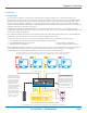
Chapter 2: Overview 2. Overview 2.1 Introduction The ServSwitch™ Freedom is a compact unit created to allow a single operator to access information and control operations across numerous systems and screens. With the ServSwitch Freedom unit, you can use a single USB keyboard and USB mouse to fulfill functions that previously required four separate sets. This provides immediate savings in both desk space and also the time required to access and control up to four systems and screens.
ServSwitch Freedom 2.2 Features Multiple screens, multiple systems The ServSwitch Freedom unit allows you to control up to four individual computer systems and their display screens using just one keyboard and mouse set. You can also share two further USB peripherals between the systems.
Chapter 2: Overview 2.5 Hardware Description 2.5.1 Top Panel Figure 2-2 shows the top panel of the unit. Table 2-1 describes its components: COMPUTER K/M SPK USB1 USB2 MODE S e r v S w i t c h F r e e d o m™ B L A C K 2 1 B OX D E S K TO P K V M S W I T C H 3 Figure 2-2. Top panel. Table 2-1. Top panel components. Number Component 1 COMPUTER button 2 Indicators Description Press to change to the next computer channel.
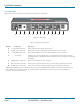
ServSwitch Freedom 2.5.2 Rear Panel Figure 2-3 shows the rear panel of the unit. Table 2-2 describes its components: 4 INDOOR USE O N LY 3 2 1 5V 2.5A OPTIONS 4 5 6 7 8 9 8 9 8 9 8 9 10 Figure 2-3. Rear panel. Table 2-2. Rear panel components. Number Component Description 4 2.5-mm Barrel connector 5 (2) USB Type A connectors Connect the console’s USB keyboard and mouse to these connectors. 6 3.
Chapter 3: Installation 3. Installation 3.1 Locations Please consider the following important points when planning the position of the ServSwitch Freedom unit: • Situate the ServSwitch Freedom unit close to the systems to which it will be connected and near to a power outlet. • Thanks to the optional remote control, the ServSwitch Freedom unit can be situated out of sight within the cabling cradle of a desk or placed adjacent to the connected systems.
ServSwitch Freedom 3.3 Connections Connections do not need to be carried out in the order given within this guide; however, where possible connect the power in as a final step. 3.3.1 User console The ports that make up the user console are where you attach the peripherals that will be shared between the computer systems. Ensure that power is disconnected from the unit. To connect peripherals to the user console 1.
Chapter 3: Installation 4. Audio: Where required, connect the lead from your speakers to the audio socket. See Figure 3-3. IN DO US OR ON E LY 5V 2.5 A OP TIO NS Figure 3-3. Connecting speakers to the user console. 3.3.2 Computer systems Each computer system is connected to the ServSwitch Freedom unit using (up to) two cables. To connect a computer system 1. Ensure that power is disconnected from the ServSwitch Freedom unit and the system to be connected. 2.
ServSwitch Freedom 3.3.3 Power in connection The ServSwitch Freedom unit is supplied with a 12.5W power adapter. There is no on/off switch on the unit, so operation begins as soon as a power adapter is connected. To connect the power supply 1. Attach the output lead from the power adapter to the 5V socket on the rear panel of the unit. See Figure 3-5. IN DO US OR ON E LY 5V 2.5 A OP TIO NS Figure 3-5. Attaching the power adapter lead to the power input socket. 2.
Chapter 3: Installation 3.3.4 Channel switching by external control The OPTIONS port allows external control of the current channel by commands sent either via RS-232 serial input or by switching one of the four channel select input lines. For more details about the necessary RS-232 serial cable, see Appendix C. 3.3.4.1 OPTIONS port pinout The OPTIONS port can accept either 8p8c or 10p10c connectors, as required. See Figure 3-7.
ServSwitch Freedom 3.3.4.
Chapter 3: Installation 3.3.5 Optional LED indicator connections The optional ServSwitch Freedom LED Monitor module (part number: KV0004A-LED) enables you to add LED (Light Emitting Diode) indicators to each of your video display screens to show which are active. Note: The ServSwitch Freedom switch requires firmware version 2.0 or later to be installed. Please see 4.7 Performing upgrades for details about how to check.
ServSwitch Freedom 2. Link each LED indicator to a port on the ServSwitch Freedom LED Monitor module - ports 1 to 4 are most commonly used. See Figure 3-10. Note: The KV0004A-LED kit includes four LED indicator assemblies. Up to ten can be connected and additional LED indicators can be ordered using the part number: KV0004A-XTRA-LED.
Chapter 4: Configuration 4. Configuration 4.1 Using the Configuration Menu The configuration mode allows you to determine numerous aspects of the ServSwitch Freedom unit capabilities. To use the configuration menu During normal use, the seven segment display on the front panel shows the number of the currently selected computer channel. From this condition, enter configuration mode as follows: 1. Press and hold the front panel COMPUTER button for roughly five seconds. The display will show: C 2.
ServSwitch Freedom Table 4-1.
Chapter 4: Configuration 4.2 General configuration 4.2.1 Changing hotkeys ServSwitch Freedom units use CTRL and ALT as their standard hotkeys. These can be changed if they clash with other software or hardware within the installation. To change the hotkeys 1. Enter the Configuration menu (see Section 4.1 for details). 2.
ServSwitch Freedom 4.2.4 Switching mode Using the configuration menu, you can define a default switching mode. The switching mode determines which peripherals (KVM, USB1, USB2 and/or speakers) should be moved to the next computer when it is selected using any of the standard methods. Regardless of the default switching mode set here, during use you can always change the mode using either the MODE button (on the front panel) or using the additional hotkey press combinations.
Chapter 4: Configuration 4.2.5 Miscellaneous functions To reset configuration to factory defaults 1. Enter the Configuration menu (see Section 4.1 for details). 2. Press F to enter the Functions menu 3. Press 8 and then Enter. The display will show r momentarily. 4. Press E and then Enter to exit the menu and save changes. To show the current firmware version 1. Enter the Configuration menu (see Section 4.1 for details). 2. Press F to enter the Functions menu 3. Press 1 and then Enter.
ServSwitch Freedom 4.3 Glide and Switch configuration 4.3.1 Installing the Glide and Switch configuration application The Glide and Switch configuration application is available for download from the Black Box website. Go to the KV0004A product page and click on the 'Resources' tab. 1. Install the application onto any computer (not necessarily one of the four computers linked to the ServSwitch Freedom unit) that has a vacant serial port.
Chapter 4: Configuration 3. Double-click on each screen representation to set the screen resolution and, optionally, add a screen name and/or configure an LED indicator (if used). See Figure 4-3. Figure 4-3. Defining the resolution of a screen and (optionally) a name The screen resolutions are not critical but they enable the ServSwitch Freedom unit to accurately map the movement of the mouse onto corresponding movements of the pointer across the screens.
ServSwitch Freedom 4.4 Multi-Monitor Glide and Switch configuration (Windows only) 4.4.1 Installing drivers and multi-monitor config app In order to use Multi-Monitor mode you will need to install a Multi-Monitor Glide and Switch driver (available for download from the Black Box website. Go to the KV0004A product page and click on the 'Resources' tab) onto each PC that has multiple monitors attached. 1. On each multiple monitor PC, run the downloaded file.
Chapter 4: Configuration 4.4.2 Configuring multiple monitors Multi-Monitor configuration is similar to normal Glide and Switch setup except that you can add more than one display per PC, up to a total of eight per machine. Note: It is necessary to install a driver on each PC that has multiple displays - see 4.4.1 Installing drivers and multi-monitor config app opposite. 1. Use the supplied flash upgrade cable to link the computer serial port to the ServSwitch Freedom OPTIONS port.
ServSwitch Freedom 4.5 Configuring LED indicators When the optional ServSwitch Freedom LED Monitor indicator kit is used, there are several configuration options available that allow you to customise behavior and these are set using the Glide and Switch configuration application. 4.5.1 Adjusting color and brightness for all indicators If necessary, you can impose default color and brightness settings upon all connected LED monitor indicators. Choose the Configure > LEDs...
Chapter 4: Configuration 3. For a newly added screen the LED: entry will show No LED. Click on the drop down handle and choose the LED indicator that you wish to associate with the currently selected video display screen. See Figure 4-7. Each entry within the LED: list relates to one of the ten output sockets on the ServSwitch Freedom LED Monitor module. Note: It is possible to associate any LED indicator with more than one video screen. Figure 4-7. Choosing an individual indicator port 4.
ServSwitch Freedom 4.6 Optional Glide and Switch operations and settings 4.6.1 Downloading the existing layout from the ServSwitch Freedom If the ServSwitch Freedom unit has already been configured and you wish to alter it (and you don’t have a saved .ffc config file), use the Configure > Receive Layout from Switch option to retrieve the current configuration from the ServSwitch Freedom. 4.6.2 Mouse...
Chapter 4: Configuration 4.7 Performing upgrades (Windows only) The ServSwitch Freedom unit is fully upgradable via flash upgrade. Such upgrades require a Windows-based computer system to be linked via the OPTIONS port. Items required to perform an upgrade • Upgrade cable (supplied Flash Upgrade Adapter plus a CAT5 patch lead [see Appendix C for overall pin-out specifications]). • A Windows-based upgrade computer with an RS-232 serial port.
ServSwitch Freedom 7. From the main KVM Firmware Uploader dialog, click the Browse... button and select the upgrade file: FREEDM_xxx.txt where xxx is the firmware version. The upgrade file details will be displayed within the dialog. IMPORTANT: Check that the ‘Intended Target Units’ field matches the ‘Unit Connected’ field. If these fields do not match then you may have an incorrect upgrade file; check with Black Box Technical Support before proceeding.
Chapter 5: Operation 5. Operation 5.1 Selecting a computer There are five ways to switch the common peripherals to specific computer channels: • Using the innovative Glide and Switch automatic switching utility • Using the front panel controls • Using hotkeys • Using mouse button presses • Using external switching control (RS-232 or input lines) 5.1.
ServSwitch Freedom 5.1.2 Selecting a computer using the front panel The front panel allows you to determine how the various peripherals are switched to one or more computer channels.
Chapter 5: Operation 5.1.3 Selecting a computer using hotkeys Using hotkey combinations, you can quickly switch the keyboard, mouse, speakers and USB peripherals to any computer channel. There are two mains ways to use hotkeys: Standard and Additional. 5.1.3.1 Using standard hotkey press combinations The standard hotkey press combinations allow you to change channels with the minimum of keypresses: 1. Simultaneously press and hold CTRL and ALT (or other hotkeys, if altered). 2.
ServSwitch Freedom 5.1.3.2 Using additional hotkey press combinations In addition to the standard hotkey press combinations (shown left), you can also add additional keypresses in order to determine which peripherals are switched: 1. Simultaneously press and hold CTRL and ALT. 2. Press and release a command key: A to switch all peripherals K to switch only the keyboard and mouse S to switch only the speakers U to switch only USB1 and USB2 3.
Chapter 5: Operation 5.2 Locking access to the computers When privacy is required, you can lock access to the connected computers via the unit. To lock the unit 1. Simultaneously press and hold CTRL and ALT (or other hotkeys, if altered). 2. While still holding CTRL and ALT, press L. The display will show P (providing a valid password has been previously set). You will not be able to access any computers until the password is correctly entered.
ServSwitch Freedom Appendix A. What is True Emulation? True Emulation represents a significant breakthrough in sharing USB devices between two or more computer systems. Until this point, the problem has been how to create a USB switch that provides all of the following: • Quick, transparent and reliable switching, • Accurate representation of the connected USB keyboard and mouse, • Switching control via the connected USB keyboard and/or mouse.
Appendices True Emulation is not necessarily required by other USB devices, which is why you will also find two enumerated circuits included (shown in green within the block diagram) alongside the True Emulation feature (shown in blue). This allows those other USB devices to operate at their highest speeds, without any intervention. The enumerated circuits benefit greatly from the USB Hubs that are jointly used with the True Emulation system.
ServSwitch Freedom Appendix B. What is Glide and Switch? Glide and Switch represents true innovation in KVM switching. For the first time, Glide and Switch allows users to automatically switch between target computers simply by moving the mouse pointer from screen to screen. What makes this such a revolution is that you no longer need software to be installed on your mission critical computers in order to do this.
Appendices Appendix C. Cable pin-outs The OPTIONS port uses a 10p10c socket which can accommodate both 10p10c connectors as well as the much more common 8p8c connectors, which are used on Ethernet leads and patch cables. The pin-outs are listed in this section for both types of connectors.
Appendices Appendix D. Safety information • For use in dry, oil free indoor environments only. • Both the unit and its power supply generate heat when in operation and will become warm to the touch. Do not enclose them or place them locations where air cannot circulate to cool the equipment. Do not operate the equipment in ambient temperatures exceeding 40 degrees Centigrade. Do not place the products in contact with equipment whose surface temperature exceeds 40 degrees Centigrade.
Black Box Tech Support: FREE! Live. 24/7. Tech support the way it should be. Great tech support is just 20 seconds away at 724-746-5500 or blackbox.com. ® ® NETWORK SERVICES About Black Box Black Box Network Services is your source for more than 118,000 networking and infrastructure products. You’ll find everything from cabinets and racks and power and surge protection products to media converters and Ethernet switches all supported by free, live 24/7 Tech support available in 20 seconds or less.