KVP4004A ServSwitch™ 4site Flex Simultaneously display four different analog/ BLACK BOX digital video sources on one screen, while supporting either USB or PS/2 keyboards and mice. ® Supports full-screen mode, quad-screen mode, PiP, and windows mode. Customer Support Information Order toll-free in the U.S.: Call 877-877-BBOX (outside U.S.
Trademarks Used in this Manual Trademarks Used in this Manual Black Box and the Double Diamond logo are registered trademarks, and ServSwitch is a trademark, of BB Technologies, Inc. 3M and MicroTouch are registered trademarks of 3M Company. AccuTouch, IntelliTouch, ELO, and Carroll Touch are registered trademarks of ELO Touch Solutions, Inc. TOSLINK is a registered trademark of Kabushiki Kaisha Toshiba, doing business as Toshiba Corporation.
FCC and IC RFI Statements Federal Communications Commission and Industry Canada Radio Frequency Interference Statements This equipment generates, uses, and can radiate radio-frequency energy, and if not installed and used properly, that is, in strict accordance with the manufacturer’s instructions, may cause interference to radio communication.
NOM Statement Instrucciones de Seguridad (Normas Oficiales Mexicanas Electrical Safety Statement) 1. Todas las instrucciones de seguridad y operación deberán ser leídas antes de que el aparato eléctrico sea operado. 2. Las instrucciones de seguridad y operación deberán ser guardadas para referencia futura. 3. Todas las advertencias en el aparato eléctrico y en sus instrucciones de operación deben ser respetadas. 4. Todas las instrucciones de operación y uso deben ser seguidas. 5.
Safety Guidelines Safety Guidelines WARNING: To avoid risk of electric shock, do not open the device or remove any part of the casing. If the device requires servicing, contact Black Box Technical Support at 724-746-5500 or info@blackbox.com. Read this manual carefully before operating the device. Observe all warnings and instructions on the device and in the operation manual. Keep this user manual for future reference. Power supply: Only connect the device to a grounded power supply.
Table of Contents Table of Contents 1. Specifications..........................................................................................................................................................................9 2. Overview ........................................................................................................................................................................... 10 2.1 Introduction...................................................................................
Table of Contents 7. OSD Console........................................................................................................................................................................47 7.1 Video Output...............................................................................................................................................................47 7.2 Keyboard......................................................................................................................
Table of Contents Appendix E. DCP-XML Remote Control.....................................................................................................................................96 Appendix F. Supported Touchscreen Controller.........................................................................................................................97 Appendix G. Supported Video Input..........................................................................................................................
Chapter 1: Specifications 1. Specifications Casing — Desktop or 19", black (RAL 9005) EDID Adjustments — EDID at each input port customizable Input and Output Resolution — Up to 1920 x 1200 @ 60 (DVI and VGA) Maximum Distance — Video (DVI/VGA): Up to 65.6 ft. (20 m); Keyboard/Mouse: Up to 16.4 ft.
Chapter 2: Overview 2. Overview 2.1 Introduction The ServSwitch 4site Flex enables you to simultaneously display and manage four computers on a single console. It combines key features of a high-end Keyboard/Video/Mouse (KVM) switch and a digital multiviewer, scaling and converting videos at both inputs and output. Display Modes There are four display modes: Quad mode, Full-Screen mode, PiP mode, and Win mode.
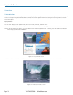
Chapter 2: Overview PiP mode (Picture in Picture): Using this feature, the full-screen display of one of the four video sources is accompanied by one to three small images (thumbnails) of the other video sources that are displayed on the right hand side of the screen. This enables simultaneous monitoring. Figure 2-3. PiP mode screen. Win mode: In Win mode, each video source is displayed in its own separate, detached window. Position each of these windows and adjust their width and height.
Chapter 2: Overview 2.2 Features 2.2.1 DVI and VGA Supports resolutions of up to 1920 x 1200 @ 60 Hz for both DVI and VGA. Any combination of DVI and VGA at all standard resolutions is possible at inputs and output. Analog video input is converted to digital. If an analog display is connected, ServSwitch 4site Flex converts the digital signal to analog at the output. Internally, ServSwitch 4site Flex processes video purely digitally, guaranteeing superior digital image quality. 2.2.
Chapter 2: Overview 2.4 Hardware Description Figures 2-5 and 2-7 show the front and back panels of the ServSwitch 4site Flex. Tables 2-1 and 2-2 describe their components. 2.4.1 Front Panel 3 4 5 6 2 1 7 8 9 10 Figure 2-5. Front panel. Table 2-1. Front-panel components. Component Number in Figure 2-5 Component Description 1 Buttons 1–4 These buttons activate the corresponding channel (computer port).
Chapter 2: Overview Selector Figure 2-6. Selector screen. You can also select the active channel using hotkeys and the arrow keys. The selection window closes once the channel selection timeout period has expired. The channel selection timeout is configured in the OSD under SYSTEM > QUAD MODE. Use the “Time out of channel selection:” menu item to define how long the selector is to be displayed.
Chapter 2: Overview The rear panel of ServSwitch 4site Flex features three audio ports, four input source/computer ports, the console port (KVM), the USB control port, the serial RS-232 control port, four transparent high-speed USB 2.0 device ports, the power connection. Table 2-2. Back-panel components. Component Number in Figure 2-7 Component Description 1 Plug Plug for enclosed power cable. 2 Audio ports Connect external speakers or headphones to the 3.
Chapter 3: Installation 3. Installation To reduce the need for long cables, ServSwitch 4site Flex is best placed as close as possible to its video sources. By default, ServSwitch 4site Flex is delivered as desktop version. Using the rackmount kit (included), it may also be mounted in a 19” rack. Keyboard, monitor, mouse (console) and USB devices are connected to ServSwitch 4site Flex using the corresponding cables (DVI, USB or PS/2).
Chapter 3: Installation NOTE: The maximum cable length for video (DVI/VGA) is up to 64 feet (20 meters). Maximum cable length for USB/PS2 keyboard and mouse is up to 16 feet (5 meters). For greater distances, ServSwitch 4site Flex supports most KVM extenders, video (DVI / VGA) extenders, and USB extenders. 3.3 Connecting Video Sources/Computers 1. Switch off the computer and disconnect the keyboard, monitor and mouse. 2.
Chapter 3: Installation After the speakers have been physically connected to the ServSwitch 4site Flex: • Open the OSD and navigate to COMPUTER > AUDIO • Enable audio output • Select the audio source and adjust the volume. Audio out 1 2 3 Headphones Powered speakers Amplifier Figure 3-4. A variety of device options are available to connect to the ServSwitch 4site Flex for audio output.
Chapter 4: On-Screen Display 4. On-Screen Display 4.1 On-Screen Display (OSD)—Overview Figure 4-1. OSD screen.
Chapter 4: On-Screen Display VIDEO (continued) CROPPING BRIGHTNESS CONTRAST HORIZ POSITION VERT POSITION SCREEN WIDTH PHASE FORMAT Crop the display of video sources Set brightness of analog input signal Set contrast of analog input signal Horizontal screen position Vertical screen position Set screen width of analog input signal Adjust phase of analog input signal Fit input format to screen COMPUTER CHANNEL MAPPING AUDIO NAME 1–4 KEYBOARD MOUSE RESET PS/2 EDID/DDC Assign an input port to a channel
Chapter 4: On-Screen Display The OSD pops up in the center of the screen (on top of the video image). 3 Use a serial or USB connection from a PC to ServSwitch 4site Flex to remotely open the OSD using ConfDev. Figure 4-2. Three ways to open the OSD main menu window. 724-746-5500 | blackbox.
Chapter 4: On-Screen Display 4.3 OSD—Navigation To navigate the OSD, either use the buttons on the front panel or your keyboard. 4.3.1 Navigation with Keyboard To navigate from one field to the next in the OSD menu, use the UP and DOWN arrow keys or TAB/SHIFT-TAB keys. Use the LEFT and RIGHT arrow or + (PLUS) and – (MINUS) keys to change the value in the current field. Press ENTER to select a menu item. Press ESC to return to the previous window (higher menu level) or exit the OSD.
Chapter 4: On-Screen Display 4.4 OSD System 4.4.1 HDCP Status Figure 4-4. System>HDCP Status screen. Use the arrow keys to navigate in the SYSTEM menu to the entry HDCP and press ENTER/SELECT to open the HDCP window. The SYSTEM/HDCP window displays the status of HDCP input and output encoding. HDCP (High-bandwidth Digital Content Protection) is an encoding system used to secure and transmit audio and video. In the upper part of the window, the HDCP status of the four input signals is displayed.
Chapter 4: On-Screen Display The lower portion of the window displays the HDCP status of the output. The first line shows whether the connected monitor supports HDCP. When checked, the next line indicates whether the signal proceeding from the ServSwitch 4site Flex is protected by HDCP. If the output signal is HDCP encoded, the ServSwitch 4site Flex puts out neither analog video signal nor any separate audio signal. 4.4.
Chapter 4: On-Screen Display 4.4.3 Hotmouse Navigate with the arrow keys in the SYSTEM menu to the entry HOTMOUSE and press ENTER/SELECT to open the HOTMOUSE window. Figure 4-6. System>Hotmouse screen. Hotmouse is an exclusive function that comes with ServSwitch 4site Flex. It works with your standard mouse or trackball. To activate Hotmouse operation: 1. Navigate to “Enable Hotmouse” 2. Change the setting to “Yes.” There are two modes of Hotmouse operation: Hotmouse Cursor and Hotmouse Menu.
Chapter 4: On-Screen Display 4.4.4 Quad Mode Use arrow keys to navigate in the SYSTEM menu to the entry QUAD MODE and press ENTER/SELECT to open the QUAD MODE window. Figure 4-7. System>Quad Mode screen. Channel selection timeout defines the period (1 to 30 seconds) after which the selector will close automatically. Default setting is 5 seconds. Figure 4-8. Quad mode. To open the active channel in Quad mode: 1. Press hotkey “Q.” 2.
Chapter 4: On-Screen Display 4.4.5 Win Mode Navigate with the arrow keys in the SYSTEM menu to WIN MODE and press ENTER/SELECT to open the Win mode window. Figure 4-9. System>Win mode screen. Border width: Set the width of the borders, which are drawn around the signals in Win mode. When the border width is zero, no borders are shown. Border colors • Active channel: Press enter/select to open the SELECT COLOR menu and set the color for the active channel.
Chapter 4: On-Screen Display 4.4.6 OSD Position Navigate with the arrow keys in the SYSTEM menu to the entry OSD POSITION and press ENTER/SELECT to open the OSD POSITION window. Figure 4-11. System>OSD Position screen. Use this function to move the OSD window to any position on the screen. 4.4.7 OSD Language Navigate with the arrow keys in the SYSTEM menu to the entry OSD LANGUAGE and press ENTER/SELECT to open the OSD LANGUAGE window. Figure 4-12. System>OSD Language screen.
Chapter 4: On-Screen Display 4.4.8 Security Levels Navigate with the arrow keys in the SYSTEM menu to the entry SECURITY and press ENTER/SELECT to open the SECURITY window. Figure 4-13. System>Enter Password screen. The SECURITY feature allows you to reduce the functional range of ServSwitch 4site Flex. Eight security levels are available. By default, all functions are enabled (security level 0). To change the security level, you must first enter a predefined password.
Chapter 4: On-Screen Display NOTE: Before changing the security level, set the configuration you wish to work with to the higher security level, under MODE > START. This configuration will be maintained when ServSwitch 4site Flex is reset, in case of power failure, or when power is turned off and on again. SECURITY LEVEL 8 Security Level 8 allows you to work only on one channel (computer) in a predefined display mode (Quad, Full-Screen, or PiP mode).
Chapter 4: On-Screen Display SECURITY LEVEL 3 With Security Level 3, you can use the following additional settings in the OSD: SYSTEM OSD LANGUAGE VIDEO BRIGHTNESS/CONTRAST/HORIZ POSITION/VERT POSITION SCREEN WIDTH/PHASE USB DEVICE 1–4 SECURITY LEVEL 2 With Security Level 2, you can use the following additional settings in the OSD: SYSTEM CONSOLE HOTKEY/HOTMOUSE/QUAD MODE KEYBOARD/Touchscreen SECURITY LEVEL 1 With Security Level 1, you have the following additional settings in the OSD: SYSTEM CONSO
Chapter 4: On-Screen Display For example, if you have connected three computers (Channel 1 to 3) to ServSwitch 4site Flex, use the arrow keys to navigate to the number 3 and confirm by pressing ENTER/SELECT. NOTE: To use the “DISABLE CHANNEL” feature, computers/video sources must be connected to ServSwitch 4site Flex in ascending order from Channel 1 to 4. Example in Quad mode: All four channels enabled Three channels enabled Two channels enabled mid-height Figure 4-16. Quad mode example. 4.4.
Chapter 4: On-Screen Display Settings for the connection are: Transfer rate 57600 baud, 8 data bits, no parity, 1 stop bit, no flow control. The two control modes operate as follows: DCP control This mode allows direct control of a single ServSwitch 4site Flex by means of a control device, for example, a computer. The control device can query and change the mode of ServSwitch 4site Flex. ServSwitch 4site Flex responds to each DCP message sent by the control device with a DCP reply.
Chapter 4: On-Screen Display For an introduction to the DEVICE CONTROL PROTOCOL (DCP), see Appendix E. DCP synchronize Use this mode to keep several ServSwitch 4site Flex devices in the same mode. Every change in settings initiated in the first ServSwitch 4site Flex by hotkeys, hotmouse, front-panel buttons, or a controlling device synchronizes the modes of all connected devices via DCP messages. Use special Y cables for the synchronization. Figure 4-20. System>Control, DCP mode Synchronize selected.
Chapter 4: On-Screen Display Example of DCP synchronization ServSwitch 4site Flex 2 and 3 are synchronized with ServSwitch 4site Flex 1. Serial Y Cable Control unit TX ServSwitch 4site Flex 1 RX Console Mouse TX Console Keyboard ServSwitch 4site Flex 2 RX TX RX ServSwitch 4site Flex 3 Figure 4-21. DCP synchronization example. To synchronize, ServSwitch 4site Flex 1 sends every change in settings as a DCP message via the serial Y to the RX input of ServSwitch 4site Flex 2.
Chapter 4: On-Screen Display Table 4-1. Maximum security levels. Page 36 Item Maximum Security Level CONSOLE CHANNEL 6 VIDEO CHANNEL 6 VIDEO LAYOUT 5 PiP LAYOUT 4 PiP HEIGHT 4 PiP OFFSET 4 PiP ZOOM 4 PiP CHANNEL 4 DUAL CHANNELS (L/R) 6 PiP SCAN TIME 4 724-746-5500 | blackbox.
Chapter 5: OSD Mode 5. OSD Mode 5.1 Current Defines the current mode in which the device should run. Figure 5-1. Mode>Current mode screen. Choose from Full-Screen, Quad, PiP, or Win Mode, or Test Pattern. 5.2 START Sets the mode in which the device should boot. Figure 5-2. Mode>Start mode screen. This feature allows you to define the start configuration, i.e.
Chapter 5: OSD Mode See OSD—MODE—CURRENT/START—PiP for details on setting PiP mode to boot. See OSD— MODE—CURRENT/START—WIN for details on setting Win mode to boot. See OSD—MODE —CURRENT/START—TEST PATTERN for details on setting a test pattern to boot. 5.3 PiP Use this section to define the current mode in which the device should run. Figure 5-3. Mode> Current>PiP screen. In the PIP window you can configure PiP size, position, and display mode.
Chapter 5: OSD Mode Figure 5-4. Triple gap. Figure 5-5. Triple no gap. Figure 5-6. Triple tile. 724-746-5500 | blackbox.
Chapter 5: OSD Mode PiP display mode single: One PiP image is displayed. You can choose between different display modes. Figure 5-7. PiP display mode single. Single fixed: One channel is selected to be displayed as permanent PiP image. Only the active channel (full image) can be switched. Press front-panel buttons 1, 2, 3, or 4 to switch the full image. Figure 5-8. Single fixed mode. Single direct: Figure 5-9. Single direct mode. Page 40 724-746-5500 | blackbox.
Chapter 5: OSD Mode One channel is selected to be displayed as permanent full image (active channel). Only the PiP can be switched. Press front-panel buttons 1, 2, 3, or 4 to switch the full image. Single scan: Figure 5-10. Single scan mode. Within a PiP image, when the three other video sources are displayed one after the other, the delay can be set to between one and nine seconds. Figure 5-11. PiP video sources displayed one after the other. 724-746-5500 | blackbox.
Chapter 5: OSD Mode 5.4 Win Mode Navigate with the arrow keys in the MODE menu to the entry WIN. Press ENTER/SELECT to open the WIN MODE window. Figure 5-12. Current mode>WIN mode screen. Select the channel, window mode, position, and window size in the window WIN MODE. The arrows can be used to select the horizontal or vertical position or size of the windows. Activate the checkbox ASPECT RATIO to retain the aspect of the video source. 5.
Chapter 5: OSD Mode We recommend that you use all available test patterns for the test procedure. To exit TEST PATTERN mode, use the OSD, the front-panel buttons (Full, Quad, PiP or Win), or hotkey commands accordingly. Figure 5-14. Test patterns. 724-746-5500 | blackbox.
Chapter 6: OSD Configuration 6. OSD Configuration 6.1 Backup Navigate with the arrow keys in the CONFIGURATION menu to the entry BACKUP. Press ENTER/SELECT to open the BACKUP window. Figure 6-1. Configuration>Backup screen. This function saves the current device settings, including the start mode set in MODE START. Additionally, EDID data from the 4 inputs is also saved. For details on creating an external backup to a file, see the section “Device Configuration Program.” 6.
Chapter 6: OSD Configuration 6.3 Factory Reset/Defaults Navigate with the arrow keys in the CONFIGURATION menu to the Factory Reset Press ENTER/SELECT to open the DEFAULTS window. Figure 6-3. Configuration>Factory Reset screen. Use this function to reset the current settings of ServSwitch 4site Flex to the factory default configuration. All four input EDIDs are also reset to their default values. If necessary, save your current settings before using the DEFAULTS command.
Chapter 6: OSD Configuration FACTORY DEFAULTS (Continued): CONSOLE KEYBOARD TOUCH SCREEN FADE MULTI MONITOR BACKGROUND = English = Mouse emulate right click / = Off = Monitor 1 --> Channel 1; Monitor 2 --> Channel2; Monitor 3 --> Channel 3; Monitor 4 --> Channel4; = Color / 0,0,0 VIDEO = DVI/VGA (all channels) =0 = no cropping = +0 (all channels) = 56 % (all channels) = auto (all channels) = auto (all channels) = +0 (screen-width correction of all channels) = +0 (all channels) = No (all channels) DV
Chapter 7: OSD Console 7. OSD Console 7.1 Video Output Navigate with the arrow keys in the CONSOLE menu to the entry VIDEO OUTPUT. Press ENTER/SELECT to open the VIDEO OUTPUT window. Figure 7-1. Console>Video Output screen. Use the VIDEO OUTPUT menu to choose an output resolution supported by your monitor. Press ENTER/SELECT to enter the selection menu. Use arrow keys to select the desired line in the list shown on the right and press ENTER/SELECT for the new video format.
Chapter 7: OSD Console If the monitor does not offer this data, the ServSwitch 4site Flex sets VGA mode (640x480@60Hz) as the default and activates Sync on Green. Sync on Green can be deactivated on the ServSwitch 4site Flex. Figure 7-3. Video Output/Mode screen. 7.2 Keyboard Navigate with the arrow keys in the CONSOLE menu to the entry KEYBOARD. Press ENTER/SELECT to open the KEYBOARD window.
Chapter 7: OSD Console To control ServSwitch 4site Flex using a touchscreen, connect the touchscreen to the ServSwitch 4site Flex by connecting the VGA or DVI cable from the ServSwitch 4site Flex monitor port to the input of the touchscreen. Connect the USB port of the touchscreen to the ServSwitch 4site Flex console USB port. Please see Chapter 2 for a description of the ServSwitch 4site Flex ports. Figure 7-5. Console>touchscreen window.
Chapter 7: OSD Console Mouse button emulation ServSwitch 4site Flex offers three modes of interpreting the user input as mouse clicks: 1. Mouse: When touching the touchscreen, the mouse button is pressed. When the finger is released from the touchscreen, the mouse button is released. This mode can be used for drag and drop operations. 2. Click on touch: When touching the touchscreen, a mouse click is generated at the position of the touch. 3.
Chapter 7: OSD Console Hotmouse and Hotmouse menu To open the Hotmouse Menu, tap the screen twice, and leave your finger pressed on the touchscreen after the second tap (tap– hold, like a double click without lifting the finger on the second click), until the Hotmouse Menu opens. By clicking outside the Hotmouse Menu, you can open the Hotmouse Cursor to enlarge and reposition PiPs in PiP mode, resize and move windows in Win mode, and switch channels (see description of the Hotmouse function).
Chapter 7: OSD Console 7.5 Multi Monitor Use arrow keys to navigate in the CONSOLE menu to the entry MULTI MONITOR and press ENTER/SELECT to open the MULTI MONITOR window. Figure 7-9. Console>Multi Monitor screen. Multi Monitor is used if computers with multiple video outputs are connected to the ServSwitch 4site Flex but only one keyboard and mouse are operating the computer.
Chapter 7: OSD Console Use the window BACKGROUND to select either a solid color or an image for the background area of the screen on which windows are displayed. NOTE: The background is shown only in Win mode. The default color for the other modes is black. Figure 7-11. Select Color>Console>Background>Image selected. Use BACKGROUND > COLOR to set the color of the background. Enter the desired color in 24-bit color red, green, and blue values. A preview of the color will appear in the field COLOR.
Chapter 7: OSD Console 7.7 EDID (Display of Monitor Data) Use arrow keys to navigate in the CONSOLE menu to the entry EDID and press ENTER/SELECT to open the EDID window. Figure 7-12. Console>EDID>EDID Details screen. Use the EDID command to read and display monitor data (manufacturer, monitor name, serial number, etc.) from the monitor’s EDID memory. If VIDEO OUTPUT is set to “auto,” the ServSwitch 4site Flex uses the optimum output resolution offered by the EDID.
Chapter 8: OSD Video 8. OSD Video 8.1 Input Status (Display Video Formats) Use arrow keys to navigate in the VIDEO menu to the entry INPUT STATUS and press ENTER/SELECT to open the INPUT STATUS window. Figure 8-1. Video>Input Status screen. Resolutions at the four video inputs are shown under INPUT STATUS. Resolution recognition at the four video inputs is automatic. Some analog input resolutions may not correctly be detected.
Chapter 8: OSD Video 8.2 DVI/VGA Use arrow keys to navigate in the VIDEO menu to the entry DVI/VGA and press ENTER/SELECT to open the DVI/VGA window. Figure 8-2. Video>DVI/VGA screen. Go to “Select input signal” and define which video signal (VGA or DVI) is to be displayed. If the setting “DVI/VGA” is selected, ServSwitch 4site Flex will first check the digital input. If there is no signal at this input, the analog signal input will be checked.
Chapter 8: OSD Video Select the degrees to which you would like to rotate your display. Choose from 0, 90, 180, and 270. Once you select the rotation degrees, all the channels are rotated to the same degree. NOTE: Once you choose the degrees, it may take a few seconds for the display to rotate. Rotation limitation at 90° and 270°: If the channels overlap, the monitor display should have a total of lines no higher than 2028.
Chapter 8: OSD Video Use the arrows to increase or decrease the value either in single digits or in increments of 30. Alternatively, you can use the right and left arrows of the keyboard to adjust these values. NOTE: The smallest possible size of each area is 10% of the input signal. 8.5 Brightness/Contrast (with Analog Input Only) Use the arrow keys to navigate in the VIDEO menu to the entry BRIGHTNESS or CONTRAST and press ENTER/SELECT to open the BRIGHTNESS or CONTRAST windows. Figure 8-6.
Chapter 8: OSD Video Figure 8-7. Video>Horizontal/Vertical Position screens. In case the horizontal or vertical position of a computer screen is incorrect, use this feature to adjust the computer screen manually. Use the arrow keys to navigate to the AUTO/MAN field and set to MAN for manual. Use the “+” or “-” keys in the value field to adjust the horizontal position between –63 and +63 and the vertical position between –20 and +20. 8.
Chapter 8: OSD Video Normally, the screen width (number of horizontal pixels) is defined by the VESA standard. If the screen appears blurred, change this setting to improve screen quality. 8.8 Phase (with Analog Input Only) Use the arrow keys to navigate in the VIDEO menu to the entry PHASE and press ENTER/SELECT to open the PHASE window. Figure 8-9. Video>Phase screen. Incorrect phase (sampling time of pixel color value) may result in blurring, bad contrast, or poor legibility.
Chapter 8: OSD Video By default, “fit to screen” is disabled to display each source in its native aspect ratio in display modes (Quad, PiP, Full) of ServSwitch 4site Flex. Figure 8-11. Wide-screen monitor in Quad mode. PiP mode for wide-screen monitors If you use a wide-screen monitor (for example with an aspect ratio of 16:10) and the active channel does not have a wide-screen aspect ratio (e.g. 4:3), PiPs are placed aside the full image of the active channel in the black bar on the right side.
Chapter 8: OSD Video Full-screen is positioned on the left-hand side in PiP mode Full-screen mode Figure 8-12. PiP mode for wide-screen monitors. Page 62 724-746-5500 | blackbox.
Chapter 9: OSD Computer 9. OSD Computer 9.1 Channel Mapping Use the arrow keys to navigate in the COMPUTER menu to the entry CHANNEL MAPPING and press ENTER/SELECT to open the CHANNEL MAPPING window. Figure 9-1. Computer>Channel Mapping screen. In the CHANNEL MAPPING menu, you can change the assignment between physical input ports and logical channels. This can be useful, for instance, if computer needs to be shown on another position on the quad screen without having to swap the connectors at the inputs.
Chapter 9: OSD Computer 9.2 Audio Use the arrow keys to navigate in the COMPUTER menu to the entry AUDIO and press ENTER/SELECT to open the AUDIO window. Figure 9-2. Computer>Audio>Volume screens. “Enable audio output:” To enable or disable the audio output, activate or deactivate the checkbox “Enable audio output.” Selecting audio source: Select the audio source from the list. To ensure that the audio source is the computer being currently operated, select ”active channel” from the list.
Chapter 9: OSD Computer NOTE: You can also open this window with the hotkeys HK + -/+. 9.3 Name 1–4 Use the arrow keys to navigate in the COMPUTER menu to the entry NAME 1-4 and press ENTER/SELECT to open the NAME 1-4 window. Figure 9-3. Computer>Name 1–4>Change Name screens. Use the section NAME to assign a name to each of the four windows displayed when HOTMOUSE is in use. Move the cursor in the edit window using arrows on your keyboard. Press ENTER/SELECT to choose a letter.
Chapter 9: OSD Computer 9.4 Keyboard Use arrow keys to navigate in the COMPUTER menu to the entry KEYBOARD and press ENTER/SELECT to open the KEYBOARD window. Figure 9-4. Computer>Keyboard screen. Use this display feature to identify which keyboard type (USB, PC1, PC2 or PC3) has been recognized at which computer port. 9.5 Mouse Use the arrow keys to navigate in COMPUTER menu to the MOUSE line and press ENTER/SELECT to open the MOUSE window. Figure 9-5. Computer>Mouse screen.
Chapter 9: OSD Computer USB—mouse positioning For USB ports, you may specify absolute or relative mouse positioning. Choose absolute mouse positioning if a device is connected to the console that supports absolute coordinates, such as graphic trays, screen pads, or KVM extenders. 9.6 Reset PS/2 Use the arrow keys to navigate in the COMPUTER menu to the entry RESET PS/2 and press ENTER/SELECT to open the RESET PS/2 window. Figure 9-6. Computer>Reset PS/2 screen.
Chapter 9: OSD Computer Figure 9-8. Computer>EDID>DDC/Mode screen. Use the arrow keys to select the channel EDID information. Press ENTER/SELECT to open the window with detailed settings for this EDID. Select a video mode for the channel using the arrow keys. Press ENTER/SELECT to confirm the selection. Two freely selectable video modes can be programmed in the input EDID visible to the connected computer at the input port. We recommend programming the preferred video modes for the connected signal source.
Chapter 9: OSD Computer Figure 9-9. EDID>EDID/DDC screen. ServSwitch 4site Flex also uses these entries to distinguish between confusable analog input video signals.
Chapter 9: OSD Computer Alternatively, the EDID data of the connected display can be used. To do this, navigate to SAME AS DISPLAY EDID and press ENTER/SELECT. • SAME AS DISPLAY EDID: Write the contents of the display EDID to the current input EDID. Press ENTER/SELECT to start the selected write option and wait until “successful” is displayed in the bottom status line. At this point, the EDID data can be written to one or all of the four channels.
Chapter 10: OSD—USB Device 1–4 10. OSD—USB Device 1–4 10.1 USB Port Status ServSwitch 4site Flex supports and switches transparent USB 2.0 devices such as printer, camera, 3D mouse, finger printer, and external memory. (Example: Connect a memory stick to copy data from one computer to the stick, and from the stick to another computer connected to ServSwitch 4site Flex: Data can be copied between computers without being networked.
Chapter 10: OSD—USB Device 1–4 OFF: Port is not switched to a computer. A USB device may be connected, but it is not switched to a computer. Computer (1-4): Port is switched to one of the computers. To change port and switch settings, use the arrow keys to select one of the four USB ports and open its submenu by pressing ENTER/SELECT. Device 1 switch to: Off by default.
Chapter 10: OSD—USB Device 1–4 10.3 Change Device Name In the “USB DEVICE/USB DEVICE” menu, choose “Change device name” and press ENTER/SELECT to change the name of the connected USB device. Use the keyboard to rename the USB device or use the front-panel buttons (as described in the OSD). Exit the menu. The new name will automatically be saved and displayed in the other menus. Figure 10-4. USB Device>Change Name screen.
Chapter 11: OSD Help 11. OSD Help Use the arrow keys to navigate in the HELP menu to the desired line and press ENTER/SELECT to open the corresponding window. Figure 11-1. Help>About/Details. HELP > ABOUT displays the current revision levels hardware and firmware. Figure 11-2. Help>Hotkey. HELP > HOTKEY provides a guide to hotkey shortcuts. Page 74 724-746-5500 | blackbox.
Chapter 12: Hotmouse 12. Hotmouse Hotmouse is an exclusive function offered by ServSwitch 4site Flex. It works with your standard mouse or trackball and touchscreens. Similar to using hotkeys on your keyboard, Hotmouse is a quick and comfortable way to operate ServSwitch 4site Flex simply with your standard mouse, trackball, or touchscreen. No software or additional hardware is required.
Chapter 12: Hotmouse 12.2 Hotmouse Cursor in Full-Screen Mode/Quad Mode When you activate the hotmouse cursor in Full-Screen mode, PiP images of the other channels are temporarily displayed to allow you to switch to another channel. Switching to another full-screen channel Activate hotmouse cursor. Move the hotmouse cursor over the PiP image of the channel that you want to activate and click the left mouse button. Channel 1 is active Channel 3 is selected Channel 3 is active Figure 12-3.
Chapter 12: Hotmouse 12.3 Hotmouse Cursor in PiP Mode Change active channel Enable Hotmouse Cursor. Move the Hotmouse Cursor to the PiP image of the channel you want to activate and press the left mouse button. NOTE: When the hotmouse cursor moves over a PiP image, its appearance changes (arrows, channel number). Channel 2 is active Channel 3 is selected Channel 3 is active Figure 12-5. Example: Switch from Channel 2 to Channel 3. Vertical positioning of PiP images Activate Hotmouse Cursor.
Chapter 12: Hotmouse Hold left mouse button Figure 12-7. Scaling PiP images up. Hold left mouse button Figure 12-8. Scaling PiP images down. 12.4 Hotmouse Cursor in Win Mode Change active channel Enable Hotmouse Cursor. Move the Hotmouse Cursor to the window of the channel you want to activate and press the left mouse button. NOTE: When the hotmouse cursor moves over a window, its appearance changes (arrows, channel number). To close the hotmouse cursor, left double-click or use hotkey +M in Win mode.
Chapter 12: Hotmouse NOTE: As soon as the hotmouse cursor moves over a window, its appearance changes (arrows pointing vertically or horizontally). Channel 2 needs to be resized. The edge of Channel 2 is selected for vertical rezing. Channel 2 is resized. Figure 12-10. Example: Resizing windows. Repositioning windows Enable Hotmouse Cursor. Move the Hotmouse Cursor to the window that you want to move and press the left mouse button.
Chapter 12: Hotmouse Operating The Hotmouse Menu allows you to carry out switching operations and to enter PiP settings by mouse click (left mouse button). Click Help on the Hotmouse Menu for information on the individual symbols. Figure 12-12. Hotmouse menu in PiP mode. Hotmouse Menu in PiP-mode: Click with the left mouse button on the arrow symbols to either increase or decrease the values in question. Clicking on the outer arrow symbols sets the minimum or maximum value.
Chapter 12: Hotmouse 12.5.2 Mode—Quad, Full, PiP, or Win The individual modes can be set as follows: Hotmouse Menu—QUAD MODE Use the mouse to navigate to a channel in the Hotmouse Menu and click the left mouse button to activate it. You can also switch to a different mode with the left mouse button. Figure 12-14. Hotmouse menu in Quad mode. Figure 12-15. Quad mode. Hotmouse Menu—FULLSCREEN MODE Use the mouse to navigate to a channel in the Hotmouse Menu and click the left mouse button to activate it.
Chapter 12: Hotmouse Figure 12-17. Full-Screen mode. Hotmouse menu—PIP mode Use the mouse to navigate to a channel in the Hotmouse Menu and click the left mouse button to activate it. Change the position and size of PiP images, and PiP zoom. Change PiP mode (triple/triple gap/single fixed/single direct/single scan) and scan time. Triple gap: PiP images are displayed with a gap in place of the active channel. Figure 12-18. Triple gap. Triple no gap: PiP images are displayed without a gap. Figure 12-19.
Chapter 12: Hotmouse Triple tile: The size of the main image and the PiP images is optimized so that the main image and the PiP images are shown as large as possible without overlapping. Figure 12-20. Triple tile. Single fixed: One selected PiP image is permanently displayed. Single direct: Press the front panel buttons 1, 2, 3, or 4 to directly select the PiP channel you want. Figure 12-21. Single fixed and direct PiP image screens. 724-746-5500 | blackbox.
Chapter 12: Hotmouse . Figure 12-22. Single scan: Cycles through the PiP images at a set interval. Win mode Use the section “Mode” in the hotmouse menu in WIN mode to save the position of your channel windows. Four different configuration sets can be saved under win1, win2, win3 or win4. 1. Enter Win mode. 2. Position and/or resize your channel windows as desired. 3. Activate the hotmouse menu. 4. Select one of the win slots. 5. Click “Save” at the bottom of the hotmouse menu. Figure 12-23.
Chapter 13: Troubleshooting 13. Troubleshooting 13.1 Contacting Black Box If you determine that your ServSwitch 4site Flex is malfunctioning, do not attempt to alter or repair the unit. It contains no userserviceable parts. Contact Black Box Technical Support at 724-746-5500 or info@blackbox.com. Before you do, make a record of the history of the problem.
Appendix A: Keyboard Commands Appendix A. Keyboard Commands ServSwitch 4site Flex supports two types of hotkeys: “multiple keys” and “double click.” By default, ServSwitch 4site Flex is set to “multiple keys.” Use the OSD menu to choose the hotkey type and keys. Multiple keys: Press multiple keys plus command key. COMMAND = and together. The following hotkeys are available for selection: Ctrl, Shift, Alt, and Win.
Appendix A: Keyboard Commands Open USB device switch menu: + = Open USB device/Port 1 switch menu.
Appendix B: Device Configuration Program Appendix B. Device Configuration Program Installation of Device Configuration Program (CONFDEV) The Device Configuration Program enables you to remotely operate the OSD of ServSwitch 4site Flex on an external Windows computer via serial connection. To install the device configuration software CONFDEV, you need: • A Windows computer with a free USB or RS 232 COM-port • Your ServSwitch 4site Flex • The installation CD containing the confdevEn.
Appendix B: Device Configuration Program Settings Click the “device configuration” button to open the SETTINGS window. It enables you to set the font size for the OSD window, log parameters, and the COM port ServSwitch 4site Flex is connected to. Figure B-3. Settings screen. Remote OSD operation Click the green arrow computer. to open the On Screen Display (OSD) of ServSwitch 4site Flex remotely on your external Windows The main OSD menu is open and ready for navigation.
Appendix B: Device Configuration Program Figure B-4. Navigation screen. Uploading a background image A background image can be uploaded to the ServSwitch 4site Flex and will be displayed behind windows when in Win Mode. To upload an image to the ServSwitch 4site Flex, use the ConfDev menu DEVICE >LOAD BACKGROUND IMAGE. IMPORTANT: Only 256 color bitmaps are supported for background images. The file used should have a maximum size of 2 MB. The maximum resolution will be that of the connected monitor.
Appendix B: Device Configuration Program Figure B-5. Uploading a background image to the ServSwitch 4Site Flex. A 256-color bitmap is uploaded from the user PC to ServSwitch 4Site Flex using the ConfDev utility. Storing a configuration ConfDev can also be used to store device configurations to a file on your PC. Open the ConfDev menu DEVICE > STORE CONFIGURATION. The Save As dialog will appear and you can save the configuration to the desired location. 724-746-5500 | blackbox.
Appendix B: Device Configuration Program Figure B-6. Storing a configuration. Loading a configuration ConfDev can be used to load device configurations from a file on your PC. Open the ConfDev menu DEVICE > LOAD CONFIGURATION. The Open dialog will appear from which you can select the configuration file to be loaded. Figure B-7. Loading a configuration. Page 92 724-746-5500 | blackbox.
Appendix C: Update ServSwitch 4site Flex Firmware Appendix C: Update ServSwitch 4site Flex Firmware To execute a firmware update, you need: • a computer with serial or USB port • the enclosed “serial cable” (RJ-45-DB9 adapter + RJ-45 CAT5 cable) or a USB cable (USB-A/USB-B) • the current executable firmware file Follow these steps: 1a. Use the serial cable to connect the COM port of your computer to the RS-232 port on ServSwitch 4site Flex. OR 1b.
Appendix C: Update ServSwitch 4site Flex Firmware Figure C-2. Update firmware screen. 2. Start the executable firmware file. 3. Set the desired COM port. 4. Press “Update.” LEDs 1–4 on the front panel of the ServSwitch 4site Flex flash (blue) during the update. Additionally, the upgrade process is indicated by an OSD window on your remote computer. Figure C-3. OSD update screen. After successful update, ServSwitch 4site Flex restarts without changing configuration. Page 94 724-746-5500 | blackbox.
Appendix D: Serial Cable Appendix D. Serial Cable For serial remote control, ServSwitch 4site Flex requires a special adapter to connect a CAT5 cable to the serial RJ-45 port at the rear panel of ServSwitch 4site Flex. This adapter connects to your external serial control device (for example, computer). You can connect any CAT5 cable to the adapter. The other end of the CAT5 cable connects to the RJ-45 port of ServSwitch 4site Flex.
Appendix E: DCP-XML Remote Control Appendix E. DCP-XML Remote Control DCP-XML permits remote control of ServSwitch 4site Flex by a computer or other devices using the RS-232 serial port of ServSwitch 4site Flex. To connect to this port, use the “serial cable” (RJ-45-DB9 adapter + standard RJ45 CAT5 cable). Device Control Protocol (DCP) is an XML-based protocol. Using DCP, you can query and change all important settings of the ServSwitch 4site Flex. For a general description of XML, go to at http://www.w3.
Appendix F: Supported Touchscreen Controller Appendix F.
Appendix G: Supported Video Input Appendix G. Supported Video Input Table G-1. Video input (display video formats). Mode Resolution Sync.
Appendix G: Supported Video Input Table G-1 (Continued). Video input (display video formats). Mode Resolution Sync.
Appendix H: Supported Video Output Appendix H. Supported Video Output Table H-1. Video output (display video formats).
Appendix H: Supported Video Output Table H-1 (Continued). Video output (display video formats). Mode Horizontal Vertical Hz WUXGAr 1920 1200 60 HDTVp 1280 720 50 HDTVp 1920 1080 24 HDTVp 1920 1080 50 HDTVp 1920 1080 60 NOTE: When set to auto (by default), ServSwitch 4site Flex reads the EDID of the monitor connected and automatically supports its resolution. 724-746-5500 | blackbox.
Appendix I: Cascading Appendix I. Cascading Cascading multiple ServSwitch 4site Flex units—more than 4 video sources on a single display: ServSwitch 4site Flex can be cascaded to display more than 4 video sources simultaneously on a single display. In this master-slave-system, any ServSwitch 4site Flex can be used as master or slave. It is the same hardware. One ServSwitch 4site Flex is used as master unit.
NOTES 724-746-5500 | blackbox.
Black Box Tech Support: FREE! Live. 24/7. Tech support the way it should be. Great tech support is just 30 seconds away at 724-746-5500 or blackbox.com. About Black Box Black Box provides an extensive range of networking and infrastructure products. You’ll find everything from cabinets and racks and power and surge protection products to media converters and Ethernet switches all supported by free, live 24/7 Tech Support available in 30 seconds or less. © Copyright 2012. Black Box Corporation.