
Server User Manual

Chapter 2 Installation
INSTALLATION
Introduction
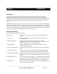
This chapter describes how to install the console server hardware and connect it to controlled devices.
To avoid physical and electrical hazards please read Appendix C on Safety.
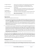
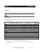
2.1 Models
There are multiple console server models, each with a different number of network and serial ports or
power supply configurations:
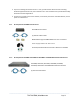
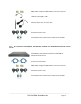
The next sections show the components shipped with each of these models.
Unpack your kit and verify you have all the parts shown above, and that they all appear in good
working order.
Serial
Ports
USB
Ports
Network
Ports
Console
Port
Modem
RJ
Pinout
Power
Memory
(flash/RAM)
LES1508A
8
2
2
1
-
02
Ext AC/DC
16/64MB, 4GB
LES1448A
48
2
2
1
Internal CDMA
01
Dual AC
16/64MB, 16GB
LES1432A
32
2
2
1
Internal CDMA
01
Dual AC
16/64MB, 16GB
LES1416A
16
2
2
1
Internal CDMA
01
Dual AC
16/64MB, 16GB
LES1408A
8
2
2
1
Internal CDMA
01
Dual AC
16/64MB, 16GB
LES1348A
48
2
2
1
Internal GSM
01
Dual AC
16/64MB, 16GB
LES1332A
32
2
2
1
Internal GSM
01
Dual AC
16/64MB, 16GB
LES1316A
16
2
2
1
Internal GSM
01
Dual AC
16/64MB, 16GB
LES1308A
8
2
2
1
Internal GSM
01
Dual AC
16/64MB, 16GB
LES1248A-R2
48
3
2
1
Internal V.92
01
Dual AC
16/64MB, 16GB
LES1232A
32
3
2
1
Internal V.92
01
Dual AC
16/64MB, 16GB
LES1216A-R2
16
3
2
1
Internal V.92
01
Dual AC
16/64MB, 16GB
LES1208A-R2
8
3
2
1
Internal V.92
01
Dual AC
16/64MB, 16GB
LES1148A
48
-
1
1
-
00
Single AC
16/64MB
LES1132A
32
-
1
1
-
00
Single AC
16/64MB
LES1116A
16
-
1
1
-
00
Single AC
16/64MB
LES1108A
8
-
1
1
-
00
Ext AC/DC
8/16MB
_____________________________________________________________________
724-746-5500 | blackbox.com Page 18