
Electronic Accessory User Manual


Page 7
724-746-5500 | blackbox.com
3) VERIFY OPERATION
Once the module has been installed and congured per steps 1 and 2, verify the module is
operational by viewing the LED indicators.
Legend OFF State Color ON/Blinking State
Pwr Off – No power. Green Green – Power On
P1 Lk
Off – No Transceiver detected
or no ber link.
Green Green Solid – Fiber link (signal detect).
Amber
Amber Blinking (1Hz) – Port is disabled due to
installed transceiver drawing more current than
allowed.
P1 Stat
Off – Transceiver does not
support digital diagnostic or
no transceiver installed.
Green
Green Solid – Transceiver supports digital
diagnostic and no DDMI Alarm Detected.
Amber
Amber Solid – Transceiver supports digital
diagnostic and DDMI alarm detected.
Amber Blinking (1Hz) – Port is disabled due to
installed transceiver drawing more current than
allowed.
P1 LB
Off – Port loopback mode not
enabled or congured.
Green
Green Solid – Port set to Loopback mode and port
in loopback.
Green Blinking (1 Hz) – Port responding to BIST
activation with valid BIST response.
Green Blinking (5 Hz) – Port initiating BIST and
receiving valid BIST response.
Amber
Amber Solid – Port set to loopback mode, but XFP
does not support loopback
Amber Blinking (5 Hz) – Port initiating BIST and not
receiving valid BIST response
P2 Lk
Off – No Transceiver detected
or no ber link.
Green Green Solid – Fiber link
Amber
Amber Blinking (1Hz) – Port is disabled due to
installed transceiver drawing more current than
allowed.
P2 SR
Off - Short Reach function is
disabled.
Green Green Solid – Short Reach function is enabled.
P2 LB
Off – Port loopback mode not
enabled or congured.
Green
Green Solid – Port set to Loopback mode and port
in loopback.
Amber
Amber Solid – Port set to loopback mode, but
loopback is not supported.
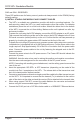
Figure 4: LED Indicators
Installation Procedure