LMC5206A LM5236A
FCC and IC RFI Statements FCC and Industry Canada RF Interference Statements Class A Digital Device. This equipment generates, uses, and can radiate radiofrequency energy, and if not installed and used properly, that is, in strict accordance with the manufacturer’s instructions, may cause interference to radio communication.
FCC and IC RFI Statements This digital apparatus does not exceed the Class B limits for radio noise emission from digital apparatus set out in the Radio Interference Regulation of Industry Canada. Product Description 20-Slot Rackmount Chassis 6-Slot Chassis Rackmount/Desktop 3-Slot Desktop Chassis LMC5207A-R3 Version Dual Dual ACDC AC Dual DC Dual AC 2AC DC 2DC ACDC FCC Class A FCC Class B AC DC AC DC 724-746-5500 | blackbox.
NOM Statement Normas Oficiales Mexicanas (NOM) Electrical Safety Statement Instrucciones de Seguridad 1. Todas las instrucciones de seguridad y operación deberán ser leídas antes de que el aparato eléctrico sea operado. 2. Las instrucciones de seguridad y operación deberán ser guardadas para referencia futura. 3. Todas las advertencias en el aparato eléctrico y en sus instrucciones de operación deben ser respetadas. 4. Todas las instrucciones de operación y uso deben ser seguidas. 5.
NOM Statement 17. Cuidado debe ser tomado de tal manera que objecos líquidos no sean derramados sobre la cubierta u orificios de ventilación. 18. Servicio por personal calificado deberá ser provisto cuando: a. El cable de poder o el contacto ha sido dañado; u b. Objectos han caído o líquido ha sido derramado dentro del aparato; o c. El aparato ha sido expuesto a la lluvia; o d. El aparato parece no operar normalmente o muestra un cambio en su desempeño; o e.
Certifications Certifications UL/CUL: Listed to Safety of Information Technology Equipment, including Electrical Business Equipment. Class 1 Laser product, Luokan 1 Laserlaite, Laser Klasse 1, Appareil A’Laser de Classe 1 European Directive 2002/96/EC (WEEE) requires that any equipment that bears this symbol on product or packaging must not be disposed of with unsorted municipal waste. This symbol indicates that the equipment should be disposed of separately from regular household waste.
Table of Contents Table of Contents Part Numbers ................................................................................................... 8 1. Specifications .......................................................................................... 10 1.1 20-Slot Rackmount Chassis Specifications ............................................ 10 1.2 6-Slot Rackmount/Desktop Chassis Specifications ................................ 10 1.3 3-Slot Desktop Chassis Specifications ..........................
Part Numbers Part Numbers 20-Slot Rackmount Chassis Part Number Description LMC5200A SNMP Management Module LMC5207A-R3 20-Slot, w/Dual AC Power LMC5208A-R3 20-Slot, w/Dual DC Power LMC5227A-R2 20-Slot, W/Fixed Single AC Power LMC5228A 20-Slot, w/ACDC Power Back Up, Spares, Sold Separately Part Number Description LMC5210A Power Supply Module for LMC5207A-R2 LMC5210A-R3 Power S.
Part Numbers Back Up, Spares, Sold Separately Part Number Description LMC5200A SNMP Management Module includes Black Box and View² LMC5238A 19 inch Rackmount shelf and screws LMC5207A-R3 724-746-5500 | blackbox.
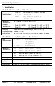
Chapter 1: Specifications 1. Specifications 1.1 20-Slot Rackmount Chassis Specifications Input Specifications: Operating Temperature: Storage Temperature: Dual AC Dual DC ACDC 100 to 240V AC, 50/60Hz, 3.5/1.5A -48V DC, 5A 100 to 240V AC, 50/60HZ, 2A -48V DC, 4.4A 0° C to +50° C (+32° F to +122° F) Dual AC & ACDC Dual DC -20° C to +80° C (-4° F to +176° F) -20° C to +60° C (-4° F to +140° F) Humidity: 20 to 90% (non-condensing at +40° C [+104° F]) Shipping Weight 25 lbs (11.3 kg) Dimensions 5.
Chapter 1: Specifications 1.3 3-Slot Desktop Chassis Specifications Input Specifications: Operating Temperature: Storage Temperature: AC DC 100 to 240V AC, 50/60Hz, 0.75A 35V DC to 75V DC Max, 1.6A AC DC 0° C to +50° C (+32° F to 122° F) -40° C to +50° C (-40° F to +122° F) AC DC -40° C to +85° C (-40° F to +185° F) -55° C to +125° C (-67° F to +257° F) Humidity: 5 - 95% (non-condensing); 0-10,000 ft. altitude Shipping Weight 5 lbs (2.3 kg) Dimensions 1.73”H x 7.45”W x 8.74”D (4.
Chapter 2: Overview: High-Density Media Converter System II 2. Overview: About the High-Density Media Converter System II 2.1 The 20-Slot Rackmount Chassis The 20-Slot Rackmount Chassis series is a modular chassis platform designed for use with Black Box Simple Network Management Protocol (SNMP) manageable series of modules.
Chapter 2: Overview 2.3 The 3-Slot Desktop Chassis The 3-Slot Desktop Chassis series is a modular chassis platform designed for use with Black Box Simple Network Management Protocol (SNMP) manageable series of modules. The 3-Slot Desktop Chassis is a 1U high, rackmountable chassis that can use redundant power supply modules, and supports a SNMP Management Module.
Chapter 3: Install the High-Density Media Converter System II 3. Install the High-Density Media Converter System II 3.1 Installing the 20-Slot Rackmount Chassis Install the chassis first before installing any modules into a 20-Slot Rackmount Chassis. When installing the chassis, be sure to observe the following precautions to prevent electrical or mechanical damage: 1. Protect the chassis from exposure to sunlight and electrical or magnetic fields. 2.
Chapter 3: Install the High-Density Media Converter System II 3. A suitable listed circuit breaker shall be provided in the building installation as the unit's disconnect device. The branch circuit rating (i.e. minimum 15A listed circuit breaker, etc.). DC Power Supply Module Wiring Instructions The following diagram shows the wiring configuration for a -48 VDC power supply module for the 20-Slot Rackmount Chassis 2DC and ACDC. NOTE The chassis is protected against incorrect wiring configurations.
Chapter 3: Install the High-Density Media Converter System II 3.1.3 Replacing Power Supply Modules User-Replaceable Power Supply Modules While power supply modules are redundant, you should promptly replace failed power supply modules to maintain network integrity and prevent data loss. To replace a power supply module: 1. Disconnect the power source from the power supply module. 2. Remove the screws of the retainer plate (on some AC modules). 3.
Chapter 3: Install the High-Density Media Converter System II Dual DC power supplies (LMC5241A) on LMC5208A-R3 Chassis NOTE You can mix AC and DC power supply modules, because they are the same size. AC, DC power supplies (one of each), on LMC5228A Chassis NOTE For LMC5228A 20-Slot Rackmount Chassis, all models in that model number series can support Dual AC, Dual DC or ACDC. The power supply modules for that model number series are interchangeable. 3.
Chapter 3: Install the High-Density Media Converter System II To install a 6-Slot Rackmount/Desktop Chassis: 1. Have four #10 screws and four clip nuts available (hardware may vary depending on rack type). The rest of the hardware is supplied with the unit. 2. Locate a suitable location in the rack for installation and secure the clip-nuts onto the mounting rails. Use screws to attach the chassis to the rack. 3. Plug the chassis into a reliable, filtered power source. 4.
Chapter 3: Install the High-Density Media Converter System II To install a second power supply: 1. Remove the filler tray. 2. Slide the power supply module into the chassis and click into place. 3. Attach the power cord. To remove a power supply module: 1. Disconnect the power source from the power supply. 2. Move the Power Supply Release switch toward the right and hold while grasping the power supply module by the silver handle. 3. Slide out of the chassis. (Power supply modules are hot-swappable.) 4.
Chapter 3: Install the High-Density Media Converter System II 3.3 Installing the 3-Slot Desktop Chassis Install the chassis first before installing any modules into a 3-Slot Desktop Chassis. When installing the chassis, be sure to observe the following precautions to prevent electrical or mechanical damage: 1. Stay within the chassis’ power rating to prevent overload of supply circuits or damage to any overcurrent protection and supply wiring. 2.
Chapter 3: Install the High-Density Media Converter System II 3.3.1 DC Power Wiring, Replacing Power Supply and Fans DC Power Supply Wiring Instructions The following image shows the wiring configuration for a 48-VDC power supply in a negative ground system application. For positive ground system applications remove the chassis ground shorting jumper and connect it between the positive terminal and the chassis ground terminal.
Chapter 3: Install the High-Density Media Converter System II The red Alarm Reset Button also functions as a Fan Test button. To verify fan functionality, hold the button down for several seconds; the fans should engage. The fans will turn off when the button is released. 3.3.2 Installing Management and Application Modules SNMP Management Modules include two twisted pair ports, one for management and one reserved for future use.
Chapter 4: Operation 4. Operation 4.1 The 20-Slot Rackmount Chassis 4.1.1 Alarm Reset, Last Gasp, and Temperature Gauge The 20-Slot Rackmount Chassis series supports power supply modules, so that worn parts can be replaced without having to send an entire unit in for repair. User-Replaceable Power Supply Modules Reset Alarm Button When one power supply module malfunctions, an audible alarm sounds indicating the loss of the power module.
Chapter 4: Operation board from re-configuring the application module settings (e.g., the status of features such as LinkLoss, FiberAlert, Force mode, etc.) made via SNMP on any previous Management Modules. NOTE Leave this switch in the NORMAL position during day-to-day operation; the LOCKED position should only be used when changing the SNMP management board. The SNMP Management Module can be removed and replaced as necessary.
Chapter 4: Operation immediately. (LEDs on the Management Module and the power supply itself also indicate power supply failures.) After stopping the alarm, remove the power supply and replace the power supply module.
Chapter 4: Operation 4.2.3 SNMP Management Module LEDs The SNMP Management Module features several LEDs. The LED functions are: LNK/ACT Glows green when a link is established on port. Blinks green when data activity occurs. FDX/COL Glows yellow when port is in Full-Duplex mode. Blinks yellow when port is operating in Half-Duplex mode and collisions occur. TEMP Glows yellow when temperature of unit surpasses a user-defined level. PS Glows yellow when one module malfunctions.
Chapter 4: Operation 4.3.2 SNMP Write Lock The SNMP Write Lock switch is located on the back of the 3-Slot Desktop Chassis. The SNMP Write Lock switch prevents a new management board from re-configuring the application module settings (e.g., the status of features such as LinkLoss, FiberAlert, Force mode, etc.) made via SNMP on any previous Management Modules.
Chapter 5: Contacting Black Box 5. Contacting Black Box Black Box Customer Service Order toll-free in the U.S.: Call 877-877-BBOX (outside U.S. call 724-746-5500) Free technical support, 24 hours a day, 7 days a week. Call: 724-746-5500 or Fax: 724-746-0746 Mail order: Black Box Corporation 1000 Park Drive, Lawrence, PA 15055-1018 Web site: www.blackbox.com E-mail: info@blackbox.com WARNING Disconnect all power supplies before servicing. Page 28 724-746-5500 | blackbox.
Chapter 6: Fiber Optic Cleaning Guidelines 6. Fiber Optic Cleaning Guidelines Fiber Optic transmitters and receivers are extremely susceptible to contamination by particles of dirt or dust, which can obstruct the optic path and cause performance degradation. Good system performance requires clean optics and connector ferrules. 1.
Chapter 7: Electrostatic Discharge Precautions 7. Electrostatic Discharge Precautions Electrostatic discharge (ESD) can cause damage to any product, add-in modules or stand alone units, containing electronic components. Always observe the following precautions when installing or handling these kinds of products. 1. Do not remove unit from its protective packaging until ready to install. 2. Wear an ESD wrist grounding strap before handling any module or component.
NOTES LMC5207A-R3 724-746-5500 | blackbox.
LMC5207A-R3, Rev.