
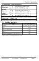
Specifications


Chapter 3: Install the High-Density Media Converter System II
Page 14
724-746-5500 | blackbox.com
LMC5207A-R3
3. Install the High-Density Media Converter System II
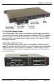
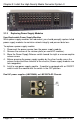
3.1 Installing the 20-Slot Rackmount Chassis
Install the chassis first before installing any modules into a 20-Slot Rackmount
Chassis. When installing the chassis, be sure to observe the following
precautions to prevent electrical or mechanical damage:
1. Protect the chassis from exposure to sunlight and electrical or magnetic
fields.
2. Make sure that the equipment rack remains stable, even with the addition of
the chassis and its associated cabling.
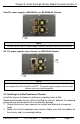
To install the 20-Slot Rackmount chassis:
1. Have four #10 screws and four clip nuts available (hardware may vary
depending on rack type). The rest of the hardware is supplied with the unit.
2. Locate a suitable location in the rack for installation and secure the clip-nuts
onto the mounting rails. Use screws to attach the chassis to the rack.
3. Plug the chassis into a reliable, filtered power source.
4. Elevated Operating Ambient - If installed in a closed or multi-unit rack
assembly, the operating ambient temperature of the rack environment may
be greater than room ambient. Install the equipment in an environment that is
compatible with the maximum ambient temperature (Tma) specified by Black
Box.
5. Reduced Air Flow - Install the equipment in a rack so that the amount of air
flow required for safe operation of the equipment is not compromised.
6. Mechanical Loading - Mount the equipment in the rack so that a hazardous
condition does not occur because of uneven mechanical loading.
7. Circuit Overloading - Consideration should be given to the connection of the
equipment to the supply circuit and the effect that overloading of the circuits
might have on over-current protection and supply wiring.
8. Reliable Grounding - Maintain reliable grounding of rackmounted equipment.
Give particular attention to supply connections other than direct connections
to the branch circuit (e.g., use of power strips).
9. All AC and DC versions are intended for use in a Restricted Access Location
(RAL).
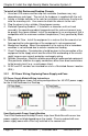
3.1.1 Wiring Instruction Guidelines for DC Module in 2DC and ACDC
1. Connection of a suitable grounding conductor to the grounding terminal at
each power supply module (a minimum 14AWG copper conductor should be
suitable based on a 15A circuit breaker requirement).
2. Connection of suitable supply wiring to the plus and minus terminals at each
power supply module (a minimum 14AWG copper conductors is considered
suitable based on the 11A input maximum). The input terminal block at the
power supply module is suitable for 22-14 AWG copper wire.