LMC5207A-R2 LMC5208A-R2 LMC5227A-R2 LMC5228A LMC5203A LMC5204A LMC5205A LMC5234A LMC5206A LMC5235A LMC5233A LMC5236A LMC5227A High-Density Media Converter System II Choose from a wide variety of chassis and modules to build a powerful media-converter solution. Customer Support Information Order toll-free in the U.S.: Call 877-877-BBOX (outside U.S.
FCC and Industry Canada RF Interference Statements Class A This equipment generates, uses, and can radiate radio-frequency energy, and if not installed and used properly, that is, in strict accordance with the manufacturer’s instructions, may cause interference to radio communication.
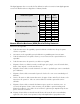
This digital apparatus does not exceed the Class B limits for radio noise emission from digital apparatus set out in the Radio Interference Regulation of Industry Canada. Product Description 20-Slot Rackmount Chassis 6-Slot Rackmount/Desktop Chassis 3-Slot Desktop Chassis Version Dual AC Dual DC ACDC AC Dual AC DC Dual DC AC 2AC DC 2DC ACDC FCC Class A FCC Class B 9 9 9 9 9 9 9 9 9 9 9 9 Normas Oficiales Mexicanas (NOM) Electrical Safety Statement Instrucciones de Seguridad 1.
11. El aparato eléctrico deberá ser conectado a una fuente de poder sólo del tipo descrito en el instructivo de operación, o como se indique en el aparato. 12. Precaución debe ser tomada de tal manera que la tierra física y la polarización del equipo no sea eliminada. 13. Los cables de la fuente de poder deben ser guiados de tal manera que no sean pisados ni pellizcados por objetos colocados sobre o contra ellos, poniendo particular atención a los contactos y receptáculos donde salen del aparato. 14.
Table of Contents FCC and Industry Canada RF Interference Statements ................................. ii Normas Oficiales Mexicanas (NOM) Electrical Safety Statement ..................iii Part Numbers ............................................................................................. 1 20-Slot Rackmount Chassis ............................................................................... 1 Back Up, Spares, Sold Separately .................................................................
DC Power Supply Wiring Instructions .............................................................. 14 User-Replaceable Power Supplies............................................................... 14 Fans............................................................................................................... 14 Installing Management and Application Modules ......................................... 15 Installing Applications Modules...................................................................
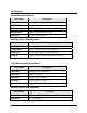
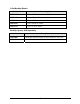
Part Numbers 20-Slot Rackmount Chassis Part Number Description LMC5200A SNMP Management Module LMC5207A-R2 20-Slot, w/Dual AC Power LMC5208A-R2 20-Slot, w/Dual DC Power LMC5227A-R2 20-Slot, W/Fixed Single AC Power LMC5228A 20-Slot, w/ACDC Power Back Up, Spares, Sold Separately Part Number Description LMC5210A Power Supply Module for LMC5207A-R2 LMC5210A-R2 Power Supply Module for LMC5207A-R2 LMC5212A Power Supply Module for LMC5208A-R2 LMM090 Serial Cable for SNMP, DB9 Male to DB9 Femal
3-Slot Desktop Chassis Part Number Power Supply 2 LMC5233A 3-Slot, w/AC Power LMC5234A 3-Slot, w/Dual AC Power LMC5235A 3-Slot, w/DC Power LMC5236A 3-Slot, w/Dual DC Power LMC5237A 3-Slot, w/ ACDC Power Back Up, Spares, Sold Separately Part Number Description LMC5200A SNMP Management Module includes Black Box and iView² LMC5238A 19 inch Rackmount shelf and screws 2
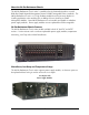
About the 20-Slot Rackmount Chassis The 20-Slot Rackmount Chassis series is a modular chassis platform designed for use with Black Box Simple Network Management Protocol (SNMP) manageable series of modules. The 20-Slot Rackmount Chassis is a 3U high, Rackmountable chassis that features 20 slots for installing application series modules plus an additional slot for installing an SNMP Management Module. Some 20-Slot Rackmount Chassis models are capable of redundant power supply modules.
Reset Alarm Button When one power supply module malfunctions, an audible alarm sounds indicating the loss of the power module. The alarm can be silenced by pressing the Alarm Reset Button, located next to the power connector on the power supply module. If this occurs, remove and replace the power supply module immediately. (LEDs on the Management Module and the power supply module itself also indicate power supply module failures.
LNK/ACT FDX/COL Glows green when a link is established on port. Blinks green when data activity occurs. Glows yellow when port is in Full-Duplex mode. Blinks yellow when port is operating in HalfDuplex mode and collisions occur. TEMP Glows yellow when temperature of unit surpasses a user-defined level. PS Glows yellow when one module malfunctions. FAN A / FAN B Glows yellow when a fan malfunctions.
7. Circuit Overloading - Consideration should be given to the connection of the equipment to the supply circuit and the effect that overloading of the circuits might have on over current protection and supply wiring. 8. Reliable Grounding - Reliable grounding of Rackmounted equipment should be maintained. Particular attention should be given to supply connections other than direct connections to the branch circuit (e.g., use of power strips). 9.
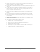
Installing SNMP Management and Application Modules To install a module: 1. Remove the blank bracket (if present) covering the slot where the module will be installed. Black Box recommends installing blank brackets in unused module slots. 2. Slide the module into the chassis using the card guides. 3. Secure the module to the chassis by tightening the captive screw. (Refer to the documentation shipped with the module for configuration information.) 4.
Replacing Power Supply Modules User-Replaceable Power Supply Modules While power supply modules are redundant, failed power supply modules should promptly be replaced to maintain network integrity and prevent data loss. To replace a power supply module: 1. 2. 3. 4. 5. Disconnect the power source from the power supply module. Remove the screws of the retainer plate (on some AC modules). Move the Power Supply Release switch toward the right or unscrew captive release screw.
Dual DC, Part Number LMC5208A-R2 NOTE Do not mix AC and DC power supply modules.
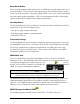
ACDC, Part Number LMC5228A PS1 Status LED PS Release Screw Power Supply Module 1 (PS1) Reset Alarm Switch DC Power Connector PS2 Status LED Power Supply Module 2 (PS2) AC Power Connector Redundant ACDC Power Supply, Close-Up NOTE For LMC5228A 20-Slot Rackmount Chassis, all models in that model number series can support Dual AC, Dual DC or ACDC. The power supply modules for that model number series are interchangeable.
About the 6-Slot Rackmount/Desktop Chassis The 6-Slot Rackmount/Desktop Chassis, is a modular chassis platform designed for use with Black Box Simple Network Management Protocol (SNMP) manageable series of modules. The 6-Slot Rackmount/Desktop Chassis is 1U high, Rackmountable, and supports optional redundant power supply modules, as well as an SNMP Management Module.
• Both power supply modules malfunction • Both power supply modules are powered down • When the AC line fails Temperature Gauge The 6-Slot Rackmount/Desktop Chassis includes a temperature monitoring gauge with a heat sensor on the backplane of the chassis. Users define a threshold for chassis temperature via SNMP. If the chassis’ temperature rises above the specified level, the SNMP agent sends a trap (configured in iView²) to the administrator.
LNK/ACT FDX/COL Glows green when a link is established on port. Blinks green when data activity occurs. Glows yellow when port is in Full-Duplex mode. Blinks yellow when port is operating in HalfDuplex mode and collisions occur. TEMP Glows yellow when temperature of unit surpasses a user-defined level. PS Glows yellow when one power supply module malfunctions. FAN A / FAN B Glows yellow when a fan malfunctions.
8. Reliable Grounding - Reliable grounding of Rackmounted equipment should be maintained. Particular attention should be given to supply connections other than direct connections to the branch circuit (e.g., use of power strips). 9. All AC and DC versions are intended for use in a Restricted Access Location (RAL).
in iView²) to the administrator. There are also two LED indicators on the SNMP Management Module for fan failure. The red Alarm Reset Button also functions as a Fan Test button. To verify fan functionality, hold the button down for several seconds, the fans should engage. The fans will turn off when the button is released. SNMP Management Modules include two twisted pair ports, one for management and one reserved for future use.
6-Slot Rackmount/Desktop Chassis Specifications Input Specifications Dual AC Input 90/264VAC 47-63Hz 1.8A @ 100V 0.8A @ 240V Dual DC Input 35-75VDC, 3.3A Operating Temperature AC DC -25° C to 50° C (-130° F - 122° F) -40° C to 100° C (-40° F - 212° F) Storage Temperature AC DC -40° C to 85° C (-40° F - 185° F) -55° C to 125° C (-67° F - 257° F) Humidity: 5 - 95% (non-condensing); 0-10,000 ft. altitude Shipping Weight: 13 lbs (5.90 kg) Dimensions: 1.75” x 17.35” x 10.65” (4.45cm x 44.07cm x 27.
About the 3-Slot Desktop Chassis The 3-Slot Desktop Chassis series is a modular chassis platform designed for use with Black Box Simple Network Management Protocol (SNMP) manageable series of modules. The 3-Slot Desktop Chassis is a 1U high, a Rackmountable, capable of offering redundant power supply modules, and supports a SNMP Management Module. 3-Slot Desktop Chassis Features The 3-Slot Desktop Chassis series offers a line of models including single AC, single DC, dual AC, dual DC and ACDC version.
Temperature Gauge The 3-Slot Desktop Chassis includes a temperature monitoring gauge with a heat sensor on the backplane of the chassis. Users define a threshold for chassis temperature via SNMP. If the chassis’ temperature rises above the specified level, the SNMP agent sends a trap (configured in iView²) to the administrator. There is also an LED indicator on the SNMP Management Module for chassis temperature.
7. A readily accessible disconnect device shall be incorporated in the building installation wiring. 8. A suitable listed circuit breaker shall be provided in the building installation as the unit’s disconnect device. The branch circuit rating (i.e. minimum 15A listed circuit breaker, etc.). DC Power Wiring, Replacing Power Supply and Fans DC Power Supply Wiring Instructions The following image shows the wiring configuration for a 48 VDC power supply in a negative ground system application.
Fans The 3-Slot Desktop Chassis includes temperature-triggered fans. When the temperature of the chassis reaches 40° C, the two fans activate to cool the chassis. The fans’ operation can be tested by holding the Alarm Reset Button down for 4 to 5 seconds. The fans will activate and then they will turn off when the button is released. If the fans do not activate, contact Black Box. Fans are not end-user replaceable. The red Alarm Reset Button also functions as a Fan Test button.
SNMP Write Lock The SNMP Write Lock switch is located on the back of the 3-Slot Desktop Chassis. The SNMP Write Lock switch prevents a new management board from re-configuring the application module settings (e.g., the status of features such as LinkLoss, FiberAlert, Force mode, etc.) made via SNMP on any previous Management Modules. NOTE Leave this switch in the NORMAL position during day-to-day operation; the LOCKED position should only be used when changing the SNMP management board.
3-Slot Desktop Chassis Specifications Input Specifications AC 100 to 240V AC, 50/60Hz, 0.75A DC 35V DC to 75V DC Max, 1.6A Operating Temperature AC DC 0° C to 50° C (32° F to 122° F) -40° C to 50° C (-67° F to 122° F) Storage Temperature AC DC -40° C to 85° C (-40° F to 185° F) -55° C to 125° C (-40° F to 212° F) Humidity: 5 to 95% (non-condensing); 0 to 10,000 ft. altitude Shipping Weight: 5 lbs (2.3 kg) Dimensions: H=1.73” W=7.45” D=8.74” (4.
Black Box Customer Service Order toll-free in the U.S.: Call 877-877-BBOX (outside U.S. call 724-746-5500) Free technical support, 24 hours a day, 7 days a week. Call: 724-746-5500 or Fax: 724-746-0746 Mail order: Black Box Corporation 1000 Park Drive, Lawrence, PA 15055-1018 Web site: www.blackbox.com E-mail: info@blackbox.com WARNING Disconnect all power supplies before servicing.
Fiber Optic Cleaning Guidelines Fiber Optic transmitters and receivers are extremely susceptible to contamination by particles of dirt or dust, which can obstruct the optic path and cause performance degradation. Good system performance requires clean optics and connector ferrules. 1. 2. 3. 4. Use fiber patch cords (or connectors, if you terminate your own fiber) only from a reputable supplier; low-quality components can cause many hard-to-diagnose problems in an installation.
Certifications UL/CUL: Listed to Safety of Information Technology Equipment, including Electrical Business Equipment. Class 1 Laser product, Luokan 1 Laserlaite, Laser Klasse 1, Appareil A’Laser de Classe 1 European Directive 2002/96/EC (WEEE) requires that any equipment that bears this symbol on product or packaging must not be disposed of with unsorted municipal waste. This symbol indicates that the equipment should be disposed of separately from regular household waste.
Black Box Tech Support: FREE! Live. 24/7. Tech support the way it should be. Great tech support is just 20 seconds away at 724-746-5500 or www.blackbox.com About Black Box Black Box Network Services is your source for more than 118,000 networking and infrastructure products. You'll find everything from cabinets and racks and power and surge protection products to media converters and Ethernet switches all supported by free, live 24/7 Tech support available in 20 seconds or less. © Copyright 2010.