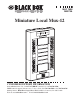
MAY 1998 MX873A Miniature Local Mux-12 SS POWER SYNC LO C TEST REM LO INPUT 9V-DC CUSTOMER SUPPORT INFORMATION Order toll-free in the U.S.: Call 877-877-BBOX (outside U.S. call 724-746-5500) FREE technical support 24 hours a day, 7 days a week: Call 724-746-5500 or fax 724-746-0746 Mailing address: Black Box Corporation, 1000 Park Drive, Lawrence, PA 15055-1018 Web site: www.blackbox.com • E-mail: info@blackbox.
MINIATURE LOCAL MUX-12 FEDERAL COMMUNICATIONS COMMISSION AND INDUSTRY CANADA RADIO FREQUENCY INTERFERENCE STATEMENTS This equipment generates, uses, and can radiate radio-frequency energy, and if not installed and used properly, that is, in strict accordance with the manufacturer’s instructions, may cause interference to radio communication.
MINIATURE LOCAL MUX-12 NORMAS OFICIALES MEXICANAS (NOM) ELECTRICAL SAFETY STATEMENT INSTRUCCIONES DE SEGURIDAD 1. Todas las instrucciones de seguridad y operación deberán ser leídas antes de que el aparato eléctrico sea operado. 2. Las instrucciones de seguridad y operación deberán ser guardadas para referencia futura. 3. Todas las advertencias en el aparato eléctrico y en sus instrucciones de operación deben ser respetadas. 4. Todas las instrucciones de operación y uso deben ser seguidas. 5.
MINIATURE LOCAL MUX-12 10. El equipo eléctrico deber ser situado fuera del alcance de fuentes de calor como radiadores, registros de calor, estufas u otros aparatos (incluyendo amplificadores) que producen calor. 11. El aparato eléctrico deberá ser connectado a una fuente de poder sólo del tipo descrito en el instructivo de operación, o como se indique en el aparato. 12. Precaución debe ser tomada de tal manera que la tierra fisica y la polarización del equipo no sea eliminada. 13.
MINIATURE LOCAL MUX-12 TRADEMARKS USED IN THIS MANUAL Any trademarks mentioned in this manual are acknowledged to be the property of the trademark owners.
MINIATURE LOCAL MUX-12 Contents Chapter Page 1. Specifications. . . . . . . . . . . . . . . . . . . . . . . . . . . . . . . 7 1.1 Sub Channels. . . . . . . . . . . . . . . . . . . . . . . . . . . . 7 1.2 Main Channel . . . . . . . . . . . . . . . . . . . . . . . . . . . 8 1.3 General . . . . . . . . . . . . . . . . . . . . . . . . . . . . . . . . 8 2. Introduction . . . . . . . . . . . . . . . . . . . . . . . . . . . . . . . 10 2.1 General . . . . . . . . . . . . . . . . . . . . . . . . . . . . . . . .
MINIATURE LOCAL MUX-12 Contents (continued) Chapter Page 4. Operation . . . . . . . . . . . . . . . . . . . . . . . . . . . . . . . . . 20 4.1 General . . . . . . . . . . . . . . . . . . . . . . . . . . . . . . . . 20 4.2 Indicators . . . . . . . . . . . . . . . . . . . . . . . . . . . . . . . 20 4.3 Operating Procedure . . . . . . . . . . . . . . . . . . . . . 20 4.3.1 Powering On the Unit . . . . . . . . . . . . . . . 20 4.3.2 Operation . . . . . . . . . . . . . . . . . . . . . . . . . 21 4.3.
MINIATURE LOCAL MUX-12 1. Specifications 1.1 Sub-Channels Transmission Format—Asynchronous Mode of Operation—Full duplex Data Rate—Up to 19.2 kbps Interface—EIA RS-232/CCITT V.24 Connectors—(12) RJ-45 female Number of Sub-channels—12 Distortion—See Table 1-1. User may select six subchannel operation for reduced distortion by internal strapping. Table 1-1. Performance at various bit rates. Sub-channel Distortion (%) Distortion (%) bit rate (Kbps) 6-channel mode 12-channel mode 19.2 9.6 4.8 2.4 1.
MINIATURE LOCAL MUX-12 1.2 Main Channel Transmission Line—4-wire unconditioned telephone lines (two twisted pairs) Operating Range—1 mile (1.6 km) maximum on 22 AWG cable (actual distance may vary, depending on the cable you use) Data Rate—1.2288 Mbps Output Format—Balanced bipolar transformer isolated Output Level—6 V ptp (on 100 ohms) Input Resistance—110 ohms Connectors—(1) RJ-45 female 1.3 General Indicators—Power, Local Sync Loss, Remote Sync Loss Table 1-2. Indicators.
MINIATURE LOCAL MUX-12 Temperature—32 to 122°F (0 to 50°C) Humidity—Up to 95%, noncondensing Power Consumption—Input: 110 VAC, Output: 200 mA @ 9 VDC Size—1.3"H x 4.5"W x 7.4"D (3.4 x 11.4 x 18.7 cm) Weight—10.7 oz.
MINIATURE LOCAL MUX-12 2. Introduction 2.1 General The Miniature Local Mux-12 is a time-division multiplexor that enables up to 12 terminals to be multiplexed onto a single cable, in point-to-point applications. The Mux-12 contains a built-in line driver that extends the high-speed multiplexed data over twisted pairs. 2.2 Functional Description The Mux-12 has 12 sub-channels that are connected by RJ-45 connectors accessible from the top panel.
MINIATURE LOCAL MUX-12 NOTE Whenever possible (when the number of channels is 6 or less), we advise operating the Mux in the 6-channel mode, which results in less distortion. Table 2-1. Performance at various bit rates. Sub-channel Distortion (%) Distortion (%) bit rate (kbps) 6-channel mode 12-channel mode 19.2 9.6 4.8 2.4 1.2 12.5 6.3 3.2 1.6 0.8 25 12.5 6.3 3.2 1.6 2.3 Applications The primary application of the Mux-12 is for point-topoint configurations at distances of up to 0.6 miles (1 km).
MINIATURE LOCAL MUX-12 Miniature Local Mux-12 Host Terminals Figure 2-1. Typical point-to-point installation. For installations involving clusters of terminals distributed in several locations, the Mux-12 units may be installed in a ring-type configuration as shown in Figure 2-2. At each site, the unconnected channels must be bypassed by shorting TX pin to RX pin of the relevant sub-channel’s connector.
MINIATURE LOCAL MUX-12 Host Miniature Local Mux-12 Miniature Local Mux-12 Terminals Miniature Local Mux-12 Terminals Figure 2-2. Typical ring installation.
MINIATURE LOCAL MUX-12 3. Installation 3.1 General This chapter provides the information you need to implement the mechanical and electrical installation of the Mux-12. After installation is complete, refer to Chapter 4 for operating information and system checkout to assure normal operation. 3.2 Physical Installation The Mux-12 comes completely assembled and is designed to be secured to a bench or wall using screws. 3.3 Site Preparation The Mux-12 is installed within 5 ft. (1.
MINIATURE LOCAL MUX-12 1. Open the top half of the plastic case by squeezing the marked places on the sides. 2. Strap the multiplexor for 6 or 12 sub-channels according to the printed circuit board. 3. To close the unit, simply press the two halves of the case together. 4. Install the Mux within 5 ft. (1.5 m) of an AC outlet. The unit can be wall-mounted by four screws through the mounting brackets located at both sides of the unit. 5.
MINIATURE LOCAL MUX-12 of one unit should be connected to the Receive Pair of the other unit, and vice versa. All LEDs should be “OFF” (with the exception of “POWER”) indicating normal operation. 3.5 Electrical Installation 3.5.1 AC POWER The Mux is powered by an external power supply of 9 to 12 VDC capable of supplying at least 300 mA. A miniature wall-mount power supply can be used to provide the required power.
MINIATURE LOCAL MUX-12 Table 3-1. Sub-channel connector pin assignments. CCITT V.24 EIA RS-232C Pin No. Signal Name Description 102 103 AB BA 7 5 Signal Ground Transmit Data 104 BB 3 Receive Data 105 106 107 CA CB CC 2 8 6 Request to Send Clear to Send Data Set Ready 109 CF 4 Receive Line Signal Detector (Carrier Detect) — — 1 +V output Common signal. Serial data from DTE into the Mux. Serial data output from the Mux Connected to CTS. Connected to RTS.
MINIATURE LOCAL MUX-12 1 8 Figure 3-1. RJ-45 socket (female) external view.
MINIATURE LOCAL MUX-12 1 8 Figure 3-2. RJ-45 plug (male) clip at rear.
MINIATURE LOCAL MUX-12 4. Operation 4.1 General This chapter contains a list of the Mux-12’s indicators, their functions and operating procedures. Installation procedures given in Chapter 3 must be completed and checked before attempting to operate the Mux. 4.2 Indicators Four indicators are located on the Mux’s top panel (see Figure 4-1). Their functions are described in Table 4-1. Table 4-1. Indicator functions.
MINIATURE LOCAL MUX-12 the remote Mux is still not operational, the SYNC LOSS indicators should be lit. 4.3.2 OPERATION The Mux operates entirely unattended except when occasional monitoring of LED indicators is required. 4.3.3 POWERING OFF THE UNIT To power off the Mux, simply remove the power adapter from the AC source. 4.4 Operational Field Strapping Changes If you need to reconfigure the Mux for 6- or 12-channel mode, simply follow the appropriate setup procedure given in Section 3.2.
MINIATURE LOCAL MUX-12 5. Diagnostics 5.1 Remote Loopback Remote loopback can be performed by the Mux-12 when operated in conjunction with the single-port Miniature Local Mux. The test is performed by pressing the RLB button switch located on the front panel of the single-port Mux, which results in looping data back from the remote Mux-12’s receiver to the transmitter.
MINIATURE LOCAL MUX-12 WARNING These service instructions are for use by qualified personnel only. To avoid shock, do not perform any servicing other than that contained in the operating instructions unless you are qualified to do so. Table 5-1. Fault isolation and troubleshooting. Symptom Action All front-panel indicators are off a) Check that power is supplied to the unit. b) Replace unit. The fault is probably in the unit’s powersupply circuits.
MINIATURE LOCAL MUX-12 Appendix: Bracket Assembly 1. The Mux is provided with two mounting brackets, which mate with a pair of slots on each end of the Mux case. 2. Each bracket has a pair of flanges that slide into the Mux case slots. Mounting Flanges Figure A-1. Top view of mounting bracket. 3. To attach the brackets, hold the Mux case facing upward. Slide the bracket flanges firmly into their slots on the Mux case. When slid all the way, the brackets snap into a locked position.
MINIATURE LOCAL MUX-12 Figure A-2. Before mounting the brackets. Figure A-3. After mounting the brackets.
© Copyright 1998. Black Box Corporation. All rights reserved.