
Specifications

15
MINIATURE LOCAL MUX-12
1. Open the top half of the plastic case by squeezing
the marked places on the sides.
2. Strap the multiplexor for 6 or 12 sub-channels
according to the printed circuit board.
3. To close the unit, simply press the two halves of the
case together.
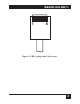
4. Install the Mux within 5 ft. (1.5 m) of an AC outlet.
The unit can be wall-mounted by four screws
through the mounting brackets located at both
sides of the unit.
5. Connect 9 to 12 VDC from a wall-mounted AC
adapter into the DC jack of the Mux. The
“POWER” LED should be lit. Other LEDs may be
lit as well.
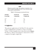
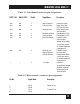
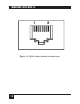
6. Connect the sub-channels to your equipment. Pin
assignment of the RJ-45 sub-channel connector is
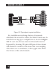
given in Table 3-1. For a description of the RJ-45
connector, see Figure 3-2.
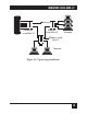
7. Connect the main channel of the Mux to the
wiring that connects it to the remote Mux. Pin
assignment of the RJ-45 main channel connector
is given in Table 3-2. Note that the Transmit Pair