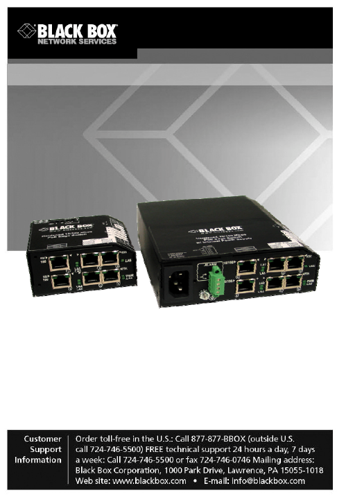
LPH240A-H LPH240A-P PoE Edge Switch Use this economical 6-port 10/100 switch, which has four 802.3af compliant PoE PSE ports for PoE devices. Reduces Network Costs and provides economical solution. Operation is plug-and-play.
Radio Interference Regulations Federal Communications Commission and Industry Canada Radio Frequency Interference Statements This equipment generates, uses, and can radiate radio-frequency energy, and if not installed and used properly, that is, in strict accordance with the manufacturer’s instructions, may cause interference to radio communication.
NOM Statement Instrucciones de Seguridad (Normas Oficiales Mexicanas Electrical Safety Statement) 1. Todas las instrucciones de seguridad y operación deberán ser leídas antes de que el aparato eléctrico sea operado. 2. Las instrucciones de seguridad y operación deberán ser guardadas para referencia futura. 3. Todas las advertencias en el aparato eléctrico y en sus instrucciones de operación deben ser respetadas. 4. Todas las instrucciones de operación y uso deben ser seguidas. 5.
NOM Statement 11. El aparato eléctrico deberá ser connectado a una fuente de poder sólo del tipo descrito en el instructivo de operación, o como se indique en el aparato. 12. Precaución debe ser tomada de tal manera que la tierra fisica y la polarización del equipo no sea eliminada. 13.
Trademarks Used in this Manual Trademarks Used in this Manual Black Box and the Double Diamond logo are registered trademarks of BB Technologies, Inc. Ethernet is a trademark of Xerox Corporation NEBS is a trademark of Telcordia Technologies UL is a registered trademark of Underwriters Laboratories Any other trademarks mentioned in this manual are acknowledged to be the property of the trademark owners.
Table of Contents Table of Contents 1. SPECIFICATIONS .......................................................................... 9 Technical Specifications ........................................................ 9 Ordering Information............................................................ 14 2. INTRODUCTION .......................................................................... 19 2.1 Inspecting the Package and Product ................................... 19 2.2 Product description ...............
Table of Contents 5. TROUBLESHOOTING ................................................................. 50 5.1 Before Calling for Assistance .............................................. 51 5.2 When Calling for Assistance................................................ 52 5.3 Return Material Authorization (RMA) Procedure ................. 53 5.4 Shipping and Packaging Information ................................... 54 APPENDIX A: WARRANTY INFORMATION .........................................
Chapter 1: Specifications 1. SPECIFICATIONS 1.1 Technical Specifications Ports Performance When a port is operating at 100Mbps: Data Rate: 100Mbps When a port is operating at 10 Mbps: Data Rate: 10 Mbps Network Standards 100Mb: Ethernet IEEE 802.3u, 100BASE-TX, 100BASE-FX 10 Mb: Ethernet IEEE 802.3, 10BASE-T PoE: IEEE 802.3af Auto-sensing for speed: IEEE 802.
Chapter 1: Specifications Maximum Ethernet Segment (or Domain) Lengths 10BASE-T (Unshielded twisted pair) - 100 m (328 ft) 100BASE-TX (CAT 5 UTP) - 100 m (328 ft) 100BASE-FX, half-duplex: (multi-mode) - 412 m (1350 ft) 100BASE-FX, full-duplex: (multi-mode) - 2 km (6562 ft) 100BASE-FX, half-duplex: (single-mode) - 412 m (1350 ft) 100BASE-FX, full-duplex: (single-mode) - 20 km (65,620 ft) Operating Environment LPH240A-H: -13ºF to 140ºF (-25ºC to 60ºC) Long term per agency tests (UL) -40ºF to 185ºF (-40ºC to
Chapter 1: Specifications Altitude (All models): -200 to 5000ft. (-60 – 15,000 m) Conformal Coating (optional) for humidity protection Note: H and P models are designed for NEBS compliance, including vibration, shock and altitude. Packaging: Enclosure: Rugged sheet metal (Steel). Dimensions of the Switch unit: 3.7 in H x 3.0 in W x 1.7 in D (9.4 cm x 7.6 cm x 4.3 cm) Weight: all models: 9.5 oz. (285g); Cooling Method: Convection on the office model.
Chapter 1: Specifications Direct DC POWER SUPPLY: built-in terminal block for +, -, ground -48V DC internal (range 46 to 60V DC),+ , -, ground. Total power input required: for PoE ports, 66 Watts max. OR 1.4A @48VDC Power Consumption: Typical 3.5 watts, 4 watts max. (All six copper ports) Power Consumption: Typical 7 watts, 8.5 watts max. (4 PoE+ 2 non-PoE fiber port) AC POWER SUPPLY ( using an external power adapter): LPH240A-X-XX-48 models have an (8-15)VDC, 2.5-mm center +ve jack.
Chapter 1: Specifications LED Indicators (Front) POWER: 10/100: LK/ACT: F/H: Steady ON when power applied Steady ON for 100Mbps; OFF for 10 Mbps (copper ports only) Steady ON for LINK (LK) with no traffic, BLINKING indicates port is transmitting / receiving (ACT). Steady ON for full-duplex, OFF for half-duplex (Fiber port only) Mounting options Metal mounting clips for panel mounting: included DIN-Rail mounting option: Model # DIN-RAIL MC2 (see Section 3.
Chapter 1: Specifications 1.2 Ordering Information MODEL DESCRIPTION LPH240A-H-48 6 port Hardened-rated PoE (802.3af) Power sourcing Edge switch, four RJ-45 (PoE) + two RJ-45 port (non-PoE), 48VDC terminal block for power input. LPH240A-H-SC-48 6 port Hardened-rated PoE (802.3af) Power sourcing Edge switch, four RJ-45 (PoE) + one Multimode SC port (non-PoE), one RJ45 (nonPoE), 48VDC terminal block for power input. LPH240A-H-SSC-48 Same as above, except a Singlemode SC replaces the Multimode SC port.
Chapter 1: Specifications Ordering Information con’t MODEL DESCRIPTION LPH240A-P-48 6 port Extreme-rated PoE (802.3af) Power sourcing Edge switch, four RJ-45 (PoE) + two RJ-45 ports (non-PoE), 48VDC terminal block for power input. LPH240A-P-SC-48 6 port Extreme-rated PoE (802.3af) Power sourcing Edge switch, four RJ-45 (PoE) + one Multimode SC port (non-PoE), one RJ-45 (nonPoE), 48VDC terminal block for power input. LPH240A-P-SSC-48 Same as above, except a Single-mode SC replaces the Multimode SC port.
Chapter 1: Specifications Ordering Information con’t MODEL DESCRIPTION LPH240A-H 6 port Hardened-rated PoE (802.3af) Power sourcing Edge switch, four RJ-45 (PoE) + two RJ-45 ports (non-PoE), AC IEC320 connector for power input. 6 port Hardened-rated PoE (802.3af) Power sourcing Edge switch, four RJ-45 (PoE) + one Multimode SC port (non-PoE), one RJ45 (nonPoE), AC IEC320 connector for power input. Same as above, except a Single-mode SC replaces the Multimode SC port.
Chapter 1: Specifications Ordering Information con’t MODEL DESCRIPTION LPH240A-P 6 port Extreme-rated PoE (802.3af) Power sourcing Edge switch, four RJ-45 (PoE) + two RJ45 port (non-PoE), AC IEC320 connector for power input. 6 port Extreme-rated PoE (802.3af) Power sourcing Edge switch, four RJ-45 (PoE) + one Multimode SC port (non-PoE), one RJ45 (nonPoE), AC IEC320 connector for power input. Same as above, except a Singlemode SC replaces the Multimode SC port.
Chapter 1: Specifications LPH240A-H-48 (shown) LPH240A-H (shown) Page 18 724-746-5500 | blackbox.
Chapter 2: Introduction 2. INTRODUCTION 2.1 Inspecting the Package and Product Examine the shipping container for obvious damage prior to installing this product; notify the carrier of any damage that you believe occurred during shipment or delivery. Inspect the contents of this package for any signs of damage and ensure that the items listed below are included.
Chapter 2: Introduction 2.2 Product description LPH240A Industrial PoE switch is a reliable and premium-rated Industrial Ethernet product Switch. Strictly designed to be IEEE 802.3af compatible, the 4-port PoE Edge switch, not only provides PoE options on port #3, 4, 5 and 6 but is also equipped with a LLL (Link-Loss-Learn) feature on port #1 and 2 for use in self-healing redundant LAN structures.
Chapter 2: Introduction The LPH240A switch ports follow an auto-sensing algorithm, so that they provide power only to 802.3af, PoE end devices. PoE is managed by a multi-stage handshake to protect equipment from damage and to manage power budgets. The LPH240A ports will discontinue supplying power when the PoE powered devices are disconnected (on incorrect impedance value). LPH240A units support the 802.3af PoE PSE standard for over-current protection, under-current detection, and fault protection.
Chapter 2: Introduction These are applications where the LPH240A can be used to provide the power and data for these PoE Powered Devices, which require 12-13 watts maximum. - Wireless LAN access points and WLAN Mobility system - VOIP phones - Remote Security Camera - SNTP Clock - Factory floor and building control monitoring (Temperature, Smoke, Heat and other environmental sensors).
Chapter 2: Introduction The LPH240A(PoE) Switch provides edge access Ethernet ports in a convenient and compact package. For fiber connectivity of additional non-PoE ports, simply use port#1 and 2 (two RJ-45 or 100 Mb fiber ports with LLL feature) to meet the Fiber and copper 10 or 100 Mb requirements. All LPH240A Power Source Edge Switch models come with two (2) sets of LED indicators.
Chapter 2: Introduction There is no way to filter frames with a bad CRC (the entire frame must be present in order for CRC to be calculated). Since collisions and bad packets are more likely when traffic is heavy, store-and-forward switch technology enables more bandwidth to be available for good packets when the traffic load is greatest.
Chapter 2: Introduction Another feature implemented in LPH240A Series Edge Switches is a collision-based flow-control mechanism (when operating at half-duplex only). When the Switch detects that its free buffer queue space is low, the Switch prevents more frames from entering by forcing a collision signal on all receiving half-duplex ports in order to stop incoming traffic.
Chapter 2: Introduction 2.4 Features and Benefits Full 100Mb or 10 Mb switching services for high performance Ethernet LPH240A Series PoE Switches provide Fast Ethernet switching on all ports. They perform high speed filter/forward operations on the traffic, giving each port’s segment a full 100Mb (or 10 Mb) of bandwidth. Economical 4-port 10/100 Power Source Switch for PoE devices The compact and robust LPH240A(PoE) acts as a Power plug for all the PoE devices, e.
Chapter 2: Introduction Installation is “Plug and Play”, operation is transparent to software The LPH240A Series PoE Switches operate as hardware switches, only forwarding those packets from each domain that are needed on the other domains. Internal address tables are self-learning, enabling users to change port connections or 10/100 domains without affecting operations. Two sets of LEDs for viewing status from any angle.
Chapter 2: Introduction MDIX ports to eliminate cross-over cables while cascading All the LPH240A Series Switches are featured with MDI-X (autocross), which easily allows cascading with other Switches, Hubs or media Edges without using the cross-over cable. DC-Power input for PoE Power Source Switch The 802.3af PoE standard power source switch requires 1.4 Amp48VDC to provide enough power for 13-15watts on each RJ-45 port. The Terminal block for -48V DC input is a range of 46V to 60V DC.
Chapter 3: Installation 3. INSTALLATION This section describes the installation of the LPH240A Series PoE Edge Switches, including location, mountings, power supply options and media connections. 3.1 Locating the Edge Switch Unit All the LPH240A Series Switches operate in transparent halfand full-duplex mode. The store and forward switches easily take care of network traffic and can be used as a useful, economical tool to expand an existing network.
Chapter 3: Installation Fig. 3.1a LPH240A-x-48VDC (48V model) Page 30 724-746-5500 | blackbox.
Chapter 3: Installation Fig. 3.1b LPH240A-x (AC model) 724-746-5500 | blackbox.
Chapter 3: Installation 3.2 LE1505-RACK for Rack Mounting of LPH240A (48V models only) For 19” rack-mounting of LPH240A Series Switches, a rackmount tray is available, the LE1505-RACK. The Switches are mounted with the DC power jack in the back, with the fiber and the RJ-45 connectors in the front. (The mounting spaces of the LE1505-RACK are specific to the LPH240A products and will not permit other models to be properly mounted).
Chapter 3: Installation 3.3 LH1505P-RACK for Rack Mounting (48V models only) The LH1505P-RACK is another option for rack mounting the LPH240A Switches together in a 19” rack-mount tray. These models come with a built-in common universal AC power supply rated at 55 watts at 50°C ambient, 9 VDC regulated output, and supporting up to 10 Switches for LH1505P-RACK.
Chapter 3: Installation 3.4 DIN-Rail mounting option The LPH240A Switches, designed for use in “Factory Floor” Industrial Ethernet environments, are also available for DIN-Rail mounting in an enclosure having DIN Rails. The metal DIN-Rail mounting hardware is optional and needs to be ordered as a separate item. DIN Rail bracket pn: DIN-RAIL MC2 LPH240A-H-48V LPH240A-H Page 34 724-746-5500 | blackbox.
Chapter 3: Installation 3.5 Power Requirement for LPH240A (48V) Edge Switch POWER INPUT: Total Power Consumption: 66 watts max. (1.5A @48VDC) (4PoE+2 non-PoE) copper Total Power Consumption: 66 watts max. (1.6A@48VDC) (4PoE copper+2 non-PoE fiber) Terminal block for -48v DC input (range of 46 to 60V dc), built in for +, - , ground. Note: The 8-15V DC option is also present, but can only be used to power the LPH240A unit when no PoE devices are attached.
Chapter 3: Installation 3.6 Powering the LPH240A with –48VDC power input Each LPH240A Switch is equipped with an internal DC power supply, and has built-in screw terminals for secure attachment of the power input leads. The three DC power input terminal block choices are for use with -48VDC power. Where an AC power adaptor is used, DC is supplied via the jack. Power input from the DC terminal block and the jack may be connected simultaneously for power input redundancy. Page 36 724-746-5500 | blackbox.
Chapter 3: Installation 3.7 LPH240A Series, DC-powered, -48VDC Installation This section describes the proper connection of the -48VDC leads to the DC power terminal block on the LPH240A PoE Edge Switch. The DC terminal block on the LPH240A is located on the left side of the unit and is equipped with three (3) screw-down lead posts.
Chapter 3: Installation 3.8 Connecting Ethernet Media The LPH240A-Series PoE Edge Switches can be connected to two media types i.e. fiber and copper (RJ-45) types, run at 100BASE-TX, 10BASE-T and 100BASE-FX only. CAT 5 cables should be used when making 100BASE-TX connections. When the ports are used as 10BASET ports, CAT 3 may be used. In either case, the maximum distance for unshielded twisted pair cabling is 100 meters (328 ft). For fiber port 10BASE-FL or 100BASE-FX multi-mode, 50/125 or 62.
Chapter 3: Installation 3.8.1 Connecting Twisted Pair (RJ-45, CAT 3 or CAT 5, Unshielded or Shielded) The following procedure describes how to connect a 10BASE-T or 100BASE-TX twisted pair segment to the RJ-45 port. The procedure is the same for both unshielded and shielded twisted pair cables. 1. 2. 3. 4. Using standard twisted pair media, insert either end of the cable with a RJ-45 plug into the RJ-45 connector of the port.
Chapter 3: Installation 3.8.2 Connecting Fiber Optic ST-type, “twist-lock” The following procedure applies to installations using ST-type fiber connectors. This procedure applies to ports using multi-mode ST fiber connectors. 1. 2. Before connecting the fiber optic cable, remove the protective dust caps from the tips of the fiber connectors. Save these dust caps for future use. Wipe clean the ends of the dual connectors with a soft cloth or lintfree lens tissue dampened in alcohol.
Chapter 3: Installation 3.8.3 Connecting Fiber Optic SC-type, "Snap-In" The following procedure applies to installations using SCtype fiber connectors, i.e., using multi-mode SC and SC single-mode. While connecting fiber media to SC connectors, simply snap on the two square male connectors into the SC female jacks of the Fiber connector until it clicks and secures. 3.8.4 Connecting Single-Mode Fiber Optic When using single-mode fiber cable, be sure to use singlemode fiber port connectors.
Chapter 3: Installation 3.8.5 Power Budget Calculations, Fiber Media Receiver Sensitivity and Transmitter Power are the parameters necessary to compute the power budget.
Chapter 3: Installation 3.8.6 Connections to NICs which support Auto-Negotiation, RJ-45 ports The copper ports of LPH240A Edge Switches will function properly with NICs (Network Interface Cards) which support AutoNegotiation, and the Fast Link Pulse (FLP) coding for the 100BASE-TX signaling system. When connecting a NIC to the LPH240A-Series, it may be necessary to reload the NIC drivers on the user device if the NIC has been communicating with a protocol other than 100BASE-TX (such as 10BASE-T).
Chapter 4: Operation 4. OPERATION 4.1 Dual-Speed Functionality, and Switching The LPH240A Series Edge Switches provide SIX switched ports with combination of fiber and copper or copper only. The architecture supports a dual speed switching environment, with standard auto-negotiation capability. The switched RJ-45 ports are full- or half-duplex auto-sensing for mode and speed, and auto-cross for plug polarity. (See Section 4.2).
Chapter 4: Operation Switching, Filtering and Forwarding Each time a packet arrives on one of the switched ports, the decision is taken to either filter or to forward the packet. Packets whose source and destination addresses lie on the same port segment will be filtered, constraining them to one port and relieving the rest of the network from processing them.
Chapter 4: Operation 4.2 Auto-cross (MDIX), Auto-negotiation and Speed-sensing The RJ-45 ports support auto-cross (MDI or MDI-X) in the auto-negotiation mode according to the IEEE 802.3u standard. No crossover cables are needed on RJ-45 port, when connecting the LPH240A Series to other unmanaged switches, legacy hubs, managed switches, media-converter etc.
Chapter 4: Operation 4.3 Dual LEDs, Front-panel and side-panel LED Description PWR Illuminates GREEN to indicate power applied. LK/ ACT Steady ON for LINK w/no traffic, blinking for activity per port. LINK will turn off in the event connectivity is lost between the ends of the twisted pair segment or a loss of power occurs in the unit or remote device. The Link ports are also represented by LA1, LA2, LA3…LA6. (Steady On or steady Off indicates no Receive Activity).
Chapter 4: Operation 4.4 Hardware operated Alarm Contact for monitoring internal power supply The two screws Alarm Contact features are standard on LPH240A Series, and provide Normally Closed (NC) contacts to which the user can attach one sets of status monitoring wires at the green terminal block. When this option is present, the terminal block for Alarm Contacts is part of the Power Input panel in the LPH240A case. The DC power input connection is in the same panel.
Chapter 4: Operation Alarm terminal locations: LPH240A (48V model) LPH240A (AC model) 724-746-5500 | blackbox.
Chapter 5: Troubleshooting 5. TROUBLESHOOTING All Black Box Ethernet products are designed to provide reliability and consistently high performance in all network environments. The installation of Black Box LPH240A Switch is a straightforward procedure (see INSTALLATION, Section 3.0); the operation is also straight forward and is discussed in Section 4. Should problems develop during installation or operation, this section is intended to help locate, identify and correct these types of problems.
Chapter 5: Troubleshooting 5.1 Before Calling for Assistance 1. If difficulty is encountered when installing or operating the unit, refer back to the Installation Section of the applicable chapter of this manual. Also check to make sure that the various components of the network are interoperable. 2. Check the cables and connectors to ensure that they have been properly connected and the cables/wires have not been crimped or in some way impaired during installation.
Chapter 5: Troubleshooting 5.2 When Calling for Assistance Please be prepared to provide the following information. 1. A complete description of the problem, including the following points: a. The nature and duration of the problem; b. Situations when the problem occurs; c. The components involved in the problem; d. Any particular application that, when used, appears to create the problem; 2. An accurate list of Black Box product model(s) involved, with serial number(s).
Chapter 5: Troubleshooting 5.3 Return Material Authorization (RMA) Procedure All returns for repair must be accompanied by a Return Material Authorization (RMA) number. To obtain an RMA number, please contact Black Box Tech support. Please have the following information readily available: Name and phone number of your contact person.
Chapter 5: Troubleshooting 5.4 Shipping and Packaging Information Should you need to ship the unit back to Black Box, please follow these instructions: 1. Package the unit carefully. It is recommended that you use the original container if available. Units should be wrapped in a "bubble-wrap" plastic sheet or bag for shipping protection. (You may retain all connectors and this Installation Guide.) CAUTION: Do not pack the unit in Styrofoam "popcorn" type packing material.
Appendix A: Warranty APPENDIX A: WARRANTY INFORMATION Black Box warrants its products to be free from defects in materials and workmanship for a period of three (3) years from the date of shipment. During this warranty period, Black Box will repair or, at its option, replace components in the products that prove to be defective at no charge other than shipping and handling, provided that the product is returned pre-paid to Black Box.
LPH240A, rev.