LPJ008A-F LPJ008A-FM LPJ008A-T LPJ008A-TM LPJ016A-F LPJ016A-FM LPJ016A-T LPJ016A-TM LPJ024A-F LPJ024A-FM 802.3af and 802.3at PoE Gigabit Injectors Gigabit speed plus extra power for high-wattage BLACK BOX devices. ® Managed and unmanaged versions available. Conform to IEEE 802.af or 802.at specifications. Customer Support Information Order toll-free in the U.S.: Call 877-877-BBOX (outside U.S.
802.3af and 802.3at PoE Gigabit Injectors Trademarks Used in this Manual Black Box and the Double Diamond logo are registered trademarks of BB Technologies, Inc. Windows is a registered trademark of Microsoft Corporation. Any other trademarks mentioned in this manual are acknowledged to be the property of the trademark owners. We‘re here to help! If you have any questions about your application or our products, contact Black Box Tech Support at 724-746-5500 or go to blackbox.
FCC and IC RFI Statements Federal Communications Commission and Industry Canada Radio Frequency Interference Statements This equipment generates, uses, and can radiate radio-frequency energy, and if not installed and used properly, that is, in strict accordance with the manufacturer’s instructions, may cause interference to radio communication.
802.3af and 802.3at PoE Gigabit Injectors Instrucciones de Seguridad (Normas Oficiales Mexicanas Electrical Safety Statement) 1. Todas las instrucciones de seguridad y operación deberán ser leídas antes de que el aparato eléctrico sea operado. 2. Las instrucciones de seguridad y operación deberán ser guardadas para referencia futura. 3. Todas las advertencias en el aparato eléctrico y en sus instrucciones de operación deben ser respetadas. 4.
Table of Contents Table of Contents 1. Specifications.......................................................................................................................................................................................... 6 2. Overview 2.1 2.2 2.3 2.4 2.5 .......................................................................................................................................................................................... 7 Introduction............................
802.3af and 802.3at PoE Gigabit Injectors 1.
Chapter 2: Overview 2. Overview 2.1 Introduction Use the Power over Ethernet (PoE) Injectors to reliably power multiple PoE devices. Ten models are available: • 802.3af PoE Gigabit Injector, 8-Port (LPJ008A-F) • 802.3af PoE Gigabit Injector, 16-Port (LPJ016A-F) • 802.3af PoE Gigabit Injector, 24-Port (LPJ024A-F) • 802.3af PoE Gigabit Managed Injector, 8-Port (LPJ008A-FM) • 802.3af PoE Gigabit Managed Injector, 16-Port (LPJ016A-FM) • 802.3af PoE Gigabit Managed Injector, 24-Port (LPJ024A-FM) • 802.
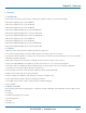
02.3af and 802.3at PoE Gigabit Injectors 2.4 Hardware Description 2.4.1 Front Panel Figure 2-1 shows the front panel of the 24-port PoE Gigabit Injector. Figures 2-2 and 2-3 show close-up views of front-panel components. Table 2-1 describes the front-panel components. 1 3 4 5 2 Figure 2-1. Front panel, 24-port units. 1 2 Figure 2-2. Close-up of front-panel data/power and data ports. 3 4 5 Figure 2-3. Close-up of front-panel Ethernet and USB Type B connectors. Page 8 724-746-5500 | blackbox.
Chapter 2: Overview Table 2-1. Front panel components. Number Component Description 1 (24) RJ-45 ports, top row Data and power ports 2 (24) RJ-45 ports, bottom row Data ports 3 (1) RJ-45 Ethernet connector Links to network interface card (only LPJ008A-FM, LPJ016A-FM, LPJ024A-FM, LPJ008A-TM, LPJ016A-TM models have this connector) 4 USB Type B connector Links to USB 5 AC LED Lights when AC power is connected 2.4.
802.3af and 802.3at PoE Gigabit Injectors 2.5 Safety Procedures: General Precautions Please read the following precautions carefully before installing and connecting the system to a power source: NOTE: Only qualified and trained service personnel (in accordance with IEC 60950 and AS/NZS 3260) should install, replace, or service the equipment. Install the system in accordance with country or national codes, or to the U.S. National Electric Code if you are in the United States. 1.
Chapter 3: Hardware Installation 3. Hardware Installation 3.1 Power Cord Requirements Power cords must meet the requirements for the country where you will use the PoE Injector. U.S. and Canada • The cord must have a minimum of 10-A rated current competence. • The cord must be UL® or CSA approved.
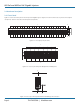
802.3af and 802.3at PoE Gigabit Injectors 3.2 Connecting Ethernet Cables Connect the Ethernet cables (not included) to the PoE Gigabit Injector’s data/power and Ethernet ports. See Figures 3-1 and 3-2. Ethernet cables connected to data and power ports Ethernet port Figure 3-1. PoE Gigabit Injector with Ethernet cables connected to data and power ports. Figure 3-2. Close-up view of PoE GIgabit Injector with cable connected to Ethernet port. 3.
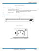
Chapter 3: Hardware Installation Figure 3-4. USB cable connected to PoE Gigabit Injector. AC power cord Connect the AC power cable to the AC power connector on the rear of the PoE Gigabit Injector and the power outlet. See Figure 3-5. IEC-320 power connnector AC power plug Figure 3-5. AC power cord. 3.4 Powering On the Unit The PoE Gigabit Injector receives power via the power cord.
802.3af and 802.3at PoE Gigabit Injectors 3.5.2 Click System Reset on the Graphical User Interface (GUI) 1. AC LED remains green 2. Ethernet LED remains off until the unit is connected 3. 24 ports (with ports connected): same sequence as Cold Start 4. 24 ports (without ports connected): same sequence as Cold Start Table 3-1 LED Indicators.
Chapter 4: Black Box GUI and USB Driver Installation 4. Black Box GUI and USB Driver Installation Locate and download the GUI Installation file from the included CD-ROM. 4.1 PC-to-PoE Gigabit Injector GUI Follow the Installation Wizard to install the Black Box GUI for your model, and the USB-to-Serial COM Port driver. You will need the USB-to-Serial Com Port driver to communicate with the PoE Gigabit Injector via a Communication Port on the PC. See Figures 4-1 and 4-2. Figure 4-1.
802.3af and 802.3at PoE Gigabit Injectors 4.3 Device Manager: to View Port Properties When you are ready to begin, connect the proper end of the USB-to-Serial cable to your PoE Gigabit Injector and the other to an available USB port on your PC. If you installed the USB driver described above, your PC will locate the new hardware. To view which Serial COM Port your PoE Gigabit Injector is installed on, follow these instructions: 1. Click Start—>Control Panel—>System—>System Properties. See Figure 4-3.
Chapter 4: Black Box GUI and USB Driver Installation Figure 4-5. Prolific USB-to-Serial Comm Port screen. Click . Make sure the Port Setting is as shown. Click Com Port Number or stay with the default. . Click on the pull-down menu and select the Figure 4-6. Prolific USB-to Serial Comm Port Properties/Advanced Settings screen. Click to save all changes. NOTE: Write down the COM Port number because the GUI will need to know the exact port on which to search for devices. 724-746-5500 | blackbox.
802.3af and 802.3at PoE Gigabit Injectors 4.4 USB Block Diagram USB device (PoE) internal function USB port (PC) Connects USB port (PC) to PoE device via USB cable Internal USB device sends a signal to your PC, creating a “virtual COM port” (serial communications port). The PC automatically detects the newly installed hardware. This function is called plug-and-play and is available with a USB connection. The PC quickly identifies the connection as serial COM.
Chapter 5: GUI Operation 5. GUI Operation The firmware is supplied with a Graphical User Interface (GUI), which is used to configure and manage the PoE Gigabit Injector system. If you have successfully installed the Black Box GUI and USB driver as described in Chapter 4, go to the GUI on your desktop or from your Start Menu. 5.1 GUI Main Window Step 1: Choose the connection type. See FIgure 5-1. Figure 5-1. GUI main window.
802.3af and 802.3at PoE Gigabit Injectors 5.2 GUI System Information/Operation The System Information/Operation panel on the GUI supports the main system level parameters for the unit. It also displays information about the PoE ID, firmware revision, and system status. Figure 5-3. System setup, control, information, and port commands. The system level parameters that can be configured are: • System Reset: This is a function that allows the GUI to reset the software on the unit.
Chapter 5: GUI Operation 5.3 GUI Port Description The Port Description panel shows 16 ports. On the 8- or 16-Port PoE Gigabit Injector models, the port numbers higher than the system port count will be shaded gray and disabled. Each section specifies the individual port descriptions for the system. Figure 5-5. Port Description. To enable changes to the port configuration in this section, click the “Send Port Control” button. It will send the port information to the unit for 16 ports.
802.3af and 802.3at PoE Gigabit Injectors 5.4 GUI Parametric Information This section allows users to review, but not edit, parametric information for each port. Figure 5-7. Parametric information. The Port Parametric Information panel displays the following set of parameters: • Discovery R (ohms): This value represents the discovered resistance of the port in ohms.
Chapter 6: Troubleshooting 6. Troubleshooting If you have problems with the PoE Gigabit Injector, verify the following: NOTE: The troubleshooting solutions provided can only solve minor problems. If your problem is not listed, contact Black Box Technical Support at 724-746-5500. All up-to-date contact information can be found on our Web site, www.blackbox.com. Problems/Solutions Problem: PoE Gigabit Injector does not power up. Possible Solution #1: Make sure the AC power cord is connected.
Chapter 802.3af and 802.3at PoE Gigabit Injectors Appendix A. Optional Ethernet Interface PC-to-Network-to-PoE Gigabit Injector: CAT5 Cable Network CAT5 Cable PoE Gigabit Injectors PC Figure A-1. PC-to-Network-to-PoE Gigabit Injector diagram. A.1 Network Interface Setup NOTE: Using CAT5 cable, connect the PC to a network of PoE Gigabit Injectors. Skip Step 1 if you will use the Black Box GUI to communicate with the PoE Gigabit Injector. 1. Visit ftp.blackbox.
Appendix A: Optional Ethernet Interface Figure A-2. Ethernet manager screen. 5. If your device is not found, check the connection and click “View”—> “Refresh.” See Figure A-3. Figure A-3. Refresh Ethernet manager screen. 724-746-5500 | blackbox.
802.3af and 802.3at PoE Gigabit Injectors A.2 Advanced Setup Options For advanced setup configuration, click “Config”—>“Device Settings” OR type the IP address in your Internet browser. Your Internet browser will open with the following window: Figure A-4. Controller login screen. 1. Click Setup Login 2. Default User: admin (lower case) 3. Default Password: (leave area blank) NOTE: If you forget your login password, contact Black Box Technical Support at 724-746-5500.
Appendix A: Optional Ethernet Interface A.3 Controller Setup Figure A-5. Controller main window. Port Status: The main window of the controller is a simple GUI that allows the user to enable and disable PoE Gigabit Injector ports. It is also a limited display of parametric information. A more complete list of parametric information is available using the Black Box GUI software available at ftp.blackbox.com. 724-746-5500 | blackbox.
802.3af and 802.3at PoE Gigabit Injectors A.3.1 System Administration Figure A-6. Controller System Administration screen. NOTE: If you change the Administrator name and password, make sure to write it down in a safe place for reference. Click to make any changes permanent. OK Settings have been saved successfully Click to reboot the system with the new changes. This may take a few minutes depending on the connection speed.
Appendix A: Optional Ethernet Interface Configuration Description Table A-1. Controller Setup. Item Default Settings Description Administrator Admin The login administrator is a user-defined name that is used at login. Write down your new Login name in a safe location for future use. Password (Blank) The login password can be empty or 1–14 characters long. Please write down your new password in a safe location for future use. The password is also used while performing SNMP Firmware updates.
802.3af and 802.3at PoE Gigabit Injectors Firmware Update: Click Update to install the most recent firmware for your PoE Gigabit Injector or to re-install a firmware that was backed-up. Before proceeding with this step, make sure that the connection between the PC and PoE Gigabit Injector is secure and will not be interrupted because this may take a few minutes. Figure A-8. Controller firmware update screen. Click “Browse,” then locate your firmware file (it will have a .bin file extension).
Appendix A: Optional Ethernet Interface A.3.2 SNMP Settings The new SNMP v3 has added security features that were not found on previous versions of the management protocol. These include additional password protection. Figure A-9. Controller SNMP settings. Table A-2. SNMP settings. Item Default Settings Description SNMP Versions V1/V2/V3 This function describes the current version of SNMP management that the user is running. This version is V3.
802.3af and 802.3at PoE Gigabit Injectors Table A-2 (Continued). SNMP settings. Item Trap Hosts Default Settings 0.0.0.0 0.0.0.0 0.0.0.0 0.0.0.0 Description Trap hosts are the destination IP addresses that you want the traps to be sent to. You can set the IP addresses in this Controller Setup or by using HyperTerminal. NOTE: The trap notifications are black from entering through the Windows firewall.
Appendix A: Optional Ethernet Interface Figure A-12. Ethernet Manager Set IP Address screen. A.4 DHCP Client: Dynamic or Static Mode Check your Local Area Connection Status: Figure A-13. Local Area Connection Status. Click on . Double-click Internet Protocol (TCP/IP) to view the properties. If the DHCP Client is set to “Disable,” it is in Static mode. You can manually set the IP address, subnet mask, and gateway address for your PC.
802.3af and 802.3at PoE Gigabit Injectors Figure A-14. Local Area Connection Properties/Internet Protocol Properties screen. A.5 Setup NIC PoE Gigabit Injector with Black Box GUI Locate the Black Box PoE GUI on your desktop or from your Start menu. Step 1: Choose Connection Type: SNMP/LAN & WAN and click be sure to input the exact device IP address. to access User Security Parameters. Users should Figure A-15. GUI User Security Parameters screens. Page 34 724-746-5500 | blackbox.
Appendix A: Optional Ethernet Interface NOTE: Make sure that you are using either the community string or SNMPv3 encrypted passwords set via the controller system setup, or the GUI will not detect the PoE Gigabit Injector. To verify the IP address for your PoE Gigabit Injector, use the Ethernet Manager tool mentioned in earlier sections. Figure A-16. GUI User Security Parameters/Ethernet Manager screen. Step 2: Select Search PoE: If a Black Box PoE device is found, click to select the device.
802.3af and 802.3at PoE Gigabit Injectors NOTE: The IP address will be saved internally for the next use. Figure A-18. GUI main window. All features except for the Firmware Download are supported. Please refer to Chapter 5 for the full description of the Black Box GUI features. To update firmware using SNMP, refer to Section A.3. Page 36 724-746-5500 | blackbox.
Appendix B: SNMP MIB Controls Appendix B. SNMP MIB Controls Black Box registered Enterprise ID: 2.3.6.1.4.1.24852 SNMP Version: SNMPv3 TCP, UDP Port: 161 SNMP (Simple Network Management Protocol) Table B-1. SNMP MIB. OID Name Type Value Description 2.3.6.1.24852.2.2.1.0 poeSystemActionHubReset INTEGER ready (0) reset (1) Reset the PoE controller. 2.3.6.1.24852.2.2.2.0 poeSystemActionHubRestoreFactoryDefault INTEGER ready (0) restore (1) Restore factory defaults. 2.3.6.1.24852.2.
802.3af and 802.3at PoE Gigabit Injectors Table B-1 (Continued). SNMP MIB. OID Name Type Value 2.3.6.1.24852.2.2.14.0 poeSystemControlDCPower*** INTEGER Read-write Sets the value of available power in watts to be supplied by secondary (DC) power source. 2.3.6.1.24852.2.2.15.0 poeSystemControlBothPower*** INTEGER Read-write Sets the value of the total available power in watts to be supplied by both power sources. INTEGER Read-only A unique value for each port. 2.3.6.1.24852.2.3.1.1.
Appendix B: SNMP MIB Controls Table B-1 (Continued). SNMP MIB. OID Name Type Value 2.3.6.1.24852.2.2.14.0 poeSystemControlDCPower*** INTEGER Read-write This attribute is cleared through the powerPortCurrentStatusClear action. 2.3.6.1.4.1.24852.2.3.1.5.0 poePortCurrentStatusClear*** INTEGER off(1) Setting the value of this clear(2) object to clear(2) clears the value of the poePortStatus and enables the agent to update the poePortStatus. During Read operation, this value will be off(1). 2.
802.3af and 802.3at PoE Gigabit Injectors Table B-1 (Continued). SNMP MIB. OID Name Type Value Description 2.3.6.1.4.1.24852.2.4.1.1.1~24 poeTrapsControlGroupIndex INTEGER Not-accessible Uniquely describes the (0.65535) group the trap control is located. 2.3.6.1.4.1.24852.2.4.1.2.1~24 porTrapsControlEnable INTEGER Trapsdisabled(1) Enables and disables the TrapsEnabled(2) trap from the agent. OID Name Type Description 2.3.6.1.4.1.24852.2.5.
Appendix B: SNMP MIB Controls Description of Figure B-1: • Building #1 has one main network server that links all three floors together. • Building #2 has one main network server with the network domain of 254.168.2.xxx. Different methods of connection: NOTE: Access control from the controller setup is disabled (allowing all access). Connection within the same network domain. (Refer to the diagram above Building #1 in Figure B-1.
802.3af and 802.3at PoE Gigabit Injectors Appendix C: Frequently Asked Questions Question: What happens if I forget my username and passwords for the Ethernet interface? Answer: Contact Black Box Technical Support at 724-746-5500 or info@blackbox.com.
Black Box Tech Support: FREE! Live. 24/7. Tech support the way it should be. Great tech support is just 30 seconds away at 724-746-5500 or blackbox.com. About Black Box Black Box Network Services is your source for an extensive range of networking and infrastructure products. You’ll find everything from cabinets and racks and power and surge protection products to media converters and Ethernet switches all supported by free, live 24/7 Tech support available in 30 seconds or less. © Copyright 2011.