AUGUST 1999 MD885A-R2 MD885A-R3 MD885AE-R2 MD885C-R2 601745301 Rev. A Modem 34336 4336 EM 3 MOD 1 2 ENT 3 3 2 1 NOTE All models include the modem, (1) leased line cable, (1) dialup phone cable and this user manual. The MD885A-R2, MD885AE-R2, and MD885A-R3 include a power supply. The MD885A-R3 also includes (1) 10-ft. RS-232 cable and (1) DB9 F to DB25 M adapter. CUSTOMER SUPPORT INFORMATION Order toll-free in the U.S.: Call 877-877-BBOX (outside U.S.
FCC Information FEDERAL COMMUNICATIONS COMMISSION AND INDUSTRY CANADA RADIO FREQUENCY INTERFERENCE STATEMENTS This equipment generates, uses, and can radiate radio frequency energy and if not installed and used properly, that is, in strict accordance with the manufacturer’s instructions, may cause interference to radio communication.
Modem 34336 Table of Contents 1.0 Specifications .....................................................................................6 2.0 Quick Start ..........................................................................................8 2.1 2.2 2.3 2.4 2.5 3.0 Unpacking ................................................................................8 2.1.2 Package Contents......................................................................8 2.1.3 What You Will Need.....................
Table of Contents 4.0 3.3.1 V.42 Error Correction Options .............................................35 3.3.2 Dialer Mode ...........................................................................41 3.3.3 Data Format Options .............................................................42 3.3.4 Disconnect Options ...............................................................43 3.3.5 Test Options ...........................................................................44 3.3.6 EIA Options .
Modem 34336 4.10 Automatic Fallback ..................................................................76 4.10.1 Operating Mode Fallback ......................................................76 4.10.2 V.32 Speed Fallback ...............................................................78 4.11 V. 13 Operation ........................................................................80 5.0 Hayes Emulation Mode .................................................................81 5.1 5.2 5.3 5.4 5.5 6.0 7.
Table of Conents 7.6 7.7 Diagnostic Monitoring: Status Screens .................................115 7.6.1 EIA Status Screen .................................................................115 7.6.2 Other Status Screens.............................................................116 Local Modem Diagnostics ......................................................118 7.7.1 Analog Loopback (ALB) Test .............................................118 7.7.2 Analog Loopback Self Test (ALBST) ...............
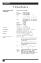
Modem 34336 1.0 Specifications Available Configurations — Compatibility — Stand-alone or rack-mount V.29 V.32 terbo V.33 V.32 bis V.32 V.34+ Data Rates — Data Format — Operation — Fallback — Supported DTE Speeds — Modes — 6 9600, 7200, 4800 19.2 or 16.8 kbps 14.4 or 12.0 kbps 14.4, 12.0, 9.6, 7.2, or 4.8 kbps 9.6 or 4.8 Kbps 33.6, 31.2, 28.8, 26.4, 24, 21.6, 19.2, 16.8, 14.4, and 12 kbps, 9600, 7200, 4800, and 2400 bps V.34 28.8, 26.4, 24, 21.6, 19.2, 16.8, 14.
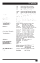
1.0 Specifications Autodialer — Answer Modes — Equalization — Line Requirement — Transmit Timing — Transmit Level — Interface — Carrier Detect Threshold — Test Capabilities — AC Power — Power Consumption — Heat Generation — Ringer Equivalence — Environment — Size (stand-alone unit) — Weight — V.29 QAM at 9600, 7200, and 4800 bps V.27 8-phase DPSK at 4800 and 2400 bps V.26 4-phase DPSK at 2400 and 1200 bps V.23 FSK at 1200/75 bps, full duplex V.22 bis: QAM at 2400 bps; bandsplit, full duplex V.
Modem 34336 2.0 Quick Start All information in this manual applies to both the stand-alone and rackmount versions of the Modem 34336. QUICK SETUPS FOR A QUICK START The simplest and fastest way to set up the Modems for immediate use is to select one of the factory-preset Quick Setup configurations. Quick Setups are explained in Section 2.3, following installation instructions (Section 2.1) and a brief introduction to the Modem’s front-panel display and controls (Section 2.2). 2.1 Installation 2.1.
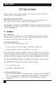
2.0 Quick Start • If you are operating the Modem in a manual dial mode, you also need a standard telephone set. 2.1.4 CONNECTIONS Figure 2-1 shows how the Modem is connected to the computer or terminal, AC power supply, phone lines, and handset. Do not install the modem more than 50 feet (15.2m) from the DTE (the EIA standard maximum length for interface cable). For DTE speeds greater than 19.2 Kbps, a shorter low-capacitance DTE interface cable should be used.
Modem 34336 For dialup applications: • Use the supplied two-conductor crossover cable to connect the Modem to the telephone-line modular wall jack. Plug the eight-pin connector (RJ-45) of the cable into the rear-panel jack labeled TX DIAL. Then, plug the six-pin connector (RJ-12) into the telephone jack. NOTE Do not bundle the telephone and RS-232 cables together.
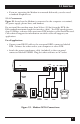
2.0 Quick Start 2.2 Front-Panel LCD and Controls To select a Quick Setup configuration, you will need to use the pushbuttons and liquid-crystal display (LCD) on the modem’s front panel. These features are shown in Figure 2-2. For a detailed explanation of the front panel controls, see Chapter 3. 2.2.1 POWER-ON SCREEN When the Modem is powered on, the LCD momentarily displays the power-on screen. The top line identifies the modem type. The lower line indicates the software revision level.
Modem 34336 2.2.2 EIA STATUS SCREEN The EIA status screen indicates the operational status of the Modem as well as the condition of certain EIA RS-232 leads. The abbreviations that may appear are identified below. Typically, only a few of these abbreviations will be displayed during actual operation. D TR 9600 1 MR RS CS CD 2 3 D = Dial line occupied. R = Ringing (R appears in same position as D). S = Connection secured by security handshake. (S appears in same position as D.
2.0 Quick Start 2.3 Quick Setup To set up the Modem for immediate use (or to quickly change the modem’s configuration for an alternate mode of operation), select one of the factorypreset Quick Setup configurations (see Table 2-1). Your Modem will be ready for operation. You will not need to make further adjustments. When you select a Quick Setup, the Modem uses internal memory to automatically set all of its options to the chosen configuration. All previously-stored option settings are overwritten.
Modem 34336 All options for each Quick Setup configuration are listed in Appendix B. If you want to customize your Quick Setup configuration, see 3.0, Modem Setup Options. For Hayes® mode options, see 5.0, Hayes Emulation Mode. Table 2-1. Available Quick Setup Configurations. QUICK SETUP IDENTIFIED ON LCD DESCRIPTION QUICK SETUP <01> 2-W DIAL (Hayes) 2-WIRE DIAL HAYES EMULATION MODE— This QUICK SETUP <02> V25 DIAL (Async) 2-WIRE DIAL V.25 bis MODE, ASYNCHRONOUS—In V.
2.0 Quick Start Table 2-1 (continued). Available Quick Setup Configurations. QUICK SETUP <07> 2-W LEASED (ANS) 2-WIRE LEASED-LINE ANSWER MODE— QUICK SETUP <08> 4-W LEASED (ORG) 4-WIRE LEASED LINE ORIGINATE MODE— QUICK SETUP <09> 4-W LEASED (ANS) 4-WIRE LEASED LINE ANSWER MODE— QUICK SETUP <10> 4-WLL V.33 V.33 LEASED LINE OPERATION— QUICK SETUP <11> 2-W DIAL (208) 2-WIRE DIAL BELL 208 OPERATION— QUICK SETUP <12> 2-W DIAL V32/208 2-WIRE DIAL V.32/208 AUTO-DETECT MODE— QUICK SETUP <13> 4-WLL V.
Modem 34336 2.4 Basic Operation This section provides basic information for each of the modem’s primary operating modes. If you encounter difficulty, refer to Section 2.5, Problem Solving. 2.4.1 2-WIRE DIAL (HAYES) MODE (QUICK SETUP 1) Two-Wire Dial (Hayes) mode is the factory-default configuration for the Modem. Hayes mode operation and commands are explained in detail in 5.0, Hayes Emulation Mode. Dialing a Phone Number.
2.0 Quick Start Dialing Mode. The default dialing mode is tone dialing. To change to pulse dialing, insert a P after AT D: AT DP To change from pulse dialing to tone dialing, insert a T after AT D: AT DT The specified dialing mode remains active until the alternate mode is specified or the modem is reset. Connected. When a phone number is successfully dialed, a CONNECT message appears on the computer screen and the LCD on the Modem displays a status screen similar to the one shown below.
Modem 34336 For V.25 bis operation, the Modem must be configured to use the same data protocol as the attached DTE. V.25 bis mode operation and commands are explained in detail in Chapter 6.0, V.25 bis Audodialer. Asynchronous V.25 bis Operation. The data format of the DTE should be set to 7 data bits with even parity and one stop bit. The default DTE interface rate is 38,400 bps in asynchronous mode. V.25 bis commands can be entered from the DTE keyboard.
2.0 Quick Start 2.4.3 2-WIRE DIAL (DUMB) MODE (QUICK SETUP 5) Dumb mode is used primarily for manual call origination, answer-only applications, and in conjunction with certain dial back security systems that utilize MI/MIC signals to place the modem on-line. (If you need to configure the modem for MI/MIC use, refer to Appendix D.) For additional information on Dumb-mode operation, refer to Chapter 4.0, General Operation and Special Features. Answering a Call Automatically.
Modem 34336 Autodialing the Stored Number. To autodial the stored number from the EIA status screen, press the following pushbuttons in sequence: ENT Pushbutton 3 (to select DIAL from MAIN MENU screen 1) Pushbutton 1 (to select DIAL from the AUTO-DIAL screen) When the local modem successfully establishes a connection with the remote unit, the EIA status screen should be present. This screen looks like the one shown below.
2.0 Quick Start The following information applies to both 2-wire and 4-wire leased-line operation: • The modem must be configured for the correct line type –– 2-wire or 4-wire. If you select the correct Leased Line Quick Setup, the line type is automatically set to the correct setting. • One modem must be set to originate mode and the other to answer mode. If you select the correct Leased Line Quick Setup, the answer/originate status is automatically set to the correct setting.
Modem 34336 2.4.5 V.33 LEASED-LINE OPERATION (QUICK SETUP 10) V.33 operation is available on the Modem at speeds of 12,000 and 14,400 bps. V.33 leased-line operation provides compatibility with V.33 modems (synchronous operation only). A 4-wire line must be used (conditioned or unconditioned), and both connected modems must be set for V.33 operation. After the V.
2.0 Quick Start 2.4.7 4-WIRE LEASED LINE V.29 MODE (QUICK SETUP 13) The 4-Wire Leased Line V.29 Mode configures the modem for V.29 operation, for compatibility with V.29 modems. Keep these guidelines in mind when using this mode: • The modem must be configured for use with a 4-wire line. • Operation is restricted to data rates of 4800, 7200, and 9600 bps. • Lines can be conditioned or unconditioned.
Modem 34336 2.4.8 V.29 FAST MASTER AND SLAVE MODES (QUICK SETUPS 14 AND 15) In multidrop operation, the master modem transmits to all of the slave (remote) modems. When the DTE at a slave site recognizes its own address in the polling protocol, it raises RTS to the slave transmitter. The slave responds by transmitting a special training sequence, then raising CTS and transmitting the data from the DTE.
2.0 Quick Start 2.5 Problem Solving If you encounter difficulties in setting up or using the modem, try the remedies described below. If you suspect a system malfunction, follow the diagnostic procedures described in Chapter 7. If you cannot resolve the problem, call your supplier. 1. ALL MODES Make sure all cables are properly connected to the back of the modem. 2. ALL DIAL MODES (HAYES, V.25 BIS, DUMB, BELL 208, AND V.
Modem 34336 NOTE This page is intentionally left blank.
3.0 Modem Setup Options 3.0 Modem Setup Options 3.1 Methods For Selecting Options The Modem allows you to easily select options for tailoring the modem’s operation to suit a particular application. You can be select options in the following ways: • Quick Setup — the easiest way to set up the Modem. Quick Setup (explained in Chapter 2) automatically sets all options according to a preset configuration. • Front-panel selection — the easiest and most commonly used method for selecting individual options.
Modem 34336 3.2 Selecting Options from the Front-Panel 3.2.1 PUSHBUTTONS AND THE LCD Options are selected from the front panel by pressing the front panel pushbuttons (Figure 3-1). The possible choices for each option are shown on the liquid crystal display (LCD) and on the flow chart at the back of this manual. 1. Arrow Pushbuttons. Use the left arrow and right arrow pushbuttons to display additional or previous pages (screens) of a menu.
3.0 Modem Setup Options NOTE If you have selected a Quick Setup or have changed certain options settings, pressing the ENT pushbutton to exit the SETUP menu will cause the modem to reset. 3.2.2 HOW TO SELECT OPTIONS Options are configured from the SETUP menu. To access the SETUP menu, press the right-arrow pushbutton at page 1 of the MAIN MENU. This will take you to page 2 of the MAIN MENU. Press push button 1 to select SETUP.
Modem 34336 2. Option-Selection Example. The following example illustrates option selection. As you follow the steps below, refer to the LCD flow chart (SETUP OPTIONS side) at the back of this manual. When you are finished, you can easily restore default settings for the type of application you are using by selecting the appropriate Quick Setup (see Section 2.3, Quick Setup). The example shows how to change the volume of the modem’s speaker from LOW or HIGH (the default setting) to MEDIUM.
3.0 Modem Setup Options Press pushbutton 3 to select SPKVOL (speaker volume). The SPEAKER VOLUME screen is shown right. SPEAKER VOLUME LOW MEDIUM HIGH 1 2 3 The currently selected setting flashes. Press pushbutton 2 to switch the volume setting to MEDIUM. MEDIUM begins to flash, indicating the new selected setting (although the new selection does not become active until you exit the SETUP menu). To return to the first page of the MAIN MENU, press the ENT button several times. 3.
Modem 34336 The default settings for each option are listed in Appendix B. The Quick Setup options (one for each operating mode) affect the entire modem configuration. See Chapter 2. The Line Type options are available for all modes: • 2-WIRE DIAL — for dialup applications. • 2W-LL — for leased-line applications using 2-wire lines. • 4W-LL — for leased-line applications using 4-wire lines. The Speed Limit option (available for all modes) allows you to set a minimum and/or maximum data rate.
3.0 Modem Setup Options Table 3-1.
Modem 34336 • V.32. The Modem normally uses the V.32 handshake. (The Modem also uses this handshake for V.32/14,400 bps operation.) • V.33. V.33 operation is available on the Modem for 4-wire leased line synchronous operation only. The available data rates are 14,400 and 12,000 bps. Either of these rates may be set as the maximum or minimum by using the Speed Limit MAXIMUM RATE and MINIMUM RATE screens. Both connected modems must be set for V.33 leased-line operation. • V.34. V.34 extended (33.
3.0 Modem Setup Options 3.3.1 V.42 ERROR CORRECTION OPTIONS The Modem supports both CCITT V.42 error correction and Microcom Networking Protocol® (MNP®) error correction (classes 1 through 5). V.42 and MNP provide end-to-end error correction through an automatic repeat-transmission request algorithm. Both types of error correction enable the Modem to detect data transmission errors and automatically request retransmission of adversely affected data until it is received correctly.
Modem 34336 The available error correction options are listed below: • V.42 Mode • DTE Speed • MNP Class (class limit) • Break Handling • DTE-DCE and DCE-DTE Flow Control options • V.42 Selection • Flyback Buffer • Buffer Mode/Speed Conversion • Pass-Through Flow Control All of the above options affect the type of error correction selected via the V42 SELECTION screen (discussed below), except that the MNP Class and Flyback Buffer options are applicable only to MNP operation.
3.0 Modem Setup Options The following two options are available through the V42 SELECTION screen: The Protocol option is available for Hayes, V.25 bis, Dumb, and Leased-Line modes (except V.33). • LAPM/MNP — The Modem attempts to establish a connection using the V.42 link access protocol (LAPM/MNP). This is the primary error correction protocol under the CCITT V.42 standard.
Modem 34336 The Buffer Mode/Speed Conversion option Hayes, V.25 bis, Dumb, Leased line modes (except V.33). It enables or disables speed conversion (for asynchronous operation only) between the DTE and modem when error correction is not used. • ENABLE — When error correction is not enabled, the V.42 circuit functions as a buffer between the DTE and the modem and provides transmission speed conversion. • DISABLE — Speed conversion is not allowed. The DTE Speed option is available for Hayes, V.
3.0 Modem Setup Options The DTE-DCE Flow Control options are available for Hayes, V.25 bis, Dumb, and Leased-Line modes (except V.33). • NONE — No flow control is used. • RTS ON/OFF — The Request to Send signal controls data flow from the modem to the terminal. • DC1/DC2 — Inserts control characters (CONTROL-R and CONTROL-Q) in the data stream stop and start the flow of data from a device. • DC1/DC3 (X-ON/X-OFF) — The most common method of flow control.
Modem 34336 The Pass-Through Flow Control options are available for Hayes, V.25 bis, Dumb, and Leased-Line modes (except V.33). Pass-Through Flow Control affects DTEDCE flow control only. This option determines whether flow control characters are passed through the communication channel (but only if control characters are used for flow control). • ENABLE — Flow-control characters are passed to the remote end of the communication connection after the modem acts upon them.
3.0 Modem Setup Options The V.25 bis Dialer Modes are available for V.25 bis mode. Any of the selections from the DIAL V25bis screen will enable the V.25 bis autodialer. For detailed information on the V.25 bis autodialer, see Chapter 6. The three selections on the DIAL V25bis screen allow you to select a data protocol that is appropriate for the DTE the Modem is connected to: • ASYNCHRONOUS (Asyn) • SYNCHRONOUS, CHARACTER ORIENTED (Syn_c) • SYNCHRONOUS, BIT ORIENTED (Syn_b) NOTE DTR dialing for V.
Modem 34336 The Character Length option is available for all modes (asynchronous operation only). It selects a character length of 8, 9, 10, or 11 bits for character asynchronous operation. The same character length must be selected for both the local and the remote modems. Use pushbuttons 1 and 3 to select the desired character length. • 8 BITS: 1 start bit, 6 data bits and 1 or more stop bits. • 9 BITS: 1 start bit, 7 data bits and 1 or more stop bits.
3.0 Modem Setup Options 3.3.4 DISCONNECT OPTIONS When the modem is operating in V.25 bis or Dumb mode, it is necessary to disconnect the modem from the telephone circuit once communications are completed. The most common form of disconnection is by dropping the Data Terminal Ready (DTR) signal from the DTE. However, some applications may require one of the five available automatic disconnect methods listed below.
Modem 34336 3.3.5 TEST OPTIONS The Test Options affect certain tests (as explained below) but do not activate tests. The DSR During Analog Loopback is available for all modes. When ON is selected, the Data Set Ready signal is forced on when the modem is in the analog loopback test mode. In general, this option should be left ON (the default selection). The Remote Test option is available for all modes.
3.0 Modem Setup Options NOTE The Modem also supports a CTS option intended only for V.33 and Bell 208A/B operation, described later in this chapter. The CD to EIA option is available for Hayes, V.25 bis, and Dumb modes. • NORMAL — Carrier Detect (CD) is on while the modem is on-line. • TRUE — CD follows DTR supplied from the DTE.
Modem 34336 The Test Mode (TM to EIA) option is available for all modes. It controls pin 25, the test mode (TM) indicator, on the RS-232 interface connector. • NORMAL — TM output is high (active) only during test modes. • TRUE — TM output is high all of the time. 3.3.7 MODEM SETUPS The options listed below, through RTS-CTS DELAY, are available through the MODEM SETUPS screens. The Carrier Detect option is available for all modes. It selects the carrier detect level.
3.0 Modem Setup Options The Compromise Equalizers option is available for all modes. NOTE The compromise equalizers affect only V.32 operation (4800 to 14,400 bps, asynchronous/synchronous, full duplex). For most applications, the automatic adaptive equalizer setting provides all the equalization necessary to compensate for line impairments, meaning that equalizer adjustments are generally not necessary.
Modem 34336 Normally, as part of the V.32 handshake, the calling modem begins sending a sequence to the answer modem while the answer modem is still sending answer tone. In this case, there is no T1 timer. However, the V.32 recommendation allows for a T1 time of up to 3 seconds, meaning that the answer modem may be set to wait (before falling back) for up to 3 seconds. The B option is available for all modes. If the Modem makes a connection at one of the V.32 rates (4800 to 14,400 bps) or V.
3.0 Modem Setup Options The Speaker Volume option is available for all modes. It can be set to LOW, MEDIUM, or HIGH. The Guard Tones option is available for Hayes, V.25 bis, Dumb modes. Guard tones are used in V.22 and V.22 bis modes only, to assure proper band separation on systems that use international telephone circuits. Unless you are using international circuits in one of these modes, you should turn the guard-tone option OFF.
Modem 34336 The CTS option is available for 4-wire Leased Line modes. It applies only to 4-wire leased line applications using constant carrier. • RTS — The CTS signal follows RTS. • ON — CTS is always ON. NOTE The Modem also supports a CTS to EIA option, which is described earlier in this chapter under EIA OPTIONS. The RTS-CTS Delay (CTS Delay) option is available for V.25 bis, Dumb, Leased line modes. The available RTS-to-CTS delay settings are 0, 15, 50, or 150 ms.
3.0 Modem Setup Options The Turnaround Delay option is available for 208 mode. It is intended for circuits where echo is a problem. It prevents the Modem from receiving an echo of its own transmitted data. When the Turnaround Delay option is on, CD (pin 8) is held low for 150 ms after RTS is turned off. If the modem detects an energy loss during the delay, it turns CD on 52 ms after detecting the loss. If the modem does not detect an energy loss, it turns CD on 52 ms after the end of the delay.
Modem 34336 • Enable — The Modem will check for X-ON/X-OFF (DC1/DC3) flow control characters received from the remote modem to determine whether to stop or start/restart data transmission to the remote modem. A DC3 (or DC2) control character will cause the Modem/Modem 3242–S to stop data transmission and hold data in its buffer until it receives a DC1 control character (which instructs the modem to resume transmission).
3.0 Modem Setup Options The 208 Phase Detection option is for 208 mode. • Normal — Conditions the modem’s 208 receiver for normal modulation detection. • Compensated — Conditions the 208 receiver for compensated modulation detection for improved performance with older 208 modems. The Answer Tone Detection is for 208 mode. • Enable — Conditions the originating modem’s receiver to wait for answer tone detection before going on-line.
Modem 34336 4.0 General Operation and Special Features This chapter describes the following Modem features and operational modes (listed here in the order in which they are presented): • Quick reset • Dumb mode and Bell 208 operation • Phone number storage • Security operation • Leased Line Auto-Recovery • Diagnostic interface control • Dial Line Auto-Recovery • Automatic fallback • DTR dialing • V.
4.0 General Operation and Special Features If a number has been previously stored, the number is displayed on the top line of the LCD (instead of dashes, as shown above). Only one phone number can be stored per cell. To store a phone number, use the right and left arrow pushbuttons to go to the digit you want to change. The character at the current cursor location flashes. Use pushbutton 1 to decrease a number at the current cursor location or pushbutton 3 to increase a number.
Modem 34336 Table 4-1. Dialing Control Characters. Character Function A-D Used in some PBX applications (tone dialing only). L Links a phone number to another number to be dialed as an alternate. T Sets tone-dialing mode. P Sets pulse-dialing mode. R Configures modem for Dial Line Auto-Recovery. Requires / prefix. See DIAL LINE AUTORECOVERY section later in this chapter. W or : (colon) Wait 30 seconds for dial tone before proceeding. , (comma) Inserts 4-second pause. .
4.0 General Operation and Special Features 4.3.1 AUTODIAL BACKUP The Modem automatically dials the stored number to connect over the backup line if it detects poor signal quality (ER) or a loss of carrier detect (CD) on the leased line. The criteria used by the Modem in assessing the condition of the leased line depend upon the settings of the Signal Quality option (one error 3 5 in 10 or 10 bits) and the Carrier Detect Level option (-43, -33 or -26 dBm).
Modem 34336 NOTE If DIAL IF BAD >> (1, 2, 3 or 4) min is selected, the Select option setting of the answer unit must be equal to or less than the Select option of the originate unit. If both modems are set for Manual Recovery, the originate unit is used to autodial the number stored via the PHONE screen without having to change the LINE TYPE setting on either unit. To autodial, access the AUTO-DIAL screen and select DIAL. To return to the leased line, select HANGUP from the AUTO-DIAL screen.
4.0 General Operation and Special Features Recovery from the front panel, enter the phone number to be dialed followed by /R (the Dial Line Auto-Recovery command) on the PHONE screen (shown below). T555-4545/R DEC CTRL INC 1 2 3 If you need assistance, see Section 4.2.
Modem 34336 4.5.1 DIALING A STORED NUMBER DTR dialing allows you to set up the Modem to automatically dial a stored number even when the autodialer is not enabled. To enable DTR dialing, select DTR from the DIALER option screen. When DTR dialing is enabled, an OFF-to-ON transition of DTR causes the Modem to automatically dial the number previously stored using the front-panel LCD. DTR must remain on for at least 50 ms to effect automatic dialing.
4.0 General Operation and Special Features place the handset back on the cradle. The LCD displays the status of the communication. It appears as shown below. D TR MR RS CS 9600 CD 1 2 3 The data link between the two modems is now established, and data transfer begins. An incoming call may be answered manually or automatically. To answer a data call manually, you must disable the Auto-Answer option. Before the call is received, the Modem must be set to TALK, as explained in the previous section.
Modem 34336 4.7 Modem Security Operation In 2-Wire-Dial Hayes emulation mode only, the Modem can be configured to provide security on incoming calls. Remote users attempting to connect to the Modem are required to enter a password. Incoming calls are accepted only if the user enters a valid password. NOTE The security features described in this manual provide a deterrent to unauthorized access. No communications system can be made perfectly secure.
4.0 General Operation and Special Features The modem’s security configuration for password protection is controlled from the DTE by a special set of password commands. The commands are implemented by using the Hayes AT &Z command to store them in memory. If an administrative password is implemented, the AT &Z command will not function until it is unlocked. The Modem incorporates 10 memory locations for storing telephone numbers, passwords, and the password commands listed in Table 4-2.
Modem 34336 Rules for using passwords and password commands are listed below. • Memory locations 0 and 2-9 may be used for storing phone numbers; locations 2-9 may be used to store passwords. • The entire command string, including the AT &Z command, cannot exceed 40 characters. • Passwords and commands may be entered in capitals or lowercase letters. They are stored and displayed as capitals. • For password pass-through operation, / must be the first character in a storage location.
4.0 General Operation and Special Features 2.Unlocking the &V and &Z commands. If an administrative password is implemented, the Hayes compatible &V and &Z commands cannot be accessed unless they are first unlocked using the current administrative password. (&V is used to view the active modem configuration, stored phone numbers, password commands and passwords; &Z is used to store phone numbers, password commands and passwords).
Modem 34336 NOTE Passwords may be stored only in memory locations 2 through 9. 5.Programming a response to a correct password. Enter the following command, replacing CONNECTED with your message: AT &Z0=/UCONNECTED The DTE responds with the specified message when the modem receives a correct password. NOTE The /U command and message can be stored only in memory location 0. 4.8 Modem-Controlled Remote Control Certain modems can be used to remotely control other modems.
4.0 General Operation and Special Features Control Procedure (Modem-to-Modem) Enabling Modem-to-Modem Remote Control Mode To remotely control a modem connected by a direct phone link, access REMOTE screen 1 (shown below). REMOTE CONTROL <1> TEST If you select CONTROL, you will be able to control the front panel of the remote modem from the front panel of the modem you are using.
Modem 34336 Remote control through a rack controller is an especially valuable capability for modem used in high-density 16-slot enclosures. The low-profile modems specially designed for these racks are manufactured without an LCD user interface or control pushbuttons. One way to access the low-profile modems to monitor, test, or configure tham is by using the modem-control feature described below. The controlling modem must be a Modem 34336 equipped with a front-panel LCD and pushbuttons.
4.0 General Operation and Special Features 2. Enter the address or slot number—To enter the address or slot number of the modem to be controlled, press pushbutton 3. If ADDR/C is displayed on REMOTE screen 2, a screen showing ADDRESS: 000,000 on the top line will be displayed. If SLOT/C is displayed on REMOTE screen 2, a screen showing SLOT NUMBER: 01 on the top line will be displayed.
Modem 34336 Modems in rack equpped with rack controller This modem, with LCD pushbuttons, can control any of the shaded (gray) modems. Standalone modems Modems in rack with or without rack controller Figure 4-1. Remote control—address control mode.
4.0 General Operation and Special Features 4.9 Diagnostic Interface Control The diagnostic software built into the Modem supports a special set of commands known as diagnostic port commands. The commands (listed in Table 4-3) are used to configure modems (from either a local or remote location), or to monitor modems for diagnostic purposes. The diagnostic port commands are entered from a computer or terminal keyboard.
Modem 34336 Table 4-3. Diagnostic Port Commands. COMMAND FUNCTION CONNECT g,u Connect to diagnostic port of modem at group address g, unit address u. An address must be specified unless the wildcard character * is used: CONNECT * (meaning Connect to local modem; address unknown/unspecified.). When the connection is made, the DTE displays the modem’s address. Echo, line feed, and Auto-Display are enabled.
4.0 General Operation and Special Features A carriage return [CR] is required at the end of a command line except when the command line consists of only one single-character command. Commands can be entered in upper or lower case. Other diagnostic port commands are available for factory use only. Therefore, some commands that are not listed above may produce a response.
Modem 34336 Table 4-4. Responses To Diagnostic Port Commands. RESPONSE MEANING ERROR Command error (incomplete, wrong syntax, etc.). (If CONNECT or CON is issued without an address or *, the modems will not connect, and there will be no ERROR message.) ADDRESS g,u The Modem has connected with diagnostic port of modem at address g,u (group and unit). Address may be preceded by A, S, or both—see below. A One or more modem alarms has been detected.
4.0 General Operation and Special Features 4.9.4 DTE DISPLAYS When Auto-Display is enabled, an update of the LCD is automatically displayed on the DTE screen each time a command (E, 1, 2, 3, left arrow, or right arrow) is entered to control the front-panel LCD on the connected modem. Auto-Display is enabled when the long-form connect command (CONNECT) is used. Auto-Display is disabled when the CON command is used. However, even with Auto-Display disabled, the D command can be used to display the LCD screen.
Modem 34336 • If you want to disconnect from the diagnostic link without establishing a new link, issue the CONNECT command without an address. 4.10 Automatic Fallback The Modem incorporates two automatic fallback features that are controlled by the user: • Operating Mode Fallback—Provides compatibility with modems that use any of several different operating modes. • V.
4.0 General Operation and Special Features Changing the Operating Mode Fallback parameter to 1 has the following effects: • The Modem is configured for V.22 bis 2400 bps/V.22 1200 and 600 bps/V.21 300 bps/V.23 1200/75 bps fallback operation. As a result, 600 and 1200/75 bps appear as additional selections on the SPEED LIMIT LCD screens. • Fallback to V.22 bis Bell 212A and Bell 103 compatibility is disabled.
Modem 34336 Table 4-6. V.22 bis/V.22/V.21/V.23 FALLBACK. MODE V.22 bis V.22 V.21 V.23 DESCRIPTION 2400 bps asynchronous/ synchronous 1200 and 600 bps asynchronous/synchronous 300 bps asynchronous 1200/75 bps asynchronous All modes are full duplex. The operating mode is controlled through the SPEED LIMIT screens on the LCD in all modes except Hayes mode. See Chapter 3 for details. 4.10.2 V.32 SPEED FALLBACK This feature applies only to V.32 mode operation.
4.0 General Operation and Special Features If Rate Renegotiation Procedure (RRP) is enabled, the modem will automatically fall back or fall forward to a lower or higher data rate in response to changes in signal quality. This may happen at any time during data transmission, and it is done without a retraining procedure. Your data transmission is virtually uninterrupted.
Modem 34336 After you select UP or DOWN, the LCD will automatically switch to the EIA status screen so you can see the result of the rate-change request (i.e., the current data rate, which is displayed in the lower left corner of the EIA status screen). However, if the Modem has reached the minimum or maximum speed, it will not switch to the EIA status screen. NOTE A request to increase the data rate may result in no change in the data rate if the signal quality is poor.
5.0 Hayes Emulation Mode 5.0 Hayes Emulation Mode For easy reference, the following tables appear consecutively at the end of this chapter: • Table 5-1. Hayes Compatible Commands • Table 5-2. Hayes Mode Result Codes • Table 5-3. S Register Functions 5.1 Hayes Mode Autodialer When the Hayes emulation mode is enabled, the Modem emulates a Hayes autodialer and functions like a Hayes modem.
Modem 34336 • Command Sequence. For dialing, a command line begins with AT, followed by a D and the phone number. Other commands should be placed before the dial command—or after the dial command if it is terminated with a semicolon. See the example below: AT M2 V1 D 555-1212; S2=1O The above command instructs the Modem to keep the speaker on (M2), send word result codes (V1), dial (D) 555-1212, end dial command, set register 2 to 1 (S2=1), and go on-line and wait for carrier (O).
5.0 Hayes Emulation Mode • Dial Command Modifiers. Several modifiers can be used with the basic D (dial) command to alter dialing operations. The modifiers are explained below.
Modem 34336 5.1.3 RESULT CODES Result codes (see Table 5-2) are messages sent by the modem to the DTE monitor in response to your commands. Result code options are selected using the V and X commands, as explained below. Result codes may be words (V1 command) or digits (V0). Word codes are preceded and followed by a carriage-return, line-feed sequence. Digit codes are followed by a carriage return.
5.0 Hayes Emulation Mode For most commands, there are parameters—numerical values used with the command specifying the function of the command. For example, the command L controls the modem’s speaker volume. L2 sets the volume to medium. The default value is a predetermined value which is in effect the first time the Modem is powered up or when a reset command is given. The possible parameters and default value for each command are shown in Table 5-1. • A — Quick Answer.
Modem 34336 • H — Telephone Switch Hook. The H command (on-hook) is used to terminate a call. (On-hook corresponds to off-line.) H may also alternate between voice and data transmission during the same call (if your communication software supports this capability). The H1 command (off-hook) activates the telephone line relay, causing a dial tone to be sent after a 2-second delay.
5.0 Hayes Emulation Mode • O — Forced On-Line. For asynchronous operation only. When the modem is on-line, you can return to the command state by entering the escape code (+++). After the desired command is executed, use the O command to force the modem from the command state to the on-line state. • P — Pulse Dial. The P command instructs the modem to pulse dial.
Modem 34336 • Z —Recall Stored User Profile. The Z command resets the modem and recalls a profile of the modem configuration settings previously saved using the &W command. The profile is designated as profile 0 or profile 1 when it is saved using the &W command. • , —Pause. A comma causes the modem to pause for 2 seconds (or time specified in register S8) before processing the next character in a dial string or command.
5.0 Hayes Emulation Mode • ! — Initiate Flash. The ! command causes the Modem to go on-hook for 1/2 second. The command has the same effect as holding the switch-hook button on your telephone down for 1/2 second. Some PBX systems use a flash to transfer calls. • &F — Recall Factory Configuration. The &F command restores the Modem to its original factory configuration, using data stored in ROM. However, the change is not permanent.
Modem 34336 Ring count Wait time before blind dialing Wait time for carrier/dial tone In addition, the &W command does not save stored phone numbers. • &Z — Store Telephone Number. The &Z command is used to store a telephone number dialed using the DS (dial stored number) command. The syntax is &Zm=n, where m specifies the memory location in which the phone number or dial string is stored and n is the number or dial string to be stored.
5.0 Hayes Emulation Mode 5.3.1 READING AND SETTING REGISTERS Use the S command to read the value of a register or to change its value. To read the current value of a register, use the command S?, where the number of the register is specified between the S and the ?—for example, S9?. The decimal value of the register contents is displayed. You may read multiple registers. For example, if you wish to read the current value in registers S0 and S7, enter the following command.
Modem 34336 • S3 — Carriage Return. Register S3 is effective for asynchronous operation only. Normally, the ASCII carriage-return value, 13, is used. • S4 — Line Feed. This register is effective for asynchronous operation only. The line-feed character follows the carriage return only when word result codes are selected (command V1). Line feed can be changed to a null but cannot be totally disabled. • S5 — Backspace. This register is effective for asynchronous operation only.
5.0 Hayes Emulation Mode If the guard time is zero, timing is not a factor. The three escape characters can occur with any timing relationship, but they must be consecutive. Be cautious when assigning small guard times. You may not be able to enter three characters fast enough, especially if the guard time is less than the time required to transmit one character at the current transmission rate. • S18 — Diagnostic Timer. The value in register S18 determines how long a diagnostic test runs.
Modem 34336 5.4 Selecting Options In Hayes Mode In Hayes mode, options may be selected by using one of the following: • AT commands (Table 5-1) • The front panel • The Summary Setup feature The easiest way to change options in Hayes mode is to use the AT commands listed in Table 5-1 or the Modem’s front panel. The following guidelines apply to option selection in Hayes mode: • If an option is changed using an AT command, the change is effective for Hayes mode only, unless option changes are saved to memory.
5.0 Hayes Emulation Mode • If profile 0 is recalled as the active configuration, the LCD screens reflect the profile 0 configuration. • If profile 0 is changed by means of Hayes commands or via the Summary Setup feature and then saved, the changes made are reflected on the LCD and are effective for all modes.
Modem 34336 Table 5-1. Hayes Compatible Commands. COMMAND FUNCTION/EXPLANATION A Quick Answer No parameters. A/ Repeat Previous Command No parameters. B B0 B1 Bell/CCITT Compatibility Mode * Selects CCITT V.22 mode. Selects Bell 212A mode. C1 Modem displays OK; command has no other effect. This response instead of ERROR maintains a degree of compatibility with older modems supporting this command. D Originate Mode For Dialing No parameters.
5.0 Hayes Emulation Mode Table 5-1 (continued). Hayes Compatible Commands. COMMAND FUNCTION/EXPLANATION I I0 I1 Product Code Or Checksum Requests product code. Requests checksum for the Modem’s software. (Only a portion of the checksum displayed via the front panel is displayed in decimal format.) Requests verification of software checksum. Requests the following for each EPROM (programmable memory unit): chip, part and revision number; checksum. Reserved.
Modem 34336 Table 5-1 (continued). Hayes Compatible Commands. COMMAND FUNCTION/EXPLANATION S= Modify S Register Parameters are register and value to be written. S? Read S Register Parameter is the register number. T Tone Dialing No parameters. V V0 V1 Word/Digit Result Code Result codes are transmitted as digits. Result codes are transmitted as words. W Wait For Dial Tone No parameters, but default wait time (register S7) is 30 seconds. X X0 Select Result Code Selects basic result codes, 0-4.
5.0 Hayes Emulation Mode Table 5-1 (continued). Hayes Compatible Commands. COMMAND FUNCTION/EXPLANATION Y Y0 Y1 Long-Space Disconnect* Disables long-space disconnect. Enables long-space disconnect. Z Z0 Z1 Recall Stored User Profile Resets modem and recalls stored user profile 0. Resets modem and recalls stored user profile 1. , (comma) Pause –– No parameters, but default pause time (in register S8) is two seconds. ; (semicolon) Forced Command State No parameters.
Modem 34336 Table 5-1 (continued). Hayes Compatible Commands. COMMAND FUNCTION/EXPLANATION &J Modem displays OK result code; command has no other effect. (The Modem is configured for A/A1 control or MI/MIC control via jumpers JP2 and JP3, as detailed in Appendix D.) &L Modem displays OK result code; command has no other effect. (The Modem is configured for leased line or dialup line operation via the front-panel QUICK SETUP and/or LINE TYPE screens.) &M Can be substituted for &Q.
5.0 Hayes Emulation Mode Table 5-1 (continued). Hayes Compatible Commands. COMMAND FUNCTION/EXPLANATION &T &T0 Test Commands Terminates a test in progress. &T0 must be the last command in a command line. Initiates a local analog loopback test. Initiates a local digital loopback test. Allows the local modem to accept a request from the remote modem for a remote digital loopback test. Prevents the Modem from accepting a request from the remote modem for a remote digital loopback test.
Modem 34336 Table 5-1 (continued). Hayes Compatible Commands. COMMAND FUNCTION/EXPLANATION &Z Store Telephone Number Parameters are 0-9 (available memory locations). B \B0 \B1 Buffer Mode/Speed Conversion * 1 Disables speed conversion. Enables speed conversion. <$!B10> \C \C1 \C2 \C3 \C4 \C5 MNP Class (Limit) * 1 Limits operation to MNP class 1. Limits operation to MNP classes 1 and 2 Limits operation to MNP classes 1 through 3. Limits operation to MNP classes 1 through 4.
5.0 Hayes Emulation Mode Table 5-1(continued). Hayes Compatible Commands. COMMAND FUNCTION/EXPLANATION \N \N0 \N1 \N2 \N3 V.42 Mode * 1 Disables error correction. Enables mandatory mode for error correction. Disables error correction. Enables automatic mode for error correction. \P \P0 \P1 \P2 V.42 Protocol * 1 Selects LAPM protocol only. Selects MNP protocol only. Selects LAPM/MNP protocol (MNP as alternate). \Q V.42 Flow Control * 1 Two parameters may be used (e.g., \Q0,1; \Q3,2 , etc.).
Modem 34336 Table 5-2. Hayes Mode Result Codes. DIGIT CODE WORD CODE MEANING 0 OK Command line executed without errors. 1 CONNECT Carrier detected at 0-300, 1200, or 2400 bps (basic code set). 2 RING Ringing signal detected (in answer mode). (When the Modem detects a ring, it sends a RING result code unless it is in the process of accepting a command. However, the Modem answers the call only if it is set for automatic answer or is given an A command.
5.0 Hayes Emulation Mode Table 5-2 (continued). Hayes Mode Result Codes. DIGIT CODE WORD CODE MEANING 15 CONNECT 4800 Carrier detected at 4800 bps. 18 CONNECT 9600 Carrier detected at 9600 bps. 20 LINKING Modem is dialing numbers that are linked using the L (link) dial modifier. Note: Four additional word codes are BUFFER, MNP, V42, and V42 bis, followed by the DTE interface speed. These codes indicate if the Modem is in buffer, MNP or LAPM (V.42/V.42 bis) mode.
Modem 34336 Table 5-3. S Register Functions. (Only registers intended for user access are listed.
6.0 V.25 bis Autodialer 6.0 V.25 bis Autodialer For international compatibility, the Modem can function as a V.25 bis autodialer. In V.25 bis mode, the Modem is compliant with CCITT recommendation V.25 bis—an internationally recognized standard for serial automatic call origination and answering. The V.25 bis autodialer uses the dialing command set defined by the V.25 bis recommendation. You can store and dial phone numbers from the DTE in both synchronous and asynchronous applications.
Modem 34336 DTR DIALING IN V.25 BIS MODE An alternative to using the V.25bis CRS command to dial a stored number is to use the DTR dialing option. With DTR dialing enabled, the autodialer will dial the number stored in the phone cell displayed in the front-panel AUTODIAL screen when DTR goes high for at least 50 ms. To enable V.25 bis DTR dialing, sue the Summary Setup feature (see Appendix C) to change the parameter for V25 bis DTR dialing to 1.
6.0 V.25 bis Autodialer • DIC — Disregard Incoming Call. The DIC command instructs the autodialer not to answer an incoming call. The DIC command is cancelled when the CIC command is issued or auto-answer is enabled from the front panel. • PRN — Program Normal (Store Number) (Syntax: PRN<|>1;<|>5551212). The PRN command is used to store a number or dial string in a memory address location (cell) so it can be dialed later by specifying only the address.
Modem 34336 Table 6-1. V.25 bis Autodialer Commands. COMMAND FUNCTION CIC Connect incoming call. CRN n Call request—dial number (n) entered on DTE keyboard. CRS m Call request—dial number stored in specified memory address (m). DIC Disregard incoming call. PRN m n Program normal—store number or dial string n in memory address m. RHA Switch to Hayes dialing mode (also resets modem configuration). RLN Request list of all stored numbers. RLN m Request to see number stored at address m.
6.0 V.25 bis Autodialer Table 6-2. V.25 bis Dialing Parameters. (Table also applies to Dumb mode and Bell 208 operation) Characters that can be dialed: Can only be tone dialed: 0—9 A, B, C, D, #, and * L Links a phone number to another number to be dialed as an alternate when the primary number is busy or does not answer. See L - LINK in Section 5.2. P Sets pulse-dialing mode. T Sets tone-dialing mode. W or : (colon) Wait 30 seconds for dial tone before proceeding. [CR] or .
Modem 34336 6.3 Dialing Parameters Table 6-2 lists dialing parameters you can use with the CRN command to modify dialing operations. 6.4 V.25 bis Result Codes Table 6-3 explains the result codes, or responses, that are displayed on the DTE monitor during V.25 bis operation. 6.5 DTR Dialing In V.25 bis Mode An alternative to using the CRS command to dial a stored number is to use the DTR dialing option.
7.0 Diagnostics 7.0 Diagnostics The troubleshooting information in this chapter applies to all Modem applications (all dialup and leased line modes), unless specifically stated otherwise. For specific test procedures, turn to one of the following sections in this chapter: • Section 7.7 — Local Modem Diagnostics • Section 7.8 — Remote Diagnostics 7.1 When And Why To Test If you experience communications difficulties, you should try to isolate the defective component in your communications system.
Modem 34336 7.3 Physical Inspection The next step in isolating a defective component is inspecting the system. If you can trace the problem to a specific site, examine that site. Check the installation of the modem and DTE. Are all cables in good condition and fully connected? Are all components in the system receiving power? Inspect the system as thoroughly as possible. 7.
7.0 Diagnostics 7.5 How to Select and Activate Tests 7.5.1 FRONT-PANEL CONTROL Tests are accessed and activated in the same way options are selected: by using the LCD and front panel pushbuttons (as explained in Chapter 3). To find the LCD screen for a specific test, refer to the LCD flow chart (Diagnostic And Control Functions) at the end of this manual. Once you access the screen for a specific test, press pushbutton 1 to begin the test (select ON). A test status screen is automatically displayed.
Modem 34336 D = Dial line occupied R = Ringing (R appears in same position as D.) S = Connection secured by security handshake (S appears in same position as D. S and D may flash alternately.) TR = Data Terminal Ready MR = Data Set Ready RS = Request to Send CS = Clear to Send TD = Transmit Data 9600, 4800, etc. = Data speed (idle—the Modem is off-line—or H-01, H-14, etc., may also be displayed in the data speed position; see following text.
7.0 Diagnostics The RX value is the local receive level of the incoming signal. The receive level range of measurement is from 0 to -43 dBm in 1.5-dBm increments. If the signal level is less than the carrier detect threshold, "
Modem 34336 7.7 Local Modem Diagnostics Local modem diagnostics are for testing the Modem and its adjoining system. The tests are accessed from the main menu and are easily performed if the Modem is attached to DTE or an external BERT. 7.7.1 ANALOG LOOPBACK (ALB) TEST Analog loopback testing allows you to test the local modem and its associated terminal independently from the telephone interface and the remote modem. Figure 7-1 shows the connections automatically made during the test.
7.0 Diagnostics In Hayes emulation mode only, initiate the ALB test using the command &T1 (preceded by AT). In any mode, initiate the ALB test using the modem’s front panel controls, explained in the following paragraphs. Make sure the modem is idle, the data rate is the same as the DTE’s data rate, and the DTR circuit is on. (If TR is present on the EIA status screen, the DTR circuit is on.) From the second page of the LCD MAIN MENU, select TEST.
Modem 34336 829 Block External loopback (leased line) Transmitter Receiver Pattern generator Pattern detector Figure 7-2. Analog Loopback Self-Test (ALBST). The SELFTEST screen is displayed, with ON and OFF as the possible selections. Select ON to activate the test. The EIA status screen is displayed while the test is being conducted. If ER is present on the front panel, data errors occurred.
7.0 Diagnostics To run the test, go to the LCD MAIN MENU. From page 2 of the LCD MAIN MENU, select TEST. This takes you to screen 1 of the LOCAL TEST menu, where ST/E is visible as one of the selections. Select ST/E. The SELFTEST W/ERROR screen is displayed, with ON and OFF as the possible selections. Select ON to activate the test. The EIA status screen is displayed. The ER indicator should flash every few seconds, indicating that the pattern generator and detector are working.
Modem 34336 NOTE The ALBX test may result in errors or may fail altogether even where conditions are satisfactory for normal operation. The test channel presented to the modem during the ALBX test includes all impairments of both the inbound and outbound channels (ampli-tude distortion, delay distor-tion, noise, etc.). The main purpose of the ALBX test is to verify that the Modem is connected to the leased line and the leased-line circuit is complete.
7.0 Diagnostics 7.7.5 EXTERNAL ANALOG LOOPBACK SELF-TEST (ALXST) The external analog loopback self-test is available for 4-wire leased line mode only. The ALXST places the modem in analog loopback and causes data to be sent and received by an internal 511-bit pattern generator and receiver. No DTE or external BERT is necessary. As shown in Figure 7-4, the test circuit includes the leased lines (the external loopback).
Modem 34336 To initiate the ALXST, use the Modem’s front-panel controls to go to the LCD MAIN MENU. From page 2 of the LCD MAIN MENU, select TEST. Go to the second page of the LOCAL TEST menu. Select ALXST. The ANALOG ST (EXT) screen is displayed, with ON and OFF as the possible selections. Select ON to activate the test. The EIA status screen is displayed while the test is being conducted. If no external loopback is present, the status screen displays an IDLE message.
7.0 Diagnostics RECEIVER TRANSMITTER LOCAL REMOTE MODEM MODEM TRANSMITTER RECEIVER REMOTE MODEM LOCAL MODEM DATA TERMINAL EQUIPMENT (DTE) AT LOCAL SITE Figure 7-5. Digital Loopback Test (DLB). The DIGITAL LOOPBACK screen is displayed, with ON and OFF as the possible selections. Select ON to activate the test. The EIA status screen is displayed while the test is being conducted. Ensure that test data is being generated and watch for data errors.
Modem 34336 7.8 Remote Modem Diagnostics The Modem performs two tests on compatible remote modems: remote digital loopback (RDL) and remote digital loopback self test (RDLST). If a problem is encountered and the local Modem passes all diagnostic tests, the local Modem can test the remote modem. Two (noncontiguous) REMOTE TEST screens are on the Modem’s LCD. The remote tests are initiated from the REMOTE TEST menu. (Select RMT from MAIN MENU screen 2. Select TEST. Then, select the test type.
7.0 Diagnostics From page 2 of the MAIN MENU, select RMT. Then select TEST. From the REMOTE TEST menu, select RDL. From the REMOTE DIGIT LOOP screen, select ON to activate the test. The status screen is displayed as the test is being conducted. Make sure that test data is being generated and watch for data errors. By transmitting test data and comparing it with the received copy, you can make sure the Modems and the telephone line are working.
Modem 34336 TRANSMITTER PATTERN GENERATOR TRANSMITTER PATTERN DETECTOR RECEIVER RECEIVER REMOTE MODEM LOCAL MODEM Figure 7-7. Remote Digital Loopback Self Test.
APPENDIX A: DB25 Pin Assignments Appendix A: DB25 Pin Assignments DesigPin nation 1 2 3 Function LCD Indicator Source 1 AA Frame ground—not connected 2 BA Transmit data (TD) TD DTE 3 BB Receive data (RD) RD Modem 4 CA Request to send (RTS) RS DTE 5 CB Clear to send (CTS) CS Modem 6 CC Data set (modem) ready (DSR) MR Modem 7 AB Signal Ground (SG) 8 CF Carrier Detect (CD) 9 +P Testing voltage, +10V Modem 10 -P Testing Voltage - 10V Modem 15 DB Transmit Clock (T
Modem 34336 Appendix B: Quick Setup Configurations Table B-1 shows the complete default configuration for each of the Quick Setup modes. When you select a Quick Setup, the modem automatically sets all options as indicated in the table. The options are listed in the same order in which they appear on the LCD flow chart. See 2.0, Quick Start, for instructions on selecting Quick Setups. NOTE: All notes appear at the end of the table. Table B-1. Quick Setup Configurations.
APPENDIX B: Quick Setup Configurations Table B-1 (continued). Quick Setup Configurations. Default Settings Listed by Mode or Type of Operation Misc. OPTION V.25 bis 2-WIRE 4-WIRE BELL HAYES ASYNC1 DUMB LEASED2 LEASED2 V.33 Address 999,999 Dialer Mode 999,999 999,999 999,999 999,999 V.
Modem 34336 Table B-1 (continued). Quick Setup Configurations. Default Settings Listed by Mode or Type of Operation OPTION EIA RDL—DTE Options controlled (continued) TM to EIA Modem Setup Options Disable Disable Disable Disable Normal Normal True True Disable Disable True True 2083 Disable True CD Level, Leased -26 dBm -26 dBm -26 dBm -26 dBm -26 dBm -26 dBm -26 dBm CD Level, Dial -51 dBm -51 dBm -51 dBm -51 dBm -51 dBm -51 dBm -51 dBm TX Level, Leased 0 dBm 0 dBm TX Level, Dial Permis.
APPENDIX B: Quick Setup Configurations Table B-1 (continued). Quick Setup Configurations. Default Settings Listed by Mode or Type of Operation OPTION V.
Modem 34336 Table B-1 (continued). Quick Setup Configurations. Notes: V.25 bis synchronous configurations (character- and bit-oriented) are the same as the V.25 bis asynchronous confiugration except as follows: • V.42 MODE is OFF • BUFFER is disabled • DATA FORMAT is synchronous • PARITY is ODD • RX SPACE DISCONNECT is disabled • TX SPACE DISCONNECT is disabled • DIALER MODE (V.25 bis) is: Sync_c for character-oriented mode, Sync_b for bit-oriented mode.
APPENDIX C: Summary Setup Appendix C: Summary Setup C.1 Introduction to Summary Setup Summary Setup is designed to allow experienced users to quickly change option settings for any mode. There are three Summary Setup screens: SETUPS, AT PROFILES, and S-REG. They are briefly described on the next page. Because the screens show numerical codes with very little explanation, Summary Setup is recommended for experienced users only.
Modem 34336 MAIN MENU <1> TALK QUICK DIAL 1 2 MAIN MENU SETUP TEST 3 1 SETUP <1> TYPE LINE SPEED 1 2 SETUP SUMMARY 3 1 1 2 3 PRI addr 0011214E0 999 99 2 The SETUPS screen allows you to change all Modem options, including those that can be accessed through the front-panel LCD and those that can only be accessed or changed through Summary Setup.
Appendix C: Summary Setup C.2 SETUPS Screen Only part of the SETUPS screen can be displayed at any one time. The full screen is displayed below next to the numbers 1, 2, and 3. PRI addr 0011214E0 999 99 1 2 3 To make configuration and viewing easier, the screen is broken down into a number of sections. Use the front-panel pushbuttons to move around within the SETUPS screen (see Figure C-2). 1 PRI addr 0011214E0 999 999 dial eia v42<1> 11111002210 000100000 20334300 2 v42<2> L.L.
Modem 34336 Primary Options: Move the cursor one position to the left addr 999 999 Move the cursor one position to the right TRANSMITTER Group address Unit address Move the cursor to the previous section of commands Increase the value of the blinking character by one Exit to the AT Profiles Screen RECEIVER Move the cursor to the next section of commands Figure C-2. How to move the cursor in the SETUPS screen using the pushbuttons.
Appendix C: Summary Setup V.42 ERROR CORRECTION OPTION: NOTE “V42 <1>” and “V42 <2>” are displayed to help indicate the relative positions of individual options across the LCD. V42 <1> V42 <2> 00335311 200001021 Link flow control: 0=disable, 1=enable, 2=slaved DCE pass-through flow control: 0=disable, 1=enable Selective retransmission: 0=disable, 1=enable V42 bis: 0=disable, 1=enable V.
Modem 34336 DATA PUMP OPTIONS: NOTE “pump1” and “pump2” are displayed to help indicate the relative positions of individual options across the LCD. pump1 pump2 2002103010100011110 These five options apply to the Modem (MD833A–R2) only. 208 phase detection: 0=normal, 1=compensated V.32 mode: 0=V.32 extended, 1=V.
Appendix C: Summary Setup MISCELLANEOUS OPTIONS: NOTE “misc1” and “misc2” are displayed to help indicate the relative positions of individual options across the LCD. The dashes (-) are shown in this example to help indicate the relative positions of these three particular options across the LCD. misc1 misc2 1230000 0100 –– – Multimode handshake: 0=T1 timer, 1=V.32 bis Annex A Answer tone detection: 0=disable, 1=enable ALB make busy: 0=disable, 1=enable V.
Modem 34336 C.3 AT PROFILES Screen From the AT PROFILES screen you can select a Hayes mode configuration profile (either 0 or 1). Only part of the profile can be displayed at one time. The selected profile is used as the active configuration and is also designated as the default user profile. • Press pushbutton 1 to select profile 0. • Press pushbutton 2 to select profile 1. • Press pushbutton 3 to toggle between profile 0 and profile 1 as the default.
Appendix C: Summary Setup C.4 S-REG Screen The S-REG screen may be used to read or change the value stored in an S register. For more information, see 5.3, S Registers. NOTE Not all S registers are intended for user access. Do not change the value of an A register if you do not know the register’s function. Doing so can adversely affect the modem’s configuration. The S-REG Screen displays an S register number and the value currently stored in the displayed S register.
Modem 34336 Appendix D: Jumpers WARNING Jumpers should be switched only by qualified service personel. For most applications, there is no need to reset the modem’s internal jumper switches. However, a jumper switch will have to be reset if you need to do any of the following: • Connect frame ground to signal ground. • Switch from A/A1 control to MI/MIC control. • Strap the modem for use in a DC rack enclosure. • Change the function of EIA interface pin 25.
Appendix D: Jumpers JP4 JP1 JP6 JP2 JP7 JP3 JP5 JP8 Figure D-1. Modem Circuit Board—Jumper Locations.
Modem 34336 Table D-1. Jumper Switch Functions. JUMPER(S) Pins 1 and 2 connected Pins 2 and 3 connected JP1 Frame and signal ground connected Frame and signal ground not connected JP2 -12/-24/-48 VDC operation JP3, JP4 (Set to same position) -12/-24/-48 VDC operation JP5, JP6 (Set to same position) A/A1 control MI/MIC control JP7 Pin 25 used for analog loopback (input) Pin 25 used as test mode indicator (output) JP8 For factory use only.
NOM Statement NORMAS OFICIALES MEXICANAS (NOM) ELECTRICAL SAFETY STATEMENT INSTRUCCIONES DE SEGURIDAD 1. Todas las instrucciones de seguridad y operación deberán ser leídas antes de que el aparato eléctrico sea operado. 2. Las instrucciones de seguridad y operación deberán ser guardadas para referencia futura. 3. Todas las advertencias en el aparato eléctrico y en sus instrucciones de operación deben ser respetadas. 4. Todas las instrucciones de operación y uso deben ser seguidas. 5.
Modem 34336 10. El equipo eléctrico deber ser situado fuera del alcance de fuentes de calor como radiadores, registros de calor, estufas u otros aparatos (incluyendo amplificadores) que producen calor. 11. El aparato eléctrico deberá ser connectado a una fuente de poder sólo del tipo descrito en el instructivo de operación, o como se indique en el aparato. 12. Precaución debe ser tomada de tal manera que la tierra fisica y la polarización del equipo no sea eliminada. 13.
© Copyright 1999. Black Box Corporation. All rights reserved.