FEBRUARY 1998 ME540A-ST ME540A-SM FOM Line Driver—ST FOM Line Driver—SM CUSTOMER SUPPORT INFORMATION Order toll-free in the U.S.: Call 877-877-BBOX (outside U.S. call 724-746-5500) FREE technical support 24 hours a day, 7 days a week: Call 724-746-5500 or fax 724-746-0746 Mailing address: Black Box Corporation, 1000 Park Drive, Lawrence, PA 15055-1018 Web site: www.blackbox.com • E-mail: info@blackbox.
FEDERAL COMMUNICATIONS COMMISSION AND CANADIAN DEPARTMENT OF COMMUNICATIONS RADIO FREQUENCY INTERFERENCE STATEMENTS This equipment generates, uses, and can radiate radio frequency energy and if not installed and used properly, that is, in strict accordance with the manufacturer’s instructions, may cause interference to radio communication.
FOM LINE DRIVER—ST AND S M Contents Chapter Page 1. Specifications ..........................................................................................................................................4 2. Introduction ..........................................................................................................................................5 2.1 Ports ........................................................................................................................................
FOM LINE DRIVER—ST AND S M 1. Specifications Protocol — Speed — Maximum Distance — Operation — No.
FOM LINE DRIVER—ST AND S M 2. Introduction With the FOM Line Driver, you can use an RS-232, RS-485, or 20-mA digital current-loop device in a multi-drop half-duplex or point-to-point full-duplex environment using fiber optics as the transmission media. The Driver is user-configurable in any of these operating modes: network mode, master/slave mode, or full-duplex point-to-point configuration. 2.1 Ports The FOM Line Driver has a single RS-232 DB9 female connector.
FOM LINE DRIVER—ST AND S M 3. Configurations There are three operating modes you can choose from: network mode, master/slave mode, or point-topoint configuration. In network mode, all of the units are configured. If you want one Line Driver configured as a master and the others as slaves, you need to be in master/slave mode. Finally, point-topoint configuration is a full-duplex mode where both FOM Line Drivers are configured as masters. This chapter describes each scenario in greater detail.
FOM LINE DRIVER—ST AND S M 3.2 Master/Slave Mode When the master sends data to the transmitter (TX) of the RS-232 DB9, the 20-mA current loop, or the RS-485 terminal block, the data is passed through to the master’s B optical port. From there, it is daisychained to each slave’s B optical RX. As each slave receives the data, it is passed through to the DB9 RX and the receive (RX) terminal block.
FOM LINE DRIVER—ST AND S M 3.3 Point-to-Point Set up as shown in Figure 3-3, the Line Driver can run in full-duplex mode across the fiber connecting an RS-232, RS-485, or 20-mA current-loop device to another RS-232, RS-485, or 20-mA current-loop device. TX RX TERMINAL BLOCK RX DB-9 TX RX FIBER OPTIC CABLE TX DB-9 TX RX TX RX RX TX TERMINAL BLOCK Figure 3-3. Point-to-point—Both units configured as masters. NOTE The same interface is not required on both sides.
FOM LINE DRIVER—ST AND S M 4. Installation 4.1 Setup Factory-default settings are marked with asterisks. Determine which interface should be active, and set XW2 accordingly. RS-232 ......................................XW2A* RS-485 ......................................XW2B 20-mA Current Loop ................XW2C Determine the mode in which you want the Line Driver to operate. If you want all of the Line Drivers to be configured, choose 0 (on S1, position 1) for Network Mode.
FOM LINE DRIVER—ST AND S M Fiberoptic Cable Connections Because of the subtleties of the various modes of operation, review Chapter 3, Configurations, for the proper inter-unit connections. If you chose XW2A (RS-232) as your interface selection, go to Section 4.2. If you chose XW2B (RS-485) as your interface selection, go to Section 4.3. If you chose XW2C (20-mA current loop) as your interface selection, go to Section 4.4. 4.2 RS-232 Follow these instructions to set up the RS-232 interface. 1. Set XW1.
FOM LINE DRIVER—ST AND S M 4.3 RS-485 Follow these instructions to set up the RS-485 interface. 1. Connect the wire to the terminal block. Set the wire to TB1 (the 4-wire terminal block) as indicated below for 4-wire RS-485 applications: Position 1 ------Receive B positive Position 2 ------Receive A negative Position 3 ------Transmit B positive Position 4 ------Transmit A negative For 2-wire RS-485 applications, tie Transmit A negative to Receive A negative and Transmit B positive to Receive A positive.
FOM LINE DRIVER—ST AND S M 5. Biased, Failsafe Operation (S1, positions 3 through 6). S1 positions 3 through 6, when in the 1 or ON position, switch in a 1K pull-up resistor to the A input/output and a 1K pull-down to the B input/output (see Figure 4-1). 0 is the OFF position. In almost all 2- or 4-wire RS-485 applications, positions 3 and 4 should be OFF and positions 5 and 6 should be ON. Note that positions 3 and 4 and positions 5 and 6 should always be moved in pairs, either both open or both closed.
FOM LINE DRIVER—ST AND S M 4.4 20-mA Current Loop (Point to Point) NOTE To use the following switch positions appropriately, you should have a firm understanding of your network requirements. 1. Connect the wire to the terminal block. Set the wire to TB1 (the 4-wire terminal block) as indicated below for 4-wire current-loop applications: Position 1 ------Receive B positive (+) Position 2 ------Receive A negative (-) Position 3 ------Transmit B positive (+) Position 4 ------Transmit A negative (-) 2.
FOM LINE DRIVER—ST AND S M 5. Quick Setup Guide XW1B = Sets the RS-232 interface for DTE XW1A = Sets the RS-232 interface for DCE W2 = RTS/CTS delay XW2A = RS-232 interface + + + + + + RX A - 0 10 30 ms + + + RX A + TX A TX A W2 A 1 X W 1 B RS-232 interface (DB9 connector) X W 1 A + B - A + B - A Loopback Switch Rx Tx B C 2 RX B TX B 3 4 Slave Master W3 Network RX B S1 20mA RS-485 TX B RS-232 W3 When the unit is set to DCE (XW1A) Pos.
FOM LINE DRIVER—ST AND S M W6 When in 2-wire, this is the time that the driver remains enabled after the TX of the last data bit. Delays are: A = 7 ms B = 2 ms C = 0.7 ms D = 0.15 ms XW2B = RS-485 interface RS-485 Terminal Block S5 set to B (RS-485) - + + + + + + RX A + Loopback Switch + + W6 RX A + TX A A A 1 + B - A + B - A W5 Rx Tx TX A S5 B RX B C 2 TX B 3 4 Slave W4 B Master Network RX B S1 20mA RS-485 TX B RS-232 S1 Pos.
FOM LINE DRIVER—ST AND S M S5 set to A (20mA) XW2C = 20-mA interface + + + Loopback Switch + + + + RX A - 20-mA Terminal Block + + RX A + TX A TX A A A 1 + B - A RS-232 + B - A Rx Tx B RX B C 2 TX B 3 4 Slave B Master Network RX B S1 S2 S3 A A RS-485 TX B B B S1 Pos. 1 = Mode Select 0 = Network Mode 1 = Master/Slave Mode Pos. 2 = Master/Slave Select 0 = Master 1 = Slave S2 and S3 S2 Pos. A = Active RX S2 Pos. B = Passive RX S3 Pos. A = Active TX S3 Pos.
FOM LINE DRIVER—ST AND S M 6. Troubleshooting 6.1 Application Problems If you’re having a problem with your application, reread the manual. Make sure you’ve selected the appropriate switches for the interface you chose. If your Line Driver is still not working properly, fill out an application diagram (found on pages 19, 21, and 23). Do this before you call for technical support.
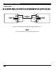
FOM LINE DRIVER—ST AND S M Application Diagram forms are found on pages 19, 21, and 23. You may be asked to fax your diagram to the Technical Support department. Use scissors to remove the page.
FOM LINE DRIVER—ST AND S M TX RX TX B A B Local Node XW2 XW1 XW1 W3 W3 W2 W2 S5 S5 W4 W4 W5 W5 W6 W6 S2 S2 S3 S3 S1: S1: 2 3 4 5 RX A Remote Node XW2 1 RX TX TX RX 6 7 8 1 2 3 4 5 6 NOTE NOTE 0 = Open or Off 1 = Closed or On 0 = Open or Off 1 = Closed or On 7 8 19
FOM LINE DRIVER—ST AND S M 20
TX RX TX B RX A B Local Node XW2 XW1 XW1 W3 W3 W2 W2 S5 S5 W4 W4 W5 W5 W6 W6 S2 S2 S3 S3 S1: S1: 2 3 4 5 RX A Remote Node XW2 1 RX TX TX 6 7 8 1 2 3 4 5 6 NOTE NOTE 0 = Open or Off 1 = Closed or On 0 = Open or Off 1 = Closed or On 7 8 21
FOM LINE DRIVER—ST AND S M 22
TX RX TX B RX A B Local Node XW2 XW1 XW1 W3 W3 W2 W2 S5 S5 W4 W4 W5 W5 W6 W6 S2 S2 S3 S3 S1: S1: 2 3 4 5 RX A Remote Node XW2 1 RX TX TX 6 7 8 1 2 3 4 5 6 NOTE NOTE 0 = Open or Off 1 = Closed or On 0 = Open or Off 1 = Closed or On 7 8 23
FOM LINE DRIVER—ST AND S M 24
FOM LINE DRIVER—ST AND S M 25
© Copyright 1998. Black Box Corporation. All rights reserved.