2.048Mbps Wireless Modem: G703: MWU2000-G703 X.21: MWU2000-X21 V.35: MWU2000-V35 Directional Antennas with 10 m of cable: 12dBi Transmit/ 12dBi Receive: MWU2000-1212 12dBi Transmit/ 18dBi Receive: MWU2000-1218 12dBi Transmit/ 24dBi Receive: MWU2000-1224 2.048Mbps Wireless Modem TECHNICAL: SALES: FAX: ADDRESS: WEB: (0118) 965 6000 (0118) 965 5100 (0118) 965 5001 464 Basingstoke Road, Reading, Berkshire RG2 0QN www.blackbox.co.
.048Mbps Wireless Modem How To Contact your Local Black Box Italy: Australia: Black Box Italia S.P.A Black Box Catalog Australia PTY LTD Tel: 0227400280 Fax: 0227400219 Web Site: www.blackbox.it Tel: 0398797100 Fax: 0398702955 Deutschland: Brazil: Black Box Deutschland Black Box Do Brasil. Tel: 0811/5541-0 Fax: 0811/5541-499 Web Site: www.blackbox-deutschland.com Tel: (011) 5515-4000 Fax: (011) 5515-4002 Web Site: www.blackbox.com.
2.048Mbps Wireless Modem France: U.S.A Black Box Catalogue Black Box Corporation Tel: 0145606700 Fax: 0145606747 Web Site: www.blackbox.fr Tel: 724-746-5500 Fax: 724-746-0746 Web Site: www.blackbox.com Spain: Chile Black Box Comunicaciones S.A. Black Box Chile Tel: 34 91 663 0200 Fax: 34 91 661 84 35 Web Site: www.blackbox.es Tel: 00 562 223 8811 Fax: 00 562 225 1002 Web Site: www.Blackbox.
2.048Mbps Wireless Modem Contents Introduction ..............................................................................................................................................8 About this Manual .......................................................................................................................8 Product Description.....................................................................................................................9 Main Features of the 2.
2.048Mbps Wireless Modem Set-up and Configuration .......................................................................................................................44 Set-up and Configuration Functions..........................................................................................44 Accessing the Set-up and Configuration Functions ..................................................................44 Main Menu .....................................................................................
2.048Mbps Wireless Modem Problem 9: The fractional E1/T1 link is synchronised, but one or some systems that are connected to the end equipment (i.e. telephone, fax voicemail) is not working properly...........................................................................................................93 Technical Specifications.........................................................................................................................95 Wireless Modem Technical Specifications.................
2.048Mbps Wireless Modem Appendix D - Installing Other Types of Receive Amplifiers ..................................................................128 General.. .................................................................................................................................128 Appendix E – Pin Assignments ............................................................................................................130 E1/T1 and Fractional E1/T1 Pin Connections ................................
2.048Mbps Wireless Modem Introduction About this Manual The following summary will help you quickly locate the information you need in this User Manual. This introductory chapter contains a description of the product, its main features, components and benefits.
2.048Mbps Wireless Modem Product Description The 2.048Mbps Wireless Modem is a high-speed full-duplex wireless modem, employing two separate RF channels for simultaneous transmission and reception of data. Using Frequency Hopping Spread Spectrum Radio Frequency modulation, the 2.048Mbps Wireless Modem permits robust and reliable wireless communication between remote sites where a physical wired connection would be impossible, impractical or too expensive. The 2.
2.048Mbps Wireless Modem Main Features of the 2.048Mbps Wireless Modem Wireless Connectivity The 2.048Mbps Wireless Modem provides a wireless data link. The DSP modem with adaptive equalization provides robust and reliable communication, overcoming problems caused by fading or interfering signals. Seamless Communication A full-duplex system with independent transmitting and receiving modems and RF channels allows seamless two-way communication. Versatility The 2.
2.048Mbps Wireless Modem RSSI Antenna reception can be fine-tuned by checking the strength of the received signal. To check signal strength, connect a Digital Voltmeter (DVM) to the Receive Signal Strength Indicator (RSSI) test point on the rear panel of the2.048Mbps Wireless Modem. Co-location This option enables to simultaneously establish a number of co-located links in star or parallel topology, when they are synchronized in frequency via a synchronizing cable.
2.048Mbps Wireless Modem Line Interface Unit The Line Interface Unit connects the 2.048Mbps Wireless Modem to the WAN or to the DTE (Data terminal Equipment). Any data, voice or video system can be connected to the 2.048Mbps Wireless Modem using standard interfaces: • T1 DSX-1 - Line code B8ZS or Bipolar AMI • E1 G703 - Line code HDB3 or Bipolar AMI • Fractional T1 DSX-1 – Line code B8ZS or Bipolar AMI • Fractional E1 G703 – Line code HDB3 or Bipolar AMI • RS-530 digital interface.
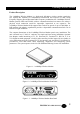
2.048Mbps Wireless Modem E1 The rear panel connector module consists of one E1/CEPT-1 balanced (RJ-45) connector and two unbalanced (2 x BNC) connectors. Fractional E1 (with Echo Cancellation) The rear panel connector module consists of one E1/CEPT-1 balanced (RJ-45) connector and two unbalanced (2 x BNC) connectors Figure 1-5. 2.048Mbps Wireless Modem Rear Panel (E1 LIU and Fractional E1 LIU) T1 The rear panel connector module consists of one T1/DSX-1 balanced (RJ-45) connector.
2.048Mbps Wireless Modem ARQ – Based Error Correction The 2.048Mbps Wireless Modem uses an Automatic Retransmission Queuing (ARQ) mechanism to detect errors in received data and to request retransmission. The use of ARQ results in a significant improvement in performance, overcoming problems caused by interfering signals. Radio Full Duplex The radio uses full duplex communication, transmitting and receiving simultaneously.
2.048Mbps Wireless Modem For further information on antennas, cables and related accessories see Chapter 2, Installation, antennas and Accessories. Antenna Interface Antenna interface to the 2.048Mbps Wireless Modem is via two SMA connectors on the rear panel; Transmit antenna should be connected to TX and Receive antenna to RX. Front Panel Indicators The front panel of the 2.
2.048Mbps Wireless Modem AIS (Alarm Indication Signal - E1/T1 and Fractional E1/T1 only). Red LED lights when WAN or DTE control frame is received by the modem indicating that information that should be sent by the modem is not received by the DTE (or the WAN). The main reason for alarm indication signal is a physical cable problem. 1. Check the cables and connectors linking the unit with the WAN or the DTE. 2. If these are OK, check WAN or DTE functionality.
2.048Mbps Wireless Modem 2.048Mbps Wireless Modem Connectors Figure 1-8 shows how to connect the 2.048Mbps Wireless Modem to its antennas, the power supply and to external equipment. Figure 1-8. 2.
2.048Mbps Wireless Modem Installation Antennas and Accessories Package Components The 2.048Mbps Wireless Modem is shipped from factory with the following components: • The 2.048Mbps Wireless Modem • Power cord (110/220 VAC models), AC connector not supplied • Monitor cable • Synchronization cable (for collocated units) • Cable adapter for DTE (V.35 and X.21 only) • This user’s guide Installing the 2.
2.048Mbps Wireless Modem Figure 2-1. 2.048Mbps Wireless Modem Rear Panel Showing 48 VDC Connector 6. For two 2.048Mbps Wireless Modems to communicate with one another, one side of the link must be configured in Master mode, with the unit at the other side of the link configured in Slave mode. Units are shipped from factory with a default setting of Slave.
2.048Mbps Wireless Modem 4. From the V.35/RS-530/X.21 Parameters menu, type 1. The Clock Rate sub-menu opens. 5. Select the required clock rate according the required data rate of n x 64kb/S. For example: • Type 1 for 64 Kbps • Type 8 for 512 Kbps (8 x 64) • Type 32 for 2048 Kbps (32 x 64) Model BL512 allows data rates up to 512 Kbps only. To Configure Channels - Fractional E1 1. From the Main menu, select 1 to access the Parameters menu. 2.
2.048Mbps Wireless Modem 4. From the Add/Remove Echo Cancellation on voice channels menu, type 2 to select the Clear (Remove) Channels menu. 5. View the current list of channel with echo cancellation. If channels in which echo cancellation should not be used are included, enter the numbers of the channels that should be removed from the list. Enter numbers between 1 to 31 separated by a comma. Use two dots to indicate a range. e.g. 2,5..7 means remove echo cancellation from channels 2, 5, 6 and 7. 6.
2.048Mbps Wireless Modem 4. From the Add/Remove Echo Cancellation on voice channels menu, type 2 to select the Clear (Remove) Channels menu. 5. View the current list of channel with echo cancellation. If channels in which echo cancellation should not be used are included, enter the numbers of the channels that should be removed from the list. Enter numbers between 1 to 31 separated by a comma. Use two dots to indicate a range. e.g. 2,5..7 means remove echo cancellation from channels 2, 5, 6 and 7. 6.
2.048Mbps Wireless Modem Figure 2-2. Basic 8.5 dBi Antenna Showing Installation screws. Medium Gain 12dBi Antenna (Uni-12) This medium gain antenna has a relatively wide beam width (22 degrees). It is intended for both indoor and outdoor installations with medium distances between sites. UNI-12 Antenna dimensions are: 15 x 15 x 38 cm. (6 x 6 x 15in.).
2.048Mbps Wireless Modem Figure 2-3. Medium Gain 12dBi Antenna Medium Gain 18dBi Antenna (Uni-18) This medium gain antenna has a medium beamwidth (14 degrees) which increases the sensitivity to inaccurate alignment, but decreases the influence of multipath propagation (fading). It is intended for outdoor installations over medium to long distances. It is probably the best choice for most medium to long range applications. UNI-18 Antenna dimensions are: 41 x 51 x 38 cm. (16 x 20 x 15 in.).
2.048Mbps Wireless Modem Figure 2-4. Medium Gain 18dBi Antenna High Gain Antenna (Uni-24) The gain of this antenna is 24dBi. It has a narrow beam width (7.5 degrees) which increases the sensitivity to alignment inaccuracy but decreases the influence of multipath propagation (fading). It is intended for outdoor installations for large distances. UNI-24 Antenna dimensions are: 61 x 91 x 38cm. (24 x 36 x 15in.).
2.048Mbps Wireless Modem Figure 2-5. High Gain 24dBi antenna.
2.048Mbps Wireless Modem Table 2-1. Antenna Characteristics RF Accessories TPA 24 Transmit Power Amplifier The TPA 24 amplifies the transmit power to a fixed output of 24 dBm (250 mW). The TPA 24 is especially useful when long RF cable runs are required. The TPA 24 also simplifies antenna alignment by enabling the use of wider dispersion transmit antennas. The TPA 24 comes in two models: TPA 24 LL and TPA 24 LH. The TPA 24 LL receives input power in the range of -10dBm to 0dBm.
2.048Mbps Wireless Modem Installing the TPA 24 1. Install the TPA 24 as close as possible to the transmitting antenna. Figure 2-6. TPA 24 Connections Diagram 2. Set the transmitter DC power supply of the 2.048Mbps Wireless Modem to 12V using the internal jumpers according to Figure 2-15: Figure 2-7.
2.048Mbps Wireless Modem Note: Installations exceeding regulations set by local authorities expose the installer and the user to potential legal and financial liabilities. LNA-10 Low Noise Receive Amplifier The LNA-10 is a high-performance, low-noise preamplifier designed to enhance fringe area reception and to provide additional gain on the receive antenna, especially when using long cable runs.
2.048Mbps Wireless Modem NF2 = Noise Figure of the cable = Loss of cable NF3 = Noise Figure of the modem = 2.8 G1 = Gain of LNA 10 = 10 G2 = Gain of the cable = 1/Loss of cable (*) All values above are taken in absolute value (not dB). Use the following table to quickly determine the improvement of the LNA, given different cable-loss. For convenience, the "LNA Improvement" value is converted to logarithmic values (dB). Table 2-2.
2.048Mbps Wireless Modem Figure 2-9. LNA-10 Cable Connection Diagram The power supply (PS) and Power Inserter are supplied with the LNA-10. The RG-59 coaxial cable (with F-type connector) is not supplied and must be purchased separately. Note: See Appendix C for installing other types of receive amplifiers AL-1 Lightning Arrestor The AL-1 Lightning Arrestor is used to protect transmitters and receivers from transients originating from lightning or EMP. The AL-1 is gas tube-based and is not radioactive.
2.048Mbps Wireless Modem Figure 2-10. AL-1 Cable Connection Diagram Cable Types Thin Cable This is a relatively thin and flexible cable. However, its attenuation is relatively high. Impedance is 50W. Outer diameter is 5mm (0.195"). Thick Cable This cable is thicker, heavier and less flexible than the thin cable. However, its attenuation is less than that of the thin cable. Impedance is 50W. Outer diameter is 10.8mm (0.425"). Low Loss Cable This cable is thicker, heavier and more expensive.
2.048Mbps Wireless Modem Professional Installers Only Antennas, whether installed indoors or out, are to be installed ONLY by experienced antenna installers that are familiar with local buildings and safety codes, and wherever necessary are licensed by appropriate government regulators. Failure to do so may void the Product Warranty and will certainly expose the end user to legal and financial liabilities.
2.048Mbps Wireless Modem Figure 2-12.
2.048Mbps Wireless Modem Range Tables Use the following tables to calculate the antennas and cables that will best suit your transmit/receive range requirements (assuming line-of-sight between 2.048Mbps Wireless Modem Master and Slave units). The tables are based on the assumption that the default modem rate is being used. If a modem rate higher than the default rate is being used, the achievable range should be estimated according to the actual modem rate.
2.048Mbps Wireless Modem Table 2-6. Maximum (Unregulated) Range Table Antenna Alignment In order to function properly and to provide quality results, the modems on either side of the link must have a stable RF link. The alignment procedure is performed in three steps. First, you visually align the antennas on both sides of the link. Next, you activate the Radio and Line LEDs on the front panels of the units (which show basic synchronization) by a process of adjusting the antennas.
2.048Mbps Wireless Modem To activate the front panel LEDs: 1. If the LEDs are not lit, loosen the screws on the U-bolt that fasten the Rx and Tx antennas to the last (or the bolts on the wall mount) and slowly move the antennas up and down (elevation) and from side-to-side (azimuth), until all four LEDs are lit (Radio - RX Sync and TX Sync, Line –RXD and TXD). 2. Tighten the screws on the U-bolt (or the bolts on the wall mount).
2.048Mbps Wireless Modem 2. Loosen the screws on the U-bolt that fasten the receive antenna to the mast (or the bolts on the wall mount) and slowly move the antenna up and down (elevation) and from side-to-side (azimuth) until you receive a maximum RSSI reading on the DVM. (See Figure 2-15). 3. Tighten the screws on the U-bolt (or the bolts on the wall mount). Figure 2-15. RSSI test point accuracy.
2.048Mbps Wireless Modem Figure 2-17. Jumper Setting for RSSI measurement via the Receive RF Cable 3. Connect a DVM to the DC port of the Bias-T. 4. Loosen the screws on the U-bolt that fasten the receive antenna to the mast (or the bolts on the wall mount) and slowly move the antenna up and down (elevation) and from side-to-side (azimuth), until you get a maximum RSSI reading on the DVM. 5. Tighten the screws on the U-bolt (or the bolts on the wall mount).
2.048Mbps Wireless Modem Figure 2-18. Default position (NC) of the Jumpers in the Receive Module. Synchronizing Co-located Modem Units When two or more 2.048Mbps Wireless Modem units are co-located, you should perform the following procedures in order to allow optimal performance. These procedures enable synchronization of the hopping sequences used by the links, and ensure sufficient separation between frequencies used by the links at any given time.
2.048Mbps Wireless Modem Figure 2-19. Several Co-located modems in a “star” configuration Note: On the Master side, the 2.048Mbps Wireless Modem units with a SW version 1.6 and up and HW version 2 must be used. On the Slave side, 2.048Mbps Wireless Modem units with a SW version 1.6 and up can be used with either HW version 2 or previous HW version. Step-1: Installing the Antennas Install the antennas of the co-located units to minimize interference.
2.048Mbps Wireless Modem • Set “Number of links to synchronize” to a value greater or equal to the actual number of connected links. This setting is not necessary for the “Slave” units. Note: Selecting the option “Synchronize as many links as possible” may result in less than optimal performance. Use this option only in situations where co-located links are added and/or deleted frequently. • Use the following table to determine the maximum number of links to synchronize: Table 2-7.
2.048Mbps Wireless Modem Figure 2-20. Several Co-located 2.048Mbps Wireless Modems in a “center-to-center” configuration. Step-3 Connecting the Master units Establishing synchronization is a “Hot Plug-In” process: You can add a new link without interfering with the normal operation of the working link(s), provided the relevant parameters are properly set (as described above). Figure 2-21.
2.048Mbps Wireless Modem Set-up and Configuration Set-up and Configuration Functions This section explains how to access and set the Set-up and Configuration functions that are provided for the 2.048Mbps Wireless Modem.
2.048Mbps Wireless Modem Figure 3-1. Main Menu Note: Hardware version 2 includes all features of Hardware version 1, plus co-location support through synchronization and RSSI test point.
2.048Mbps Wireless Modem System Reset Resetting the system from the System Reset menu implements all the changes made to the parameters of all the Setup and Configuration functions. Testing This menu is for authorized Black Box technical staff only. Parameters Menu You can access most of the items for configuring your 2.048Mbps Wireless Modem from the parameters Menu: To access the Parameters Menu: • In the Main menu, at the Select Option prompt, type 1. The Parameters menu appears.
2.048Mbps Wireless Modem 2. Press Esc at any stage to return to the previous menu (if you press Esc before making any selection, the message: Loading cancelled, old value retained appears). Note: You can operate all the Setup and Configuration sub-menus by using these procedures and by following the instructions on the screens. LIU Parameters Menu The LIU Parameters menu gives you access to the following sub-menus: • E1 Parameters Menu (select if an E1 LIU is used).
2.048Mbps Wireless Modem E1 Alarm Buffer The Possible alarms are: • LOS (all zeros signal): Loss Of Signal – No signal is received from the data equipment. • AIS: Alarm Indication Signal – No signal is received by the connected end equipment. When an alarm is detected, a note appears at the bottom of the display (Note: An alarm has been activated), and the message ALARM EXISTS is displayed on the menu header (see Figure 3-1). In addition, the TEST LED will blink.
2.048Mbps Wireless Modem Table 3-2. Fractional E1 parameters Menu Items and Actions Remote Alarm Method Two methods may be used to indicate to the end equipment of an alarm condition following loss of synchronization: • Bit 3 of TS (Time Slot) 0: Under normal conditions, this bit is always set to 0. Upon identification of an alarm condition, it is set to 1.
2.048Mbps Wireless Modem Long haul/Short haul This parameter determines the sensitivity of the receiver circuits in the line interface to the end equipment. If the distance between modem and the end equipment is up to 500 meters, it should be set to 0 (short haul). If the distance is more than 500 meters, it should be set to 1 (long haul) to compensate for losses by increasing the sensitivity of the receiver circuits by approximately 30 dB.
2.048Mbps Wireless Modem Remote-BreezeLINK-Unsync Indicates a temporary incidence of a very noisy radio channel. Repeated occurrences indicate either a very noisy radio channel or a hardware problem (e.g. clocks with excessive jitter) or a problem related to configuration of clocks. Too many BPV/CV Too many Bipolar code violations, indicates selection of Bipolar AMI line code in the modem when the end equipment uses HDB3 line code.
2.048Mbps Wireless Modem When an alarm is detected, a note appears at the bottom of the display (Note: An alarm has been activated) and the message: ALARM EXISTS is displayed on the menu header (see Figure 3-1). In addition, the TEST LED will blink. Fractional T1 Parameters Menu See also Appendix C.
2.
2.
2.048Mbps Wireless Modem Superframe Method Each frame transmitted to (or received from) the end equipment is comprised of 193 bits, numbered 1 to 193. Bit numbers 2 to 193 are used for data. The first bit of each frame is designated an F-bit, and is used for purposes such as frame alignment, performance monitoring (CRC check) and providing a data link. There are two alternative methods for allocation of F-bits: • ESF: A 24-frame multiframe.
2.048Mbps Wireless Modem interface, as per the requirement specified in the applicable standard (DSX-1 for DSU network interface, ANSI T1.403 for CSU network interface). See Appendix C for more details about CSU and DSU network interfaces. CRC6 Usage The F-bits in an ESF multiframe (see Superframe method above) provide Cyclic Redundancy Check 6 (CRC6) information. These bits are the result of a certain calculation performed on all the bits of the previous multiframe (24 frames).
2.048Mbps Wireless Modem • Straight 2100Hz tone (0): The most popular method based on transmitting a straight 2100Hz tone. • Phase reversed 2100Hz tone (1): A 2100Hz tone with phase reversals for improved differentiation from voice signals. • 2100Hz VPA tone (2): A tone in the range 2000-2100Hz. Fractional T1 Alarm buffer The possible alarms are: LOS (Loss Of Signal): Also referred to as all zeros signal, indicates that no signal is received from the data equipment.
2.048Mbps Wireless Modem V.35/RS530/X.21 Parameter Menu Table 3-5. V.35/RS-530/X.21 Parameters Menu Items and Actions DCE/DTE The current selection is displayed (or a “NOT DEFINED message, if a different LIU is used). Table 3-6 displays DCE/DTE functionality options: Table 3-6.
2.048Mbps Wireless Modem See Appendix A for details on DCE/DTE options and for instructions on setting the LIU jumpers according to the end equipment configuration. Unless specially ordered, the 2.048Mbps Wireless Modem with a V.35 or RS-530/X.21 LIU is supplied from the factory with the settings DCE, internal clock. Clock Polarity The current selection is displayed (or a NOT DEFINED message, if a different LIU is used).
2.048Mbps Wireless Modem For fractional E1/T1, the LIU card performs the loopback. Both clock and data are looped back. When the Master modem is set for loopback operation, the clock starts drifting from the clock of the end equipment (under normal conditions, the system clock is supplied by the Master end equipment). Eventually this will lead to error messages and the link will be disconnected.
2.048Mbps Wireless Modem Table 3-9. MCP Parameters Menu Options Master-Slave In synchronous data communications systems, all components of the link should operate using the same clock. The Master unit provides the clock and the Slave unit reconstructs it from the data received from the master unit. Total Link Delay In order to improve performance the 2.
2.048Mbps Wireless Modem In order to maintain a continuous flow of reconstructed received data transferred to the terminal equipment, a delay must be introduced. The longer the delay, the more effective the ARQ mechanism. A longer delay can improve performance in applications not sensitive to delay. The same delay settings must be configured on both Master and Slave modems. In voice applications, select the maximum acceptable delay. It is recommended to use an echo canceller.
2.048Mbps Wireless Modem The following commands are set as a default initialisation string in the modem: AT&f\n The meaning of this string is initialising default configuration (“n” means “new line”). An example for a more informative initialisation string is: AT&f\nATS0=1\nAT&K0\nATS23=3B\nATQ1\n This default string is consistent with a few modem types, for example MICROCOM desktop. The meaning of the above string is as follows: • AT&T – Initialise default configuration.
2.048Mbps Wireless Modem Radio and Modem Parameters Menu The Radio and Modem Parameters menu gives you access to the following parameters: • Modem Rate • Hopping Sequence • Transmit Power • Test Sequence Add/Remove Channels menu Table 3-10. Radio and Modem Parameters Menu Options Modem Rate The modem rate is set automatically according to the selected LIU Data Rate (Clock Rate), according to the following table: Table 3-11.
2.048Mbps Wireless Modem Changing the modem rate above the default value results in the following: • The higher the modem rate, the lower the sensitivity. Achievable distances decrease as the modem rate increases. • The higher the modem rate relative to the LIU data rate, the higher the effective bandwidth. Better use is made of the frequency diversity capability inherent to the frequency hopping mechanism.
2.048Mbps Wireless Modem • Copy local database and download to remote unit. Table 3-12. REMOTE Parameters Menu Options Switch to Remote Monitor When selecting option 1 (Switch to remote monitor) in the REMOTE Parameters Menu, the database of the remote unit starts loading into the local unit. This process takes some time, and the time required is even longer if the quality of the link is poor. Once the remote database is loaded, you can view or change the parameters of the remote unit.
2.048Mbps Wireless Modem Ping Remote Unit The remote management process involves transfer of large quantities of data between the units, in addition to normal data and signals. Since this transfer can take a long time, the PING mode is used to verify that there is a working link between the two units and that remote management operation is feasible.
2.048Mbps Wireless Modem Table 3-13. Load Default Values Menu options Note: The Hopping Standard and LIU type parameters are fixed and are not affected by this operation. Parameter Info. Screen Option 6 in the Parameters menu opens the Info Screen, which presents information on the current status of main parameters of either the local or the remote unit (depending on local/remote monitoring status). Press any key to return to the Parameters menu. Figure 3-5.
2.048Mbps Wireless Modem Counters and Tracers Menu To access the Counters and Tracers Menu: • From the Main Menu, type 2. The Counters and Tracers Menu appears.
2.048Mbps Wireless Modem System Counters In the Counters and Tracers menu, type 1 to display the System Counters. LIU TX BUFFERS LIU RX BUFFERS# LIU ERROR BUFFERS LIU BUFFER ERROR RATE RADIO NOT ACK BUFFERS RADIO TX BUFFERS RADIO RX BUFFERS RADIO ERROR BUFFERS RADIO NO RX BUFFERS RADIO BUFFER ERROR Rate Hit any key > 0 0 0 0.00e+00 0 70321 0 0 0 0.00e+00 Figure 3-7.2.048Mbps Wireless Modems Counter display.
2.048Mbps Wireless Modem The following is a table of the buffers and their description: Table 3-14. Buffers Name and Description • Under normal conditions, the number of LIU TX BUFFERS is approximately (±2) equal to the number of LIU RX BUFFERS. • Under normal conditions, communication with the end equipment is not subject to any interruptions, and LIU ERROR BUFFERS as well as the LIU BUFFERS ERROR RATE should be 0. Note: Buffer Error Rate is different from Bit Error Rate.
2.048Mbps Wireless Modem Table 3-15. Modem Rate Vs. Buffer Size • A high number of RADIO NO RX BUFFERS that are relative to the number of the RADIO ERROR BUFFERS indicates the existence of problems in one or more frequency channels. • It is recommended to have RADIO BUFFERS ERROR RATE under 2% (2e-2). High error rate indicates bad reception conditions. High error rate combined with a relatively high number of not received buffers indicates weak radio signal or existence of an interfering signal source.
2.048Mbps Wireless Modem The RSSI per channel test displays in graphic format the strength of the received signal on each of the RF channels used by the 2.048Mbps Wireless Modem. Each vertical column represents the level of the received RF signal on one of the channels. Available channels are from 0 to 100 (0 representing 2.400GHZ and 100 representing 2.500GHz), depending on hopping sequence setting.
2.048Mbps Wireless Modem Each column represents the percent of RADIO ERROR BUFFERS in each of the RF channels, out of all the buffers that were transmitted on the channel. A “–” sign at the bottom represents a channel that is not included in the set of hopping frequencies. On top of the graph, information is provided on the channel with the highest error rate (Max errors in percentage and the number of the channel with the maximum error rate).
2.048Mbps Wireless Modem Figure 3-12. Time Tracer Max Consecutive Errors Graph Using the same time resolution as the Time Tracer Errors versus Time, this graph displays the maximum number of consecutive errors in each time unit. At the top of the graph appears information on the maximum number of consecutive errors identified during the tracing period, and how much time passed since this event. Each column in the graph represents the relative number of consecutive errors in the relevant time period.
2.048Mbps Wireless Modem 2. Select a new resolution. You can enter up to 11 characters in hh:mm:ss.ss format. For example, to display a tracer of 69 minutes, set the Time Tracer resolution to 00:01:00.0. Note: Each time you define a new resolution; the time tracer graphs are reset. Reset Counters In the Counters and Tracers menu, type 8 to view the Reset Counters.
2.048Mbps Wireless Modem Watch Alarms Alarms for V1.7 LIU Alarms In the Counters and Tracers menu, type A to display the alarms of the monitored unit Message: Input CLK to LIU is 0 Description: Appears in a unit with V.35/RS-530/X.21 hardware that is configured in software as an E1/T1 unit. Correction: Select the correct LIU type in the LIU parameters menu. Message: LOS (all zeros signal) Description: Indicates an all zeros signal to an E1/T1 or a Fractional E1/T1 LIU.
2.048Mbps Wireless Modem Message: Remote Frame Alarm Description: In fractional E1 applications, an indication from the connected end equipment that it was unsuccessful in synchronizing with the 2.048Mbps Wireless Modem. Correction: Check the cable, which connects the end equipment to the modem. Message: Yellow-alarm Description: In fractional T1 applications, an indication from the connected end equipment that it was unsuccessful in synchronizing with the 2.048Mbps Wireless Modem.
2.048Mbps Wireless Modem Message: RLOS (framer un-synchronized) Description: In Fractional T1 applications, the wireless modem was unsuccessful in synchronizing with the end equipment. Correction: Check the cable that connects the end equipment to the modem. Check that parameters of the modem and end equipment match each other (e.g. framing method and line coding).
2.048Mbps Wireless Modem Message: WARNING: Delay setting may be too short to correct all errors Description: The selected delay setting might be too short to allow the ARQ to correct the bursts of radio errors present. Correction: Increase the delay setting or identify and eliminate the cause of the bursts by using the tracers.
2.048Mbps Wireless Modem Message: WARNING: Net I.D. too high (relevant only regarding synchronization) Description: The Net I.D. for a link that should be synchronized is higher that the requested number of links to synchronize. Correction: Adjust the Net I.D. Message: WARNING: Difference in parameter(s) between two units Description: Different setting of parameters in the two units forming the links.
2.048Mbps Wireless Modem Mode and Access Control Menu The Mode and Access Control menu enables to define the access rights. It also enables access to the Site Survey Mode for surveying the applicable electromagnetic environment of the site (this does not require a password). Mode and Access menu ==================== 1 - Change Access Rights 2 - Enter Site Survey Mode (System Reset) 3 - Exit Site Survey Mode (System Reset) Figure 3-13.
2.048Mbps Wireless Modem Figure 3-14. Site Survey Graph The minimum measurable RSSI of the system is approximately -103 dBm. An RSSI level higher than -103 indicates interference. The difference between the level of interference to 103 dBm affects the sensitivity in that frequency. In the above graph, the channel with the most interferences (channel 46) has the maximum RSSI level of -94 dBm, while the minimal RSSI level of the system is -103 dBm. The difference is 9 dB.
2.048Mbps Wireless Modem Troubleshooting Introduction In the process of establishing a link, various problems may arise, either single link problems or co-located link problems.
2.048Mbps Wireless Modem ⇒ To check the configuration of each unit: 1. From the Parameters menu, select Parameters Info. Screen. 2. Verify that one unit is configured as Master and the other as Slave. 3. Verify that the following parameters are set identically on both units: • Network I.D. • Hopping Standard and Hopping Sequence • Modem Rate ⇒ To check RF Installation: • Verify that the TX and RX cables are connected correctly, and that the antennas are aligned. • Check the TX radio High/Low power setting.
2.048Mbps Wireless Modem The received power should be above the reception threshold for the modem rate in use. It is preferable to keep the received power level at least 10 dB above the threshold for an adequate fade margin. If the received power level is not sufficient, check RF installation and increase the antenna gain, use cables with lower loss or add a Transmit Power Amplifier or an LNA. 7. Type 3 (Display Channel Tracer errors per channel) to check packet error rate.
2.048Mbps Wireless Modem 3. For X.21, RS-530 and V.35 configured as DCE External Clock or DTE, verify that: • The end equipment is defined as DTE or DCE accordingly. • The end equipment is connected to the unit. • In the Counters and Tracers menu select Watch Alarms. Verify that the alarm monitor checks that the clock rate setting of the end equipment matches the clock rate setting of the unit. 4. For Fractional E1: • Verify that the line coding selected (HDB3/AMI) matches the setting of the end equipment.
2.048Mbps Wireless Modem 2. For X.21, RS-530 and V.35, verify that: • The DCE Internal clock or DCE External clock or DTE setting on each unit is matched by the DCE/DTE configuration of the end equipment. • The clock rate setting of the end equipment matches the clock rate setting of the unit. 3. For E1, T1, Fractional E1, Fractional T1 verify that: • The line coding scheme used by the 2.048Mbps Wireless Modem and the end equipment are the same.
2.048Mbps Wireless Modem • For E1 and Fractional E1, verify that the balanced/unbalanced configuration of the LIU (set by the jumpers on the LIU board) matches that of the end equipment. Problem 6: The radio link is fine, but the voice quality/data rate is poor, or the end equipment loses synchronization from time to time. Probable cause: • There is an echo on the voice channels created by the end equipment.
2.
2.
2.048Mbps Wireless Modem Table 4-1. Error Messages Source Problem 8: One or more links function properly (are synchronised), but when adding another link, performance degrades. Probable cause: • Incorrect configuration of all units connected by the synchronization cable. • Physical problems with the synchronization cable. ⇒ To check the configuration of each unit: 1. In the Counters and Tracers menu select Watch Alarms and make sure no alarms regarding synchronization are present. 2.
2.048Mbps Wireless Modem 4. Verify that the following parameters are the same in both units: • Hopping Standard and Hopping Sequence • Clock Rate and Modem Rate 5. Check that the number of links to synchronize parameter is greater or equal to the number of connected units. Problem 9: The fractional E1/T1 link is synchronised, but one or some systems that are connected to the end equipment (i.e. telephone, fax voicemail) is not working properly.
2.048Mbps Wireless Modem 3. Check that the error rate of the LIU link is not too high. It is recommended that the LIU BUFFER ERROR RATE should not exceed 10-5. Contact Black Box Should you still have problems, contact your local Black Box. All of the phone numbers are listed at the front of this manual.
2.048Mbps Wireless Modem Technical Specifications Wireless Modem Technical Specifications Models 2.048Mbps Wireless Modem For data rates of up to 2.048 Mbps, with E1, T1, RS-530, V.35 or X.21 interface 512Kbps Wireless Modem For data rates of up to 512kbps, with RS-530, V.35 or X.21 interface. Call Black Box for a quote for this model. Radio and Modem Specifications Radio Type Full duplex point to point, independent transmit and receive radio channels.
2.048Mbps Wireless Modem The modem rate is selected automatically by the selected LIU Data Rate (Clock Rate), according to the following table: Table 5-2. Default Modem Rate According to Selected LIU Data Rate Channel Bandwidth The bandwidth for each channel is –20dBc at ±500KHz from carrier, regardless of bit rate. System Bandwidth 2400-2500MHz. Different frequency bandwidth is available according to the different country standards. Table 5-3.
2.048Mbps Wireless Modem Maximum Spurious Level 60dBc Receiver Sensitivity The receiver sensitivity, as a function of the radio BER, is determined according to Table 5-4. Note that the radio error rate does not include the error correction algorithm, which can improve sensitivity by up to 3dB, depending on the settings of the unit. Table 5-4. Receiver Sensitivity as a Function of the Radio BER Receiver Sensitivity • Retransmission of packets with errors. • Elastic buffer to maintain continuous data flow.
2.048Mbps Wireless Modem Figure 5-1. Radio BER Improvement Table 5-5. System Gain Maximum Receive Level -10dBm for modem rates: 0.5Mbps, 1Mbps, 2Mbps. -25dBm for modem rate of 3Mbps. Recommended Receive Level 10dB above sensitivity threshold for an adequate fade margin.
2.048Mbps Wireless Modem causes a degradation of 3db in the sensitivity of the receiver. The graph below displays the adjacent channel rejection of the modem receiver as a function of the frequency separation (Delta F in MHz) between the frequency of the interfering signal and the desired signal. Figure 5-2. Adjacent Channel Rejection Separate between TX and RX frequencies Minimum 12MHz for sensitivity degradation of 1dB.
2.048Mbps Wireless Modem Maximum Number of Links to Synchronize Table 5-6. Maximum Number of Synchronized Links Filter Curves Filter curves for the transmitter and receiver are shown in the graph below. Note that the receiver contains two cascaded filters of this type. Figure 5-3. Filter Curves.
2.048Mbps Wireless Modem Frequency Accuracy ±15ppm. Noise Figure 5dB max. Total Link Display Controllable, between 14ms to 156ms, depending on the Data and Radio rates. Line Interface Specifications Data Rates (Full Duplex) Nx64Kbps: 64, 128, … 2048kbps N x 64Kbps: 64, 128, … 2048 Kbps. LIU Options T1 Interface Data Rate: 1544 Kbps Type: DSX-1, meets CCITT G.703 and G.
2.048Mbps Wireless Modem Fractional T1 Interface Data Rate: 1544 Kbps Type: DSX-1, meets CCITT G.703, G.704 and G.823 Connector: RJ-45 Line Mode: Bipolar AMI or B8ZS Impedance: 100Ω Fractional E1 Interface Data Rate: 2048 Kbps Type: CEPT-I, meets CCITT G.703, G.704 and G.823 Connector: 2 x BNC (unbalanced), RJ-45 (balanced) Line: Code HDB3 or AMI Impedance: 75Ω (unbalanced), 120Ω (balanced) V.35 Interface Data Rate: 64 - 2048 Kbps (N x 64) Type: Synchronous Data, V.
2.048Mbps Wireless Modem X.21 Interface Data Rate: 64 - 2048 Kbps (N x 64) Type: Synchronous Data, RS-422 levels Connector: D-type, 15 pins, female (An adapter cable connected to the 25 pins D-Type connector on the RS-530/X.21 LIU) Echo Canceller (Fractional E1/T1) Meets ITU-T recommendations G.165 and G.
2.048Mbps Wireless Modem Q-CTRL (future option) RJ-45, 8 pin, female RSSI Test point (for DVM), accuracy = ±20%. Power 100 - 240 VAC or 18 - 72 VDC, 25 W max. Management Monitoring, diagnostics and configuration. Interface - V.24/RS-232, 9 pins D Type female connector. Access using a locally connected ASCII terminal or remotely via dial-up modem. Remote unit management, through the wireless link. Mechanical Specifications Dimensions Standard 1U half 19” 7.7” x 9.6” x 1.
2.048Mbps Wireless Modem Antennas Sets One transmit antenna, one receive antenna. Standard Antennas: • low - 8.5dBi, 8.5dBi. • Basic – 12 dBi, 12dBi • Medium Gain - 12dBi, 18dBi. • High Gain – 12, 24dBi. TPA 24 Technical Specifications Models used with 2.048Mbps Wireless Modem: TPA 24 LH.
2.048Mbps Wireless Modem Connectors LNA 10 • RF IN: N-type, female • RF OUT: N-type, male • Signal and Power IN: not in use • Signal and Power OUT: F-type, female Power Inserter • To CONV: F-type, female • To TV: F-type, female (not in use) Power Supply Required Voltage: +12V to +28Vdc Required Current: 20mA Operating Temperature: Dimensions: -20°C to +50°C 60mm x 35mm x 25mm (2.3”x 1.
2.048Mbps Wireless Modem Operating Environment: Indoor/Outdoor Grounding: One of the female-type N connectors is mounted directly through a hole in the shelter wall and held in place with a lockwasher and nut.
2.048Mbps Wireless Modem Appendix A - V.35/RS-530/X.21 Applications DCE/DTE Configuration The following is a description of the possible configurations when connecting V.35/RS530/X.21 end equipment to the 2.048Mbps Wireless Modem. The configurations described are applicable to software version 1.5 and up with a V.35/RS-530/X.21 LIU equipped with jumpers for setting the mode of operation. V.35/RS-530/X.
2.048Mbps Wireless Modem Table A-2. Configuration * Slave can also be configured as DCE with external clock provided that the external clock supplied by the DTE is identical to the clock supplied by the 2.048Mbps Wireless Modem Standard Configuration Figure A-1. Standard modem Application • Both wireless modem units are configured as DCE, internal clock. • Either unit A or B can be defined as the Master unit. Synchronizing your Modem to Another Network Figure A-2.
2.048Mbps Wireless Modem • DTE A supplies the Master clock. • Modem A is configured as “Master”, DCE external clock. • Modem B is configured as “Slave”, DCE internal clock. Connecting your 2.048Mbps Wireless Modem to another modem Figure A-3. Modem configured as DCE • Modem A is defined as a DCE. It supplies the clock for the 2.048Mbps Wireless Modems. • 2.048Mbps Wireless Modem A is configured as “Master”, DTE (except in applications with an X.21 interface). • 2.
2.048Mbps Wireless Modem DCE Options 1. DCE, internal clock - Supported by V.35, RS-530 and X.21. Jumper configuration: Figure A-5. DCE, Internal Clock Jumpers 2. DCE, external clock - Supported by V.35 and RS-530. Jumper configuration: Figure A-6.
2.048Mbps Wireless Modem DTE Options 1. DTE - Supported by V.35, RS-530. Jumper configuration: Figure A-7. DTE, V.35 and RS-530 2. DTE - Supported by X.21. Jumper configuration: Figure A-8. DTE, X.21 Setting the DCE/DTE Mode Parameter To set the DCE/DTE mode: 1. From the Setup and Configuration Main menu, type 1 to access the Parameters menu. 2. From the Parameters menu, type 1 to access the LIU Parameters menu. 3. From the LIU Parameters menu, type 5 to access theV.35/RS-530/X.21 menu. 4. From the V.
2.048Mbps Wireless Modem • Type 3 for DTE (X.21) mode Valid selections are in accordance with following guidelines: • DCE internal clock (V.35 & Rs-530 & X.21)- Supported by V.35, RS-530and X.21 • DCE external clock (V.35 & RS-530)- Supported by V.35 and RS-530 • DTE (V.35 & RS-530) - Supported by V.35, RS-530 • DTE (X.21) - Supported by X.21.
2.048Mbps Wireless Modem Appendix B - E1 / T1 Applications Introduction This appendix describes some of the possible ways to connect an E1/T1 Wireless Modem to E1/T1 end equipment. For each possible connection, the indications given by the 2.048Mbps Wireless Modem unit and the expected end equipment behaviour are described. The RJ-45 balanced four-wire interface is also discussed. The second part of this appendix provides information about E1/T1 LIU board jumper settings.
2.048Mbps Wireless Modem Table B- 1. E1/T1 Connections In addition to the faults mentioned in the above table, there is a possibility of a cable being disconnected or shortened. Both these situations usually result in LOS indication either by the modem or by the end equipment. E1/T1 LIU Jumper Settings The LIU default setting is E1 balanced or T1 balanced, unless an E1 unbalanced configuration is specified.
2.048Mbps Wireless Modem Figure B-2. E1/T1 Board Location To access the jumpers: 1. Disconnect all cables, including the power cable, from the unit. 2. Loosen and remove the two screws on the rear panel. Carefully slide out the boards. The jumpers are located at the bottom side of the LIU board shown in Figure B-3. 3. Turn the boards over, loosen and remove the three screws connecting the LIU board to the main board. 4. Unscrew and remove the nuts and the spring washers from the Tx and Rx connectors.
2.048Mbps Wireless Modem Figure B-3. E1 Unbalanced (Coax connector, 75 W) Figure B-4. E1 balanced (RJ-45 connector, 120 W) Figure B-5.
2.048Mbps Wireless Modem T1 CSU/DSU Applications In most T1 applications, the 2.048Mbps Wireless Modem replaces the CSU/DSU (or OCU) used in regular wired connections. Figure B-6. T1/DSU Network Interface This type of connection is referred to as “DSU network connection”. In order to meet the applicable pulse mask requirements of the DSX-1 standard, the Pulse Shape Parameter should be set according to the line length. Figure B-7.
2.048Mbps Wireless Modem E1/T1 Back-to-Back Configuration Figure B-8.
2.048Mbps Wireless Modem Appendix C – Fractional E1/T1 Applications Introduction This appendix explains under which conditions it is recommended to use the Fractional E1/T1 LIU. It also describes some of the possible ways to connect a Fractional E1/T1 2.048Mbps Wireless Modem to Fractional E1/T1 end equipment. For each possible connection, the indications given by the modem unit and the expected end equipment behaviour are described. The RJ-45 balanced four-wire interface is also discussed.
2.048Mbps Wireless Modem The following table provide details on effective data rate and default modem rate for Fractional E1/T1 applications. In general, effective data rate for N used channels is (N+1) x 64 Kbps. For example, if the user needs 8 channels, the modem will effectively transmit a data rate of (8+1)*64 = 576Kbps. In fractional T1 applications, the modem will add a full 64Kbps channel for signalling. The maximal data rate of the modem for a 24 channel T1 is therefore 1600Kbps, vs.
2.048Mbps Wireless Modem Table C-2 summarizes the possible connections and the resulting behaviour: Table C-2. Fractional E1/T1 Connections In addition to the faults mentioned in the above table, there is a possibility of a cable being disconnected or shortened. Both these situations usually result in LOS indication either by the 2.048Mbps Wireless Modem or by the end equipment.
2.048Mbps Wireless Modem Figure C-2. Fractional E1 Board Location To access the jumpers: 1. Disconnect all cables, including the power cable, from the unit. 2. Loosen and remove the two screws on the rear panel. Carefully slide out the boards. The jumpers are located at the upper side of the LIU board shown in Figure C-3. 3. Set the jumpers according to diagrams C-3 to C-4.
2.048Mbps Wireless Modem Figure C-3. Fractional E1 Unbalanced (Coax connector, 75 W) Figure C-4.
2.048Mbps Wireless Modem Fractional T1 CSU/DSU Applications • In most Fractional T1 applications, the 2.048Mbps Wireless Modem replaces the CSU/DSU (or OCU) used in regular wired connections. Figure C-5. Fractional T1/DSU Network Interface This type of connection is referred to as a DSU network connection. In order to meet the applicable pulse mask requirements of the DSX-1 standard, the Pulse Shape Parameter should be set according to the line length (option 1 to 5). Figure C-6.
2.048Mbps Wireless Modem Fractional E1/T1 Back-to-Back Configuration Figure C-7. Fractional E1/T1 Back-to-Back Configuration Echo Cancellation in Fractional E1/T1 Applications Regular telephony systems use 4 wires circuits: one pair for the transmitted signal (microphone) and one pair for the received signal (earphone). The transmission system is comprised of a single pair (2 wires) and a hybrid component used for the required conversion from 4- to 2-wires and vice versa.
2.048Mbps Wireless Modem Echo cancellers circuits are used in long distance and some wireless links to solve the echo problem. The operation of echo cancellers is based on estimation of the interfering echo signal that is added to the desired signal and subtraction of a similar signal, thus cancelling or significantly reducing the interfering echo signal. Regular voice channels are used in many applications for modem and fax communications.
2.048Mbps Wireless Modem Appendix D - Installing Other Types of Receive Amplifiers General The 2.048Mbps Wireless Modem supports other types of Receive Amplifiers which are not supplied by Black Box. Following are some tips regarding installation of different types of Receive Amplifiers. The installation of other types of Receive Amplifiers is usually similar to the installation of the LNA-10. 2.048Mbps Wireless Modem can be set to provide 12 VDC power via the Receive RF cable.
2.048Mbps Wireless Modem Figure D-2. Jumper Setting for 12 VDC Power Supply To supply DC input through the RF cable 1. Connect the RF + Power Cable directly to the RF input in the Receive Amplifier. 2. Set the jumper Jp1 in the Rx Radio module to 12 VDC. Figure D-3.
2.048Mbps Wireless Modem Appendix E – Pin Assignments E1/T1 and Fractional E1/T1 Pin Connections Table E-1. E1/T1 and Fractional E1/T1 Pin Connections LIU RS-530 Connector Pin Assignments Figure E-1. LIU RS-530 Pin Assignments.
2.048Mbps Wireless Modem LIU D-25 to V.35 Cable Pin Assignments Figure E-2. LIU D-25 to V.35 Cable Pin Assignments.
2.048Mbps Wireless Modem LIU D-25 to X.21 Cable Pin Assignments Figure E-3. LIU D-25 to X.