
Specifications

724-746-5500 | blackbox.com
Page 18
NBS008A
724-746-5500 | blackbox.com
Chapter 5: Operation
5. Operation
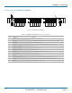
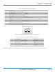
The switch contains 4, 6, 8 or 16 switch circuits (ports) depending on model. When power is applied to the unit, the appropriate
power supply status indicators (PS1 and/or PS2) will light. The switch position indicators (A and B) on the front of the unit may or
may not light depending on the position of the switch ports. Indicator A lights when all ports are in position A (each A port from
“1” to “N” is connected to its respective COMMON port “1” through “N”), and likewise for indicator B. If some switch ports are
in position A and some in position B then neither LED will be on. The switches connect the COMMON ports to either A ports or
B ports. Selecting port A (OFF) disconnects COMMON ports from B ports, selecting port B (ON) connects COMMON ports to B
ports.
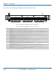
For fiber optic models, the switch uses duplex connections for each channel (port). One duplex SC connector per port form a
bidirectional data path, with COMMON port 1 switched to A port 1 or B port 1). Likewise, COMMON port 2 is switched to A
port 2 or B port 2.
NOTE: All switch fiber optic connections are straight-through for each port. Be sure to connect the fiber optic RX/TX connections
to each port appropriately for your application so that the TX of each device connects through the switch to the RX of the
selected device and vice versa.
5.1 Manual Switching
Manual switching action is enabled by the front panel keylock switch, which must be in the position labeled ENABLE for manual
switching to occur. When “gang” switching all ports in a “rack” or “system,” the switch position indicator LEDs will light to the
appropriate state (A or B).
The momentary toggle switch on the unit is used to switch all ports in the rack or in a system of daisychained racks. To switch all
the ports within a rack, hold the front-panel toggle switch in the “A” position or in the “B” position. Selecting “A” connects each
Port A in the rack to its respective COMMON port. The “A” LED will illuminate when the switch operation has been completed.
Release the switch when switching has finished. Hold the toggle switch in the “B” position to connect each Port B to its
respective COMMON port. The “B” LED will illuminate when the switch operation has been completed. Release the switch when
switching has finished.
To switch an entire system of daisychained racks (multiple racks ganged together), hold the “system” push-button while
operating the front panel momentary toggle switch.
NOTE: Any rack within the daisychain that has its keylock switch in the enabled position can be used to manually gang switch all
of the racks within the system.
5.2 RS-232 Terminal Commands (NBS004A, NBS006A, NBS008A, NBSALL8, or NBS016 Models Only)
This section describes the RS-232 commands that are available on a switch without the Ethernet Module installed. The switch
with the Ethernet Module installed responds to an enhanced set of RS-232 commands—see Section 5.3 and Section 7 for more
details on command syntax and responses for terminal commands supported by NBS004MA, NBS006MA, NBS008MA,
NBSALL8MGR, or NBS016MA models.
IMPORTANT: To start the “terminal” interface so that it is ready to accept and respond to commands, set your terminal to 1200
baud, no parity, 8 data bits, 1 stop bit, then connect your terminal to the DB9 on the switch (use a straight-through
M/F cable to connect to an IBM PC standard DB9 serial port), and press the SPACE KEY.
When the DB9/GANG-IN port on an switch detects a 1200 baud SPACE character, it starts the “terminal” interface and responds
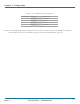
with the “>” prompt character. If you then type “help” and then press the ENTER KEY, the switch will respond with the rack
address, software version, and a list of the available commands—see Table 5-1.