LWE100A LWE100A-KIT LWE100AE LWE100AE-KIT LWE100A-W1 LWE100A-W2 LWE100A-KIT-W1 LWE100A-KIT-W2 Wireless P-T-P Ethernet Extender User Manual Extend Ethernet links between buildings wirelessly BLACK BOX and with ease. ® Provides affordable point-to-point wireless Ethernet extension up to 6.2 miles (10 km). Customer Support Information Order toll-free in the U.S.: Call 877-877-BBOX (outside U.S.
Trademarks Used in this Manual Trademarks Used in this Manual Black Box and the Double Diamond logo are registered trademarks of BB Technologies, Inc. Google Chrome is a registered trademark of Google Inc. Microsoft and Internet Explorer are registered trademarks of Microsoft Corporation. Firefox is a registered trademark of Mozilla Foundation. Netscape is a registered trademark of Netscape Communications Corporation.
FCC and IC RFI Statements FEDERAL COMMUNICATIONS COMMISSION and INDUSTRY CANADA RADIO FREQUENCY INTERFERENCE STATEMENTS Class B Digital Device. This equipment has been tested and found to comply with the limits for a Class B computing device pursuant to Part 15 of the FCC Rules. These limits are designed to provide reasonable protection against harmful interference in a residential installation. However, there is no guarantee that interference will not occur in a particular installation.
NOM Statement Instrucciones de Seguridad (Normas Oficiales Mexicanas Electrical Safety Statement) 1. Todas las instrucciones de seguridad y operación deberán ser leídas antes de que el aparato eléctrico sea operado. 2. Las instrucciones de seguridad y operación deberán ser guardadas para referencia futura. 3. Todas las advertencias en el aparato eléctrico y en sus instrucciones de operación deben ser respetadas. 4. Todas las instrucciones de operación y uso deben ser seguidas. 5.
Table of Contents Table of Contents 1. Specifications..........................................................................................................................................................................7 1.1 General...........................................................................................................................................................................7 1.2 Radio.............................................................................................
Table of Contents 6.8 Password......................................................................................................................................................................44 6.9 Certificate Settings.......................................................................................................................................................45 7. Monitoring Tools..................................................................................................................
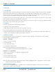
Chapter 1: Specifications 1. Specifications 1.1 General Standards — IEEE 802.3u MDI/MDI-X 10/100 Fast Ethernet, IEEE 80.11b/g wireless LAN interface, IEEE 802.1n draft wireless LAN standard Temperature Tolerance — Operating: -4 to +158° F (-20 to +70° C); Storage: -22 to +176° F (-30 to +80° C) Humidity Tolerance — Operating: 10–95%; Storage: 10–95% Power — Input current: 0.5 A maximum; Output Voltage: 15 V; Output Current: 0.8 A Size — 2.4"H x 2.5"W x 8.9"D (6.1 x 6.4 x 22.8 cm) Weight — < 1.1 lb. (< 0.
Chapter 2: Overview 2. Overview 2.1 Introduction Designed for outdoor environment applications, the Wireless P-T-P Ethernet Extender is a high-performance last-mile broadband solution that provides reliable wireless network coverage. As an IEEE 802.11b/g compliant wireless device, the Wireless P-T-P Ethernet Extender is able to provide stable and efficient wireless performance.
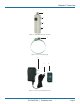
Chapter 2: Overview 1 2 2 2 Figure 2-1. LWE100A Ethernet extender. 3 Figure 2-2. Pole-mounting ring. 4 5 6 Figure 2-3. Power cord and PoE injector. 724-746-5500 | blackbox.
Chapter 2: Overview Table 2-1. Components. Number Component Description 1 (1) reverse N-type connector Ground the connector first, then install the antenna here. 2 (3) pole mounts You will install the pole mounting ring through these mounts. 3 (1) pole mounting ring Secures the extender to the pole 4 (1) U.S. power plug Connects to a power source 5 (1) 2.
Chapter 3: Hardware Installation 3. Hardware Installation This chapter describes safety precautions and product information you have to know and check before installing the Wireless P-T-P Ethernet Extender. 3.1 Preparing for Installation Read this chapter before installing the extender. It describes safety precautions and needed product information. 3.2 Professional Installation Required Use a professional installer who is well trained in the RF installation and knowledgeable about local regulations. 3.
Chapter 3: Hardware Installation Figure 3-1. Removing the bottom cover. 2. Plug a standard Ethernet cable into the RJ-45 port. See Figure 3-2. Figure 3-2. Plugging in the cable. 3. Slide the cover back to seal the bottom of the Wireless P-T-P Ethernet Extender. Page 12 724-746-5500 | blackbox.
Chapter 3: Hardware Installation Figure 3-3. Replacing the cover. 4. Take out the power cord and PoE injector, and plug the power cord into the DC port of the PoE injector as the right-side picture in Figure 3-4 shows. Figure 3-4. Installing the power cord and PoE injector. 5. Put what you assembled in step 3 and step 4 together by plugging the other side of the Ethernet cable from step 3 into the PoE port of the PoE injector shown in step 4.
Chapter 3: Hardware Installation Figure 3-5. Extender. 3.5.2 Pole Mounting 1. Turn the Wireless P-T-P Ethernet Extender over. Put the pole mounting ring through the middle hole of the Wireless P-T-P Ethernet Extender. NOTE: Use a screwdriver to unlock the pole-mounting ring before putting it through the Wireless P-T-P Ethernet Extender as the right-side picture in Figure 3-6 shows. Page 14 724-746-5500 | blackbox.
Chapter 3: Hardware Installation Figure 3-6. Unlocking the pole-mounting ring. 2. Mount the Wireless P-T-P Ethernet Extender firmly to the pole by locking the pole mounting ring tightly. Figure 3-7. Mounting the extender to a pole. 3. When installation is complete, the extender should look like Figure 3-8. 724-746-5500 | blackbox.
Chapter 3: Hardware Installation Figure 3-8. Extender installed outdoors on a pole. 3.5.3 Using the External Antenna If you prefer to use the external antenna with N-type connector for your application instead of the built-in directional antenna, follow the steps below. 1. Grab the black rubber on the top of the Wireless P-T-P Ethernet Extender, and slightly pull it up as shown in Figure 3-9. The metal N-type connector will appear. Page 16 724-746-5500 | blackbox.
Chapter 3: Hardware Installation Figure 3-9. Installing the external antenna. 2. Connect your antenna with the N-type connector on the top of the Wireless P-T-P Ethernet Extender. NOTES: 1. Before connecting the external antenna with the N-type connector to the Wireless P-T-P Ethernet Extender, users should prepare the cable in advance, if needed. 2. While connecting the N-type connectors, users should be careful not to damage the connectors.
Chapter 3: Hardware Installation 3. Connect the other end of the grounding wire to the earth ground. Figure 3-11. Connecting the other end of the grounding wire. Page 18 724-746-5500 | blackbox.
Chapter 4: Basic Settings 4. Basic Settings 4.1 Factory Default Settings To return the extender to its factory-default settings, see Section 6.6. Table 4-1. Wireless P-T-P Ethernet Extender Factory Default Settings. Parameter Default Setting Username admin Password password Wireless Device Name apXXXXXX (X represents the last 6 digits of the Ethernet MAC address) Operating Mode AP Data Rate Auto LAN IP Address 192.168.1.1 LAN Subnet Mask 255.255.255.0 LAN Gateway 0.0.0.
Chapter 4: Basic Settings 4.2 System Requirements Before configuration, make sure your system meets the following requirements: • You will need a computer coupled with a 10/100 BASE-TX adapter; • Configure the computer with a static IP address of 192.168.1.x. NOTE: The default IP address of Wireless P-T-P Ethernet Extender is 192.168.1.1. (X cannot be 0, 1, nor 255); • A Web browser on a PC for configuration such as Microsoft® Internet Explorer® 6.0 or above, Netscape®, Firefox®, or Google Chrome®. 4.
Chapter 4: Basic Settings Figure 4-2. Main page. NOTE: The username and password are case-sensitive, and the password should be no more than 19 characters. 4.4 Basic System Settings If you are using the Wireless P-T-P Ethernet Extender for the first time, we recommend starting configuration from “Basic Settings” in the “System” screen shown next. Figure 4-3. Basic system settings. 724-746-5500 | blackbox.
Chapter 4: Basic Settings Basic Settings • Device Name: Specify the device name, which is composed of no more than 15 characters with (0-9), (A-Z), (a-z), or (-). • Network Mode: Specify the network mode, including Bridge and Router. It is easy to configure parameters in Bridge Mode; however, users must pay extra attention to the way they configure the device when it is set to Router Mode. For details, please refer to “TCP/IP Settings” below.
Chapter 4: Basic Settings NOTES: 1. When the IP address of the extender is changed, the clients on the network often need to wait for a while or even reboot before they can access the new IP address. For immediate access to the bridge, flush the netbios cache on the client computer by running the “nbtstat –r” command before using the device name of the CPE to access its Web management page. 2. If the IEEE 802.
Chapter 4: Basic Settings WARNING: Bridge mode and AP Repeater mode are similar to AP mode when the device is set to Router mode; the WAN is on wired port and the LAN is on wireless port. Users must also connect the extender with another wireless device before it is set to Router mode and access the extender via the connected wireless device. 4.5 Time Settings Compliant with NTP, the Wireless P-T-P Ethernet Extender keeps time to match the Internet time.
Chapter 4: Basic Settings Figure 4-7. RADIUS settings. Authenticating RADIUS Server This is for RADIUS authentication. It can communicate with RADIUS through IP Address, Port, and Shared Secret.
Chapter 4: Basic Settings Figure 4-8. Source IP filtering. Destination IP Filtering: Destination IP filtering gives you the ability to restrict the computers in a LAN from accessing certain Websites in a WAN according to specified IP addresses. Check the “Enable Source IP Filtering” checkbox and enter the IP address of the clients you want to restrict. Click on the “Apply” button to make the setting take effect. Figure 4-9. Destination IP filtering. Page 26 724-746-5500 | blackbox.
Chapter 4: Basic Settings Source Port Filtering: Source port filtering enables you to restrict certain ports of data packets from your local network to the Internet through the Wireless P-T-P Ethernet Extender. Use these filters to help secure or restrict your local network. Figure 4-10. Source port filtering. Destination Port Filtering: The destination port filtering enables you to restrict certain ports of data packets from your local network to the Internet through the Wireless P-T-P Ethernet Extender.
Chapter 4: Basic Settings Port Forwarding: The port forwarding allows you to automatically redirect common network services to a specific machine behind the NAT firewall. These settings are only necessary if you want to host a Web server or mail server on the private local network behind Wireless P-T-P Ethernet Extender’s NAT firewall. Figure 4-12. Port forwarding. DMZ: A Demilitarized Zone is used to provide Internet services without sacrificing unauthorized access to its local private network.
Chapter 4: Basic Settings 4.8 Basic Wireless Settings Open “Basic Settings” in “Wireless” to configure basic wireless. Figure 4-14. Basic wireless settings. Disable Wireless LAN Interface Check this option to disable the WLAN interface. The wireless module of the Wireless P-T-P Ethernet Extender will then stop working and no wireless device can connect to it. Wireless Mode Four operating modes are available in the Wireless P-T-P Ethernet Extender.
Chapter 4: Basic Settings 802.11 Mode The Wireless P-T-P Ethernet Extender can communicate with wireless devices that conform to 802.11b/g or 802.11b/g/n. HT Protect Enable HT (High Throughput) protect to ensure HT transmission with MAC mechanism. Under 802.11n mode, the wireless client can be divided into HT STA and Non-HT STA. The one with HT protect enabled gets higher throughput. Frequency/Channel Channel varies because the available band differs from country to country.
Chapter 4: Basic Settings 4.9 Site Survey Under wireless client mode, the Wireless P-T-P Ethernet Extender is able to perform a site survey. It detects available information about the access points. Open “Basic Settings” in “Wireless,” by clicking the “Site Survey” button beside the “Wireless Mode” option. The wireless site survey window will pop up with a list of available APs in the vicinity. Select the AP you want to connect to and click “Selected” to establish connection. Figure 4-15. Site Survey. 4.
Chapter 4: Basic Settings Figure 4-16. VAP Profile settings. Figure 4-17. VAP Profile1 settings. Basic Settings Profile Name: Name of the VAP profile. Wireless Network Name: Enter the virtual SSID for the VAP. Broadcast SSID: In AP mode, you need to hide the network name when you are in a wireless environment that may have potential risk. By disabling broadcast SSID, the STA cannot scan and find the Wireless P-T-P Ethernet Extender, so malicious attack by an illegal STA can be avoided.
Chapter 4: Basic Settings Wireless Separation: Wireless separation enhances the security of network transmission. Under the mode (except wireless client mode), enable “Wireless Separation” to prevent the communication among associated wireless clients. WMM Support: WMM (Wi-Fi Multimedia) is a subset of 802.11e.
Chapter 5: Advanced Settings 5. Advanced Settings 5.1 Advanced Wireless Settings Open “Advanced Settings” in “Wireless” to make advanced wireless settings. Figure 5-1. Advanced wireless settings. A-MPDU/A-MSDU Aggregation The data rate of your AP (except wireless client mode) could be enhanced greatly with this option enabled; however, if your wireless clients don’t support A-MPDU/A-MSDU aggregation, we do not recommended that you enable it. Short GI Under 802.
Chapter 5: Advanced Settings Preamble Type It defines some details on the 802.11 physical layer. “Long” and “Auto” are available. IGMP Snooping Available in AP/Router mode, IGMP snooping is the process of listening to IGMP network traffic. When IGMP snooping is enabled, the AP will listen to IGMP membership reports, queries, and leave messages to identify the ports that are members of multicast groups.
Chapter 5: Advanced Settings Figure 5-2. Security settings. Network Authentication Open System: This enables any device to join the network without performing a security check. Shared Key: Data encryption and key are required for wireless authentication (not available in Bridge/AP Repeater mode). Legacy 802.1x: Available in AP/Wireless Client mode, this provides the rights to access the wireless network and wired Ethernet.
Chapter 5: Advanced Settings Data Encryption If data encryption is enabled, the key is required and only other devices using the the same key can communicate with each other. None: Available only when the authentication type is open system. 64 bits WEP: Consists of 10 hexadecimal numbers. 128 bits WEP: Consists of 26 hexadecimal numbers. 152 bits WEP: Consists of 32 hexadecimal numbers. TKIP: Temporal Key Integrity Protocol, which is a kind of dynamic encryption, is co-used with WPA-PSK, etc.
Chapter 5: Advanced Settings MAC Address Enter the MAC address of the wireless client that you want to list into the access control list, click “Apply,” and it will be added into the table at the bottom. Delete Selected/All Check the box before one or more MAC addresses of wireless client(s) that you want to cancel, and click “Delete Selected” or “Delete All” to cancel that access control rule. 5.2.
Chapter 6: Management 6. Management 6.1 Remote Management The Wireless P-T-P Ethernet Extender provides remote management, including Telnet, SNMP, FTP, SSH, HTTPS, and exclusive WISE tool, making configuration more convenient and secure. With “Normal” selected, Telnet, SNMP, and FTP are activated as default remote management options. To use secure management tools such as SSH, HTTPS and WISE, select “Secure.” You can also choose “Customized” to enable any methods as desired. Figure 6-1. Remote settings.
Chapter 6: Management Protocol Version Select the SNMP version, and keep it identical on the Wireless P-T-P Ethernet Extender and the SNMP manager. The Wireless P-T-P Ethernet Extender supports SNMP v2/v3. Server Port Change the server port for a service if needed; however, you must use the same port to use that service for remote management. Get Community Specify the password for the incoming Get and GetNext requests from the management station. By default, it is set to “public” and allows all requests.
Chapter 6: Management Password: Specify a password for the SNMPv3 administrator or user. Only the SNMP commands carrying this password are allowed to access the Wireless P-T-P Ethernet Extender. Confirm Password: Input that password again to make sure it is your desired one. Access Type: Select “Read Only” or “Read and Write.” Authentication Protocol: Select an authentication algorithm. SHA authentication is stronger than MD5, but is slower.
Chapter 6: Management Radius Administrative-User Radius Admin Username: Enter the username of the Radius Administrator. Radius Admin Password: Enter the password of the Radius Administrator. Captive Portal UAM Portal URL: Enter the address of the UAM portal server. UAM Secret: Enter the secret password between the redirect URL and the Hotspot. 6.
Chapter 6: Management Figure 6-6. Backup/retrieve settings. Save Setting to File: When you click “Save,” a dialog box will pop up. Save it, then the configuration file ap.cfg will be generated and saved to your local computer. Load Settings from File: By clicking “Browse,” a file selection menu will appear; select the file you want to load, like ap.cfg. Click “Upload” to load the file. After automatically rebooting, new settings are applied. 6.
Chapter 6: Management Restore factory default settings via the “Reset” button: If software in the Wireless P-T-P Ethernet Extender unexpectedly crashes and you can no longer reset the unit via Web, you may do hardware reset via the reset button. Press and hold the button for at least five seconds and then release it until the PWR LED blinks. 6.7 Reboot You can reboot your Wireless P-T-P Ethernet Extender from “Configuration File” in “Management.
Chapter 6: Management 6.9 Certificate Settings In Client mode, when EAP-TLS is used, the RADIUS server must know which user certificates to trust. The server can trust all certificates issued by a given CA. To import a user certificate, from Import User Certificates, click “Browse” and specify the location where the user certificate is placed. Click “Import.” Figure 6-10. Certificate settings. 724-746-5500 | blackbox.
Chapter 7: Monitoring Tools 7. Monitoring Tools 7.1 System Log System log records events that occur on the Wireless P-T-P Ethernet Extender, including station connection, disconnection, system reboot, etc. Open “System Log” in “Tools.” Figure 7-1. System log. Remote Syslog Server Enable Remote Syslog: Enable System log to alert remote server. IP Address: Specify the IP address of the remote server. Port: Specify the port number of the remote server. 7.
Chapter 7: Monitoring Tools Figure 7-2. Site survey. 7.3 Ping Watchdog If the extender unexpectedly disconnects and cuts off your ability the log in to the unit, use the ping watchdog to reboot. Figure 7-3. Ping watchdog. Ping Watchdog Enable Ping Watchdog: To activate ping watchdog, check this checkbox. IP Address to Ping: Specify the IP address of the remote unit to ping. Ping Interval: Specify the interval time to ping the remote unit.
Chapter 7: Monitoring Tools 7.4 Data Rate Test The Data Rate Test enables you to test the current RSSI at each data rate between your Wireless P-T-P Ethernet Extenders. Figure 7-4. Data rate test. 7.5 Antenna Alignment In Bridge mode, when the bridges are not easily visible from the location where the dish will be installed, the antenna alignment tool can help you evaluate the position of the unit and adjust the angle of the antenna more precisely.
Chapter 7: Monitoring Tools Figure 7-5. Antenna alignment. 7.6 Speed Test The speed test monitors the current data transmission (TX) and data reception (RX) rate with the remote Wireless P-T-P Ethernet Extender. Enter the IP address of the remote extender, type in the user name/password and click “Test.” The result will display in the bottom STATUS. You may test single TX/RX or bi-directional. Figure 7-6. Speed test. 724-746-5500 | blackbox.
Chapter 8: Status 8. Status 8.1 View Basic Information Open “Information” in “Status” to check the basic information of the CPE, which is read-only. Information includes system information, LAN settings, wireless setting, and interface status. Click “Refresh” at the bottom to get the real-time information. Figure 8-1. Basic information. 8.
Chapter 8: Status By clicking on the MAC address of the selected device on the Web, you may see more details including device name, connection time, signal strength, noise floor, ACK timeout, link quality, IP information, current data rate, and current TX/RX packets. Figure 8-3. Association node details. 8.3 View Network Flow Statistics Open “Statistics” in “Status” to check the data packets received on and transmitted from the wireless and Ethernet ports. Click “Refresh” to view current statistics.
Chapter 8: Status Poll Interval: Specify the refresh time interval in the box beside “Poll Interval” and click “Set Interval” to save the settings. “Stop” discontinues the auto refresh of network flow statistics. 8.4 View ARP Table Open “ARP Table” in “Status” as shown below. Click “Refresh” to view current table. Figure 8-5. ARP table. 8.5 View Bridge Table Open “Bridge Table” in “Status” as below. Click “Refresh” to view current connected status. Figure 8-6. Bridge table. 8.
Chapter 8: Status Figure 8-7. DHCP client table. 8.7 View Network Activities The network activities enables you to monitor the current Wireless and Ethernet TX/RX data traffic in graphical and numerical form on the Skyport Web. The chart scale and throughput dimension (bps, kbps, Mbps) changes dynamically according to the mean throughput value. You can manually update throughput statistics using the “Refresh” button. Figure 8-8. Network activities. 724-746-5500 | blackbox.
Chapter 9: Troubleshooting 9. Troubleshooting This chapter provides troubleshooting procedures for basic problems with the Wireless P-T-P Ethernet Extender. 9.1 Frequently Asked Questions Q 1. What is the MAC address of the Wireless P-T-P Ethernet Extender? MAC Address distinguishes itself by a unique identity among network devices. It appears in two places: 1. Each device has a label posted with the MAC address. Please see below. Figure 9-1. MAC address. 2.
Chapter 9: Troubleshooting 9.2 Contacting Black Box If you determine that your Wireless P-T-P Ethernet Extender is malfunctioning, do not attempt to alter or repair the unit. It contains no user-serviceable parts. Contact Black Box Technical Support at 724-746-5500 or info@blackbox.com. Before you do, make a record of the history of the problem. We will be able to provide more efficient and accurate assistance if you have a complete description, including: • the nature and duration of the problem.
Appendix A: ASCII Appendix A. ASCII WEP can be configured with a 64-bit, 128-bit or 152-bit Shared Key (hexadecimal number or ACSII). As defined, the hexadecimal number is represented by 0-9, A-F or a-f; ACSII is represented by 0-9, A-F, a-f or punctuation. Each one consists of a two-digit hexadecimal. Table A-1. ASCII.
Appendix B. SSH Settings Appendix B. SSH Settings Table B-1. CLI commands.
Appendix B. SSH Settings Table B-1 (Continued). CLI commands.
Appendix B. SSH Settings Table B-1 (Continued). CLI commands.
Appendix B. SSH Settings Table B-1 (Continued). CLI commands.
Appendix B. SSH Settings Table B-1 (Continued). CLI commands.
Appendix B. SSH Settings Table B-1 (Continued). CLI commands.
Appendix B. SSH Settings Table B-1 (Continued). CLI commands.
Appendix B. SSH Settings Table B-1 (Continued). CLI commands.
Appendix B. SSH Settings Table B-1 (Continued). CLI commands.
NOTES Page 66 724-746-5500 | blackbox.
NOTES 724-746-5500 | blackbox.
Black Box Tech Support: FREE! Live. 24/7. Tech support the way it should be. Great tech support is just 30 seconds away at 724-746-5500 or blackbox.com. About Black Box Black Box provides an extensive range of networking and infrastructure products. You’ll find everything from cabinets and racks and power and surge protection products to media converters and Ethernet switches all supported by free, live 24/7 Tech Support available in 30 seconds or less. © Copyright 2012. Black Box Corporation.