MARCH 2006 SW555A SW555AE SW556A-R2 SW556AE Remote Management Switch CUSTOMER SUPPORT INFORMATION Order toll-free in the U.S.: Call 877-877-BBOX (outside U.S. call 724-746-5500) FREE technical support 24 hours a day, 7 days a week: Call 724-746-5500 or fax 724-746-0746 Mailing address: Black Box Corporation, 1000 Park Drive, Lawrence, PA 15055-1018 Web site: www.blackbox.com • E-mail: info@blackbox.
FCC AND IC RFI STATEMENTS FEDERAL COMMUNICATIONS COMMISSION AND INDUSTRY CANADA RADIO FREQUENCY INTERFERENCE STATEMENTS This equipment generates, uses, and can radiate radio frequency energy and if not installed and used properly, that is, in strict accordance with the manufacturer’s instructions, may cause interference to radio communication.
REMOTE MANAGEMENT SWITCH NORMAS OFICIALES MEXICANAS (NOM) ELECTRICAL SAFETY STATEMENT INSTRUCCIONES DE SEGURIDAD 1. Todas las instrucciones de seguridad y operación deberán ser leídas antes de que el aparato eléctrico sea operado. 2. Las instrucciones de seguridad y operación deberán ser guardadas para referencia futura. 3. Todas las advertencias en el aparato eléctrico y en sus instrucciones de operación deben ser respetadas. 4. Todas las instrucciones de operación y uso deben ser seguidas. 5.
NOM STATEMENT 12. Precaución debe ser tomada de tal manera que la tierra fisica y la polarización del equipo no sea eliminada. 13. Los cables de la fuente de poder deben ser guiados de tal manera que no sean pisados ni pellizcados por objetos colocados sobre o contra ellos, poniendo particular atención a los contactos y receptáculos donde salen del aparato. 14. El equipo eléctrico debe ser limpiado únicamente de acuerdo a las recomendaciones del fabricante. 15.
REMOTE MANAGEMENT SWITCH TRADEMARKS USED IN THIS MANUAL BLACK BOX and the Double Diamond logo are registered trademarks of BB Technologies, Inc. IBM is a registered trademark of International Business Machines Corporation. Any other trademarks mentioned in this manual are acknowledged to be the property of the trademark owners.
CONTENTS Contents Chapter Page 1. Specifications . . . . . . . . . . . . . . . . . . . . . . . . . . . . . . . . . . . . . . . . . . . . . . . . . . . . 6 2. Overview . . . . . . . . . . . . . . . . . . . . . . . . . . . . . . . . . . . . . . . . . . . . . . . . . . . . . . . . 7 2.1 Port Selector. . . . . . . . . . . . . . . . . . . . . . . . . . . . . . . . . . . . . . . . . . . . . . . . . . 7 2.2 Power Controller . . . . . . . . . . . . . . . . . . . . . . . . . . . . . . . . . . . . . . . . . . . .
REMOTE MANAGEMENT SWITCH 1. Specifications Speed: 300 bps to 115.2 kbps Character Format: 8 data bits, no parity, and 1 stop bit; or 7 data bits, even or odd parity, and 1 stop bit Interface: RS-232 asynchronous Connectors: (4) DB25 subminiature female for ports A through D; (1) DB25 subminiature male for master port (pins supported: 1–8, 20) Power: SW555A, SW556A-R2: Input: 120 VAC, 60 Hz, via a standard NEMA 5-15 plug on a 6-ft. (1.
CHAPTER 2: Overview 2. Overview The Remote Management Switch (part number SW555A or SW555AE) can be used for serial switching and as an AC power control system. A Remote Management Switch with Modem (part number SW556A-R2 or SW556AE— includes 56 kbps modem) is also available. See Figure 2-1. MANUAL Figure 2-1. The switch’s front and rear views. 2.
REMOTE MANAGEMENT SWITCH 3. Installation 3.1 Master and Switched Ports Connect the Remote Management Switch’s back-panel ports A through D to your RS-232 devices. Each port uses a DB25 subminiature connector and supports the leads shown in Table 3-1 for asynchronous communications. Table 3-1. DB25 connector supported leads.
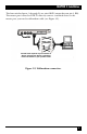
CHAPTER 3: Installation The four switched ports, A through D, are wired DCE (output data on pin 3, RD). The master port is wired as DTE. To directly connect a terminal device to the master port, you need a null-modem cable (see Figure 3-2). Control leads required vary from device to device. Consult your device’s operations manual for details on your specific needs. Figure 3-2. Null-modem connection.
REMOTE MANAGEMENT SWITCH 3.2 RTS/DTR Selection WARNING To avoid electrical shock, you MUST remove power to the Remote Management Switch BEFORE opening the top cover. D C B A Master DTR RTS Jumpers JP1 through JP4 let you select RTS (default) or DTR as the control lead used for lead control. To access these jumpers, disconnect the power source and remove the Remote Management Switch’s top cover. The jumpers are located behind the B and D port connectors (see Figure 3-3).
CHAPTER 3: Installation 3.3 Internal Modem Option (SW556A-R2, SW556AE) An internal modem is included in two models of the Remote Management Switch. Part numbers SW556A-R2 and SW556AE incorporate a 56-kbps modem. Connect the modem to the dial line via an RS-232 to modular adapter (included). This adapter connects to the master port and to an RJ-11 modular jack. (See Figure 3-4.) The modem complies with FCC Class A and uses the standard AT command set.
REMOTE MANAGEMENT SWITCH 4. Operation 4.1 Four Modes of Operation You can operate the Remote Management Switch in four possible ways: menu selection, escape code sequences, lead control, and manual control. 4.1.1 MENU SELECTION By connecting to the master port, you can switch to any of the four ports (A through D) or operate any of the four relays. The menu system allows convenient naming of each port and relay, as well as allowing setup of all Remote Management Switch parameters.
CHAPTER 4: Operation The Remote Management Switch automatically detects the rate of operation, allowing connection at 300 bps to 115.2 kbps. Using the default speed will allow the fastest access to the unit. To invoke the auto rate detector, press the Enter key one or more times as needed. When the Switch detects the rate, it will respond with the security login prompt: Login > Enter the default security code (the default code is “TEST,” all caps, case-sensitive).
REMOTE MANAGEMENT SWITCH Once you select a port, the switch will clear the screen and generate the following message: x Selected (x=the programmed name of the port) Enter ESC{PASSWORD}ESC to return to menu At this point, the master port is connected through to the port selected. The Remote Management Switch is passive to the messages sent between the master port and the port selected.
CHAPTER 4: Operation 1) Den 2) Eng 3) Den 4) Eng Outlet Outlet Outlet Outlet 1=>cycling 2 3 4 # - Select relay to toggle P# - Pulse relay X - Exit Enter > Figure 4-4. Cycling. 4.2.3 PROGRAMMING 1) Device labels 2) Password 3) Baud: 19200 4) Parity/Data: N,8 5) Lead: N 6) Resp: Y 7) Mode: Modem 8) Cycle time: 5 9) Time out: 0 X) Exit Enter >1 Figure 4-5. Programming menu. 1) Device Labels. This lets you change the screen labels for the ports and powercontrol outlets. See Figure 4-6.
REMOTE MANAGEMENT SWITCH Enter the label you want to change. The current label is displayed, along with a prompt for the new name. Type in a new label and then confirm the selection. Labels can be up to 24 characters. See Figure 4-7. CURRENT LABEL PORT A PORT A NEW LABEL PORT A> Your New Name PORT LABEL CHANGED FROM PORT A TO Your New Name SAVE CHANGES? (Y/N) > Figure 4-7. Entering new label name. 2) Password. The password is used for logging into the menu system and in every escape sequence.
CHAPTER 4: Operation 5) Lead Control. This selection determines whether control leads from the switched ports can be used to access the master port. The factory default is lead control disabled. Select Yes or No. 6) Command Response. The switch can send a response to escape sequences to let the operator know that the switch has taken place. The factory default is responses disabled. Select Yes or No to change the setting. 7) Modem or Terminal Mode. Sets the switch for either terminal or modem use.
REMOTE MANAGEMENT SWITCH 4.3 Escape Code Control The Remote Management Switch allows direct computer control using simple ASCII strings. These codes can control the port selection and relay operation. To access the switch for code control, enter the commands as shown below. To invoke the auto-rate detector, press the Escape key one or more times, until the switch responds with BLACK BOX READY.
CHAPTER 4: Operation Responses to Code Control commands are optional and set via the Programming menu. 4.4 Lead Control of Ports The Remote Management Switch can automatically select ports via control leads. You must set up this feature before using the switch. Any port can access the master by raising the RTS or DTR lead (jumper selectable) provided no other port is already connected by Menu, Manual, or Code Control. If another port is connected, the request is placed in queue.
© Copyright 2006. Black Box Corporation. All rights reserved.