JULY 2002 IC1020A IC1021A IC1022A Dual-Port USB Hub—RS-232/422/485 Quad-Port USB Hub—RS-422/485 Quad-Port USB Hub—RS-232/422/485 CUSTOMER SUPPORT INFORMATION Order toll-free in the U.S.: Call 877-877-BBOX (outside U.S. call 724-746-5500) FREE technical support 24 hours a day, 7 days a week: Call 724-746-5500 or fax 724-746-0746 Mailing address: Black Box Corporation, 1000 Park Drive, Lawrence, PA 15055-1018 Web site: www.blackbox.com • E-mail: info@blackbox.
FCC AND IC RFI STATEMENTS FEDERAL COMMUNICATIONS COMMISSION and INDUSTRY CANADA RADIO FREQUENCY INTERFERENCE STATEMENTS Class B Digital Device. This equipment has been tested and found to comply with the limits for a Class B computing device pursuant to Part 15 of the FCC Rules. These limits are designed to provide reasonable protection against harmful interference in a residential installation. However, there is no guarantee that interference will not occur in a particular installation.
DUAL- AND QUAD-PORT USB HUBS EMC Directive Statement Products bearing the CE Label fulfill the requirements of the EMC directive (89/336/EEC) and of the low-voltage directive (73/23/EEC) issued by the European Commission. To obey these directives, the following European standards must be met: • EN55022 Class B—Limits and methods of measurement of radio interference characteristics of information technology equipment.
NOM STATEMENT NORMAS OFICIALES MEXICANAS (NOM) ELECTRICAL SAFETY STATEMENT INSTRUCCIONES DE SEGURIDAD 1. Todas las instrucciones de seguridad y operación deberán ser leídas antes de que el aparato eléctrico sea operado. 2. Las instrucciones de seguridad y operación deberán ser guardadas para referencia futura. 3. Todas las advertencias en el aparato eléctrico y en sus instrucciones de operación deben ser respetadas. 4. Todas las instrucciones de operación y uso deben ser seguidas. 5.
DUAL- AND QUAD-PORT USB HUBS 12. Precaución debe ser tomada de tal manera que la tierra fisica y la polarización del equipo no sea eliminada. 13. Los cables de la fuente de poder deben ser guiados de tal manera que no sean pisados ni pellizcados por objetos colocados sobre o contra ellos, poniendo particular atención a los contactos y receptáculos donde salen del aparato. 14. El equipo eléctrico debe ser limpiado únicamente de acuerdo a las recomendaciones del fabricante. 15.
TRADEMARKS TRADEMARKS USED IN THIS MANUAL AT, IBM, and PS/2 are registered trademarks of International Business Machines Corporation. Windows is a registered trademark of Microsoft Corporation. Any other trademarks mentioned in this manual are acknowledged to be the property of the trademark owners.
DUAL- AND QUAD-PORT USB HUBS Contents Chapter Page 1. Specifications . . . . . . . . . . . . . . . . . . . . . . . . . . . . . . . . . . . . . . . . . . . . . . . . . . 7 2. Introduction . . . . . . . . . . . . . . . . . . . . . . . . . . . . . . . . . . . . . . . . . . . . . . . . . . . 8 2.1 Overview . . . . . . . . . . . . . . . . . . . . . . . . . . . . . . . . . . . . . . . . . . . . . . . . . . 8 2.2 What’s Included . . . . . . . . . . . . . . . . . . . . . . . . . . . . . . . . . . . . . . . .
CHAPTER 1: Specifications 1. Specifications Standards: USB version 1.1 Speed: RS-232: Up to 460.8 kbps; RS-422/485: Up to 921.
DUAL- AND QUAD-PORT USB HUBS 2. Introduction 2.1 Overview The USB Hub equips the PC with 2 or 4 USB to RS-232/422/485 or RS-422/485 asynchronous serial ports. It gives you a versatile interface for common serial needs. Three models are available: • The Dual-Port USB Hub (IC1020A) has 2 USB ports to RS-232/422/485 serial ports. • The Quad-Port USB Hub (IC1021A) has 4 USB ports to RS-422/485 serial ports. • The Quad-Port USB Hub (IC1022A) has 4 USB ports to RS-232/422/485 serial ports.
CHAPTER 2: Introduction 2.4 Connector Pin Assignments The IC1020A has one USB Type B connector and two DB9 male connectors. The IC1021A and IC1022A have one USB Type B connector and four DB9 male connectors. The pinouts for the DB9 connectors are described in Tables 2-1 and 2-2. Table 2-1. RS-422/485 DB9 male connector pin assignments.
DUAL- AND QUAD-PORT USB HUBS 3. Installation 3.1 Operating System Installation Choose Install Software at the beginning of the CD and follow the prompts to install SeaCOM. 3.2 System Installation The screen capture shown in Figure 3-1 is taken from a Windows® 98 installation. Your particular operating system may differ slightly from what is shown, based on your version of Windows. The USB Hub can be connected to any upstream type A port either at the PC host or an upstream hub.
CHAPTER 3: Installation Figure 3-1. System Properties screen, Device Manager tab. You can access your new COM ports by using the assigned COM identifiers as shown in Figure 3-1. In this case, it is COM3, 4, 5, and 6. However, this assignment will vary from system to system. At this point, the hardware is recognized and ready to use.
DUAL- AND QUAD-PORT USB HUBS 4. Configuration 4.1 Original Configuration This device ships with the following configuration: • 422 mode, • 120 ohm termination, • 1 K-ohm pull-up resistance on RX+, and • 1 K-ohm pull-down resistance on RX-. To change this configuration, you must open the box. Do this by removing the four screws located on the bottom. When reassembling, please note that the top and bottom are keyed to fit in only one direction. 4.
CHAPTER 4: Configuration Table 4-1. Jumper settings. Jumper Port RS-232 E5 E6 E7 E8 2 2 1 1 X RS-422/485 X X X Switch SW4 Settings To configure the ports on the Dual-Port USB Hub for RS-422/RS-485 instead of RS-232, select Jumper E7 for Port 1 and Jumper E6 for Port 2. (See Table 4-1.) When you are running RS-422 or RS-485, you also need to set switch SW4, positions 1 through 10 (see Figure 4-1 and Table 4-2). For example, to set RS-485 2-wire operation on Port 1, set SW4-1 and 4-2 to ON.
DUAL- AND QUAD-PORT USB HUBS Table 4-2. DIP-switch SW4 settings. Switch Setting Switch Number Port Description RS-485 RS-422 L L T PD PU L L T PD PU SW4-1 SW4-2 SW4-3 SW4-4 SW4-5 SW4-6 SW4-7 SW4-8 SW4-9 SW4-10 1 1 1 1 1 2 2 2 2 2 TX+ to RX+ TX- to RXTermination 1K Pull-Down 1K Pull-Up TX+ to RX+ TX- to RXTermination 1K Pull-Down 1K Pull-Up ON ON ON ON ON ON ON ON ON ON OFF OFF ON OFF OFF OFF OFF ON OFF OFF L = Loops TX+ to RX+ or RX- to TX- for two-wire operation.
CHAPTER 4: Configuration Table 4-3. DIP-switch SW3 settings. Switch Setting Switch Port Number Description RS-485 RS-422 485 NE 485 NE SW3-1 SW3-2 SW3-3 SW3-4 485 Mode (4-wire) 485 Mode, No Echo (2-wire) 485 Mode (4-wire) 485 Mode, No Echo (2-wire) ON ON ON ON OFF OFF OFF OFF 1 1 2 2 NE = No Echo. In a two-wire setup, the receiver will not echo back the transmitted data. 4.2.
DUAL- AND QUAD-PORT USB HUBS Table 4-4. DIP-switches SW2 and SW4 settings.
CHAPTER 4: Configuration Figure 4-4. RS-422/485 interface configuration. NOTE Switch positions SW3-1 and 2 are for Port 1, SW3-3 and 4 are for Port 2, SW1-1 and 2 are for Port 3, and SW1-3 and 4 are for Port 4. Table 4-5. DIP-switch SW1 and SW3 settings.
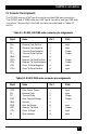
DUAL- AND QUAD-PORT USB HUBS each port. When selecting a configuration for your Hub, refer to Tables 4-6 through 4-8 and Figures 4-5 and 4-6. Jumpers E1, E2, E3, E4, E5, E6, E7, and E8 To configure Port 1 on the Quad-Port USB Hub for RS-232, select Jumper E8 on the circuit board. To configure Port 2 for RS-232, select Jumper E5. To configure Port 3 for RS-232, select Jumper E4, and for Port 4, select Jumper E1. (See Table 4-6 for all the jumper settings.) Table 4-6. Jumper settings.
CHAPTER 4: Configuration Figure 4-5. Switches SW2 and SW4. NOTE Switch positions SW4-1, 2, 3, 4, and 5 are for Port 1. Switch positions SW4-6, 7, 8, 9, and 10 are for Port 2. Switch positions SW2-1, 2, 3, 4, and 5 are for Port 3. Switch positions SW2-6, 7, 8, 9, and 10 are for Port 4. Table 4-7. DIP-switches SW2 and SW4 settings.
DUAL- AND QUAD-PORT USB HUBS Table 4-7 (continued). DIP-switches SW2 and SW4 settings. Switch Setting Switch Number Port Description RS-485 RS-422 PD PU SW4-9 SW4-10 2 2 1K Pull-Down 1K Pull-Up ON ON OFF OFF L = Loops TX+ to RX+ for two-wire operation. T = Adds a 120-ohm termination resistor between RX+ and RX-. PU = Pull-up. Adds a 1 K-ohm pull-up resistor to RX+. PD = Pull-down. Adds a 1 K-ohm pull-down resistor to RX-.
CHAPTER 4: Configuration Table 4-8. DIP-switch SW1 and SW3 settings. Switch Setting Switch Port Number Description RS-485 RS-422 485 NE 485 NE 485 NE 485 NE SW1-1 SW1-2 SW1-3 SW1-4 SW3-1 SW3-2 SW3-3 SW3-4 485 Mode (4-wire) 485 Mode, No Echo (2-wire) 485 Mode (4-wire) 485 Mode, No Echo (2-wire) 485 Mode (4-wire) 485 Mode, No Echo (2-wire) 485 Mode (4-wire) 485 Mode, No Echo (2-wire) ON ON ON ON ON ON ON ON OFF OFF OFF OFF OFF OFF OFF OFF 3 3 4 4 1 1 2 2 NE = No Echo.
DUAL- AND QUAD-PORT USB HUBS Appendix A. Troubleshooting A.1 Troubleshooting Tips Serial Utility test software is supplied on the included CD-ROM and will be used in the troubleshooting procedures. By using this software and following these simple steps, you can eliminate most common problems without calling Technical Support. 1. If your Hub isn’t working, first check to make sure that USB support is enabled in the System BIOS and that it’s functioning properly in the operating system.
APPENDIX A: Troubleshooting A.2 Calling Black Box If you determine that your USB Hub is malfunctioning, do not attempt to alter or repair the unit. It contains no user-serviceable parts. Contact Black Box at 724-746-5500. Before you do, make a record of the history of the problem. We will be able to provide more efficient and accurate assistance if you have a complete description, including: • the nature and duration of the problem. • when the problem occurs. • the components involved in the problem.
DUAL- AND QUAD-PORT USB HUBS Appendix B. Electrical Interfaces B.1 RS-232 Quite possibly the most widely used communication standard is RS-232. This implementation has been defined and revised several times and is often referred to as EIA/TIA-232. The IBM® PC AT® computer defined the RS-232 port on a DB9 connector, and subsequently the EIA/TIA approved this implementation as the EIA/TIA-574 standard.
APPENDIX B: Electrical Interfaces B.3 RS-485 RS-485 is backward-compatible with RS-422; however, it is optimized for partyline or multidrop applications. The output of the RS-422/485 driver is capable of being Active (enabled) or Tristate (disabled). This capability allows multiple ports to be connected in a multidrop bus and selectively polled. RS-485 allows cable lengths up to 4000 feet (1219.2 m) and data rates up to 10 Mbps. The signal levels for RS-485 are the same as those defined by RS-422.
DUAL- AND QUAD-PORT USB HUBS Appendix C: Asynchronous Communication In serial data communication, individual bits of a character are transmitted consecutively to a receiver that assembles the bits back into a character. Data rate, error checking, handshaking, and character framing (start/stop bits) are predefined and must correspond at both the transmitting and receiving ends. Asynchronous communication is the standard means of serial data communication for PC compatibles and PS/2® computers.
APPENDIX C: Asynchronous Communication Because each bit in asynchronous communication is sent consecutively, it is easy to generalize asynchronous communication by stating that each character is wrapped (framed) by pre-defined bits to mark the beginning and end of the serial transmission of the character. The data rate and communication parameters for asynchronous communication have to be the same at both the transmitting and receiving ends.
© Copyright 2002. Black Box Corporation. All rights reserved.