JUNE 2001 SW614A SW616A SW617A SW619A Customer Support Information: FREE tech support 24 hours a day, 7 days a week: Call 724-746-5500 or fax 724-746-0746. Mailing address: Black Box Corporation, 1000 Park Dr., Lawrence, PA 15055-1018 World-Wide Web: www.blackbox.com • E-mail: info@blackbox.com © Copyright 2001. Black Box Corporation. All rights reserved.
THE SERVSWITCH™ FAMILY Welcome to the ServSwitchTM Family! Thank you for purchasing a BLACK BOX® ServSwitch™ Brand KVM switch! We appreciate your business, and we think you’ll appreciate the many ways that your new ServSwitch keyboard/video/mouse switch will save you money, time, and effort. That’s because our ServSwitch family is all about breaking away from the traditional, expensive model of computer management.
MULTI-HEAD SERVSWITCH™ TRADEMARKS USED IN THIS MANUAL BLACK BOX and the logo are registered trademarks, and ServSwitch and Multi-Head ServSwitch are trademarks, of Black Box Corporation. Apple and Macintosh are registered trademarks of Apple Computer, Inc. Compaq and Alpha are registered trademarks of Compaq Computer Corporation. Hewlett-Packard, HP, and Vectra are registered trademarks of Hewlett-Packard.
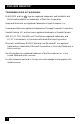
FCC/IC STATEMENTS FEDERAL COMMUNICATIONS COMMISSION AND INDUSTRY CANADA RADIO-FREQUENCY INTERFERENCE STATEMENTS This equipment generates, uses, and can radiate radio-frequency energy, and if not installed and used properly, that is, in strict accordance with the manufacturer’s instructions, may cause interference to radio communication.
MULTI-HEAD SERVSWITCH™ EUROPEAN UNION DECLARATION OF CONFORMITY This equipment has been tested and found to comply with the limits for a class B computing device in accordance with the specifications in the European standard EN55022. These limits are designed to provide reasonable protection against harmful interference.
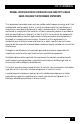
NOM STATEMENT NORMAS OFICIALES MEXICANAS (NOM) ELECTRICAL SAFETY STATEMENT INSTRUCCIONES DE SEGURIDAD 1. Todas las instrucciones de seguridad y operación deberán ser leídas antes de que el aparato eléctrico sea operado. 2. Las instrucciones de seguridad y operación deberán ser guardadas para referencia futura. 3. Todas las advertencias en el aparato eléctrico y en sus instrucciones de operación deben ser respetadas. 4. Todas las instrucciones de operación y uso deben ser seguidas. 5.
MULTI-HEAD SERVSWITCH™ 12. Precaución debe ser tomada de tal manera que la tierra fisica y la polarización del equipo no sea eliminada. 13. Los cables de la fuente de poder deben ser guiados de tal manera que no sean pisados ni pellizcados por objetos colocados sobre o contra ellos, poniendo particular atención a los contactos y receptáculos donde salen del aparato. 14. El equipo eléctrico debe ser limpiado únicamente de acuerdo a las recomendaciones del fabricante. 15.
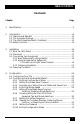
TABLE OF CONTENTS Contents Chapter Page 1. Specifications ............................................................................................. 9 2. Introduction ............................................................................................. 2.1 Features and Benefits ....................................................................... 2.2 The Complete Package ..................................................................... 2.3 The Multi-Head ServSwitch Illustrated ........
MULTI-HEAD SERVSWITCH™ Contents (continued) Chapter 5. 6. Page Operation ................................................................................................. 5.1 Power Status ..................................................................................... 5.2 The Front-Panel Pushbutton and the Remote-Control Module ... 5.3 The Status Display ........................................................................... 5.4 Things to Keep in Mind About the Keyboards and Mice .............
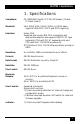
CHAPTER 1: Specifications 1.
MULTI-HEAD SERVSWITCH™ Connectors: All rear-mounted: (1) Multipurpose DB15 female (see Section A.
CHAPTER 1: Specifications Power — Either: • 5 VDC at up to 500 mA from the keyboard interfaces of the attached computers, or • From the optional power supply PS649 (not included): Input: 100 to 240 VAC at 50 to 60 Hz from utilitypower (mains) outlet, through detachable power cord and IEC 320 male inlet, to external transformer; Output: 5 VDC at up to 1 A; Consumption: 5 watts maximum Size: 4.1"H x 10.3"W x 5.9"D (10.4 x 26.2 x 15 cm) Weight: 5.5 lb. (2.
MULTI-HEAD SERVSWITCH™ 2. Introduction The Multi-Head ServSwitch™ is a high-performance keyboard-, mouse-, and monitor-sharing device that supports a wide range of IBM® PC compatible hardware with multiple video outputs.
CHAPTER 2: Introduction • Two Switches can be synchronized to handle computers with up to eight video outputs. • Automatically restores keyboard and mouse states when channel is changed. • CPUs can have either PS/2 or PC/AT® keyboard ports and either PS/2 or RS-232 mouse ports. • Supports keyboard modes 1, 2, and 3, as well as both “prompt” and “stream” mouse modes, for maximum compatibility. • Support for Microsoft® IntelliMouse™ and many other “wheel mice.
MULTI-HEAD SERVSWITCH™ 2.3 The Multi-Head ServSwitch Illustrated Display shows status and mouse/keyboard data activity Button for changing channels and entering configuration mode Figure 2-1. The Multi-Head ServSwitch’s front panel.
CHAPTER 2: Introduction 2.4 Safety Concerns As you prepare to install the Multi-Head ServSwitch, please keep these things in mind: • The Switch is for use in dry, oil-free indoor environments only. • Do not attempt to fix the Switch yourself. • Follow all warnings and instructions marked on the Wizard, its optional power supply, and any other accessories.
MULTI-HEAD SERVSWITCH™ 3. Installation 3.1 What You Will Need You’ll need these things to be in place before you can install your Multi-Head ServSwitch: • Cables to connect the Multi-Head ServSwitch to the keyboard, mouse, and video ports of each of your computers. (You don’t need to connect mouse cabling to a CPU if you’re not using a mouse with that CPU.) You’ll need adapters to connect the Switch to the keyboard and mouse ports of PC/AT style computers.
CHAPTER 3: Installation • A suitable mouse driver for your PCs. Supported types are: – PS/2 or RS-232 two-button mouse driver by any manufacturer. – Microsoft mouse drivers, including those for the IntelliMouse. (You might be able to user other drivers with IntelliMouse compatible data formats, but these might not work—trial-and-error testing might be necessary.) – Logitech mouse drivers, including those for two-button, three-button, and wheel mice. 3.
MULTI-HEAD SERVSWITCH™ 3.3.1 BASIC SYSTEMS WITH A SINGLE SWITCH Make sure that the Multi-Head ServSwitch is unplugged and powered down. If possible, turn off and unplug all of the devices that you want to attach to it. (If you have to “hot-plug” any powered computers into the Switch, see Section 5.8.) Connect your user equipment (keyboard, PS/2 mouse, and monitors) to the appropriate “control port” connectors on the Switch’s rear panel.
CHAPTER 3: Installation 3.3.2 SYNCHRONIZED SWITCH SYSTEMS FOR CPUS WITH UP TO EIGHT VIDEO OUTPUTS Some CPUs and video cards can support a very large number of simultaneous video outputs. CPUs with more than four video heads can’t be supported by a single Multi-Head ServSwitch. But two Switches can be “synchronized” to handle CPUs with as many as eight video heads.
MULTI-HEAD SERVSWITCH™ Connect each computer CPU to the synchronized Switch system. First run cabling from the CPU’s keyboard port, mouse port, and first four video outputs to the matching connectors in one of the master Switch’s “CPU ports.” This cabling can be either separate male-to-male keyboard-, mouse-, and video-extension cables, or our three-in-one Premium KVM CPU Cable. If you need to run farther than 100 ft.
CHAPTER 3: Installation 3.3.3 CABLES AND ADAPTERS Attaching a CPU’s 6-pin mini-DIN keyboard and mouse ports and its two or more HD15 video ports to the Multi-Head ServSwitch will require extension cables. You can use HD15 male-to-male VGA-extension cables (product code EVNPS05-MM) to make the video-port connections; one of these cables will be required for each videoport connection after the first.
MULTI-HEAD SERVSWITCH™ 6-Pin mini-DIN 6-Pin mini-DIN HD15 10" (25.4 cm) 9" (22.9 cm) Cross-section: Central video strand Keyboard and mouse strands molded to sides Figure 3-3. The Premium KVM cables. To connect computers with serial mouse ports and/or PC/AT style keyboard ports, you’ll need adapters like those shown in Figure 3-4. Refer to the Appendix.
CHAPTER 3: Installation 3.4 Powering the Switch Once you’ve installed your Multi-Head ServSwitch system and attached your equipment to it, you need to apply power to each Switch. You can do this in either of two ways. Most basic systems should be able to get the power they need from the attached CPUs.
MULTI-HEAD SERVSWITCH™ 4. Configuration To configure your Multi-Head ServSwitch system, you’ll need to configure first the attached PCs, as directed in Section 4.1, then the Switch itself, as directed in the rest of this chapter. IMPORTANT NOTE Throughout the rest of this manual, the [Enter] designation refers to the main “enter” or “carriage-return” key (often labeled “↵”) on the main section of the keyboard.
CHAPTER 4: Configuration 4.2 Configuring the Multi-Head ServSwitch The Multi-Head ServSwitch comes from the factory preset to default configuration settings which are suitable for most applications. If you need to set the Switch differently, you can access its “configuration mode” to do so; once you do, the new settings are stored in the Multi-Head ServSwitch’s EEPROM memory and are retained when the Switch is powered OFF. 4.2.
MULTI-HEAD SERVSWITCH™ 4.2.2 SETTING THE SCREEN-SAVER TIMEOUT The Multi-Head ServSwitch has a programmable screen-saver function which will blank the displays on the shared monitors after a certain time elapses with no activity on the shared keyboard or mouse. The Switch’s front-panel display will flash while the Switch is in screen-saver mode. To restore the blanked monitor display, just type at the keyboard or move the mouse.
CHAPTER 4: Configuration 4.2.3 AUTOSCANNING: SETTING THE SCAN MODE AND PAUSE TIME The Multi-Head ServSwitch begins autoscanning its CPU channels (that is, briefly displaying each channel’s video feeds in turn) when you type in the hotkey sequence followed by the letter “A” (see Section 5.5). By default, the Switch only scans those channels that have a powered-up computer connected to them. But if you need the Switch to scan all of its channels, you can send it the [L][2] or [L][4] command.
MULTI-HEAD SERVSWITCH™ 4.2.4 ENFORCING MOUSE SPEED In its factory-default state, the Multi-Head ServSwitch allows each CPU to handle mouse communication any way the CPU wants to. However, some CPUs with particular rare combinations of operating systems, mice, and mouse drivers can be abnormally sensitive to small timing changes in mouse communication. These CPUs can react badly to the presence of the Switch, making persistent timing errors that cause the mouse to seem slow or sluggish.
CHAPTER 4: Configuration 4.2.5 SETTING MOUSE-MODE REPORTING AND ENABLING/DISABLING MOUSE SWITCHING In the Multi-Head ServSwitch’s factory-default state, you can use a three-button PS/2 mouse or an IntelliMouse to cycle through the Switch’s CPU channels. To switch to the next channel, simply hold down the center or “wheel” button on the mouse, then press its left button.
MULTI-HEAD SERVSWITCH™ 4.2.6 CHOOSING ACTIVE PORTS OR ALL PORTS FOR KEYBOARD-TAB AND MOUSE SWITCHING In the Multi-Head ServSwitch’s factory-default state, when you “cycle through” the CPU ports on the Switch by pressing {Hotkeys} + [Tab] or when you switch to the next or previous channel with your mouse, the Switch stops at every channel. It does this even if the device attached to a particular channel is off or not outputting video, or even if there isn’t any device attached to that channel.
CHAPTER 4: Configuration 4.2.7 SETTING THE HOTKEY SEQUENCE You can access many of the Multi-Head ServSwitch’s main functions (such as CPUchannel selection, autoscanning, and locking) by sending commands from the shared keyboard. Each command must start with a “hotkey sequence” (series of keystrokes) that alerts the Switch to interpret the keyboard data that follows it as a command. The default hotkey sequence is [Ctrl] and [Alt] pressed simultaneously.
MULTI-HEAD SERVSWITCH™ 4.2.8 VIEWING THE FIRMWARE REVISION, RESTORING MOUSE FUNCTION, OR RESETTING TO FACTORY DEFAULTS For technical-support purposes, it might be necessary to find out the firmwarerelease version of the control software in your Multi-Head ServSwitch.
CHAPTER 4: Configuration 4.2.9 SETTING THE PASSWORD There are many situations where access to corporate file servers or sensitive information needs to be controlled. In such circumstances, the Multi-Head ServSwitch can be locked away in a room or secure cabinet and controlled remotely. In this mode, you can type the hotkey sequence followed by the number “0” (zero) at the shared keyboard of the active control port in order to “lock” the Switch.
MULTI-HEAD SERVSWITCH™ 5. Operation This chapter explains how to operate the Multi-Head ServSwitch. Please read this chapter carefully before starting to use the Switch; also make sure you have read the important note at the start of Chapter 4. 5.1 Power Status At power-up, the Multi-Head ServSwitch will try to select CPU channel #1 unless (a) a password has been set or (b) the Switch isn’t getting enough power to operate properly.
CHAPTER 5: Operation 5.2 The Front-Panel Pushbutton and the Remote-Control Module You can use the Multi-Head ServSwitch’s front-panel pushbutton to select which CPU channel (CPU port) is currently controlled by the active control port. Press the key once during normal operation to select the next CPU channel in sequence (for example, to select channel 4 if channel 3 is currently selected); press the key repeatedly to manually cycle through the channels.
MULTI-HEAD SERVSWITCH™ 5.3 The Status Display The Multi-Head ServSwitch’s front-panel 7-segment status display usually shows the number of the currently selected computer channel, while the dot LED alongside it flashes in response to data from the shared keyboard or mouse (see the top illustration in Figure 5-2).
CHAPTER 5: Operation 5.4 Things to Keep in Mind About the Keyboards and Mice CPU bootup sequence: When your computer CPUs are powered on, they communicate with any attached keyboards and mice and load the setup parameters required by their particular operating systems. It’s necessary for the Multi-Head ServSwitch to be attached and powered on during this sequence so that it can give the CPUs the required responses and keep track of all the modes and settings requested by each of the connected CPUs.
MULTI-HEAD SERVSWITCH™ 5.5 Keyboard Control: Hotkey Commands You can control many functions on the Multi-Head ServSwitch—such as CPUchannel selection, autoscanning, or locking—from the keyboard, using commands triggered with the Switch’s currently selected hotkey combination. All of the hotkey-control commands are invoked by holding down the one or two hotkeys and then pressing a command key.
CHAPTER 5: Operation • Use {Hotkeys} + [L] to lock the Switch (disable its shared keyboard and mouse and select nonexistent “channel zero” in order to shut off the video output from the Switch to the shared monitors). If a password has not been set (see Section 4.2.9), the Switch behaves exactly as if you had entered {Hotkeys} + [0] (see above).
MULTI-HEAD SERVSWITCH™ 5.6 Mouse Control Yet another convenient way to select CPU channels on the Multi-Head ServSwitch is through a three-button mouse, if this feature is enabled (see Section 4.2.6). As shown in Figure 5-3 (button to hold down is black, button to click is gray): • To switch to the next channel, hold down the central mouse button or “wheel” button, then click on the left-hand mouse button.
CHAPTER 5: Operation 5.7 Re-Enabling a Disconnected PS/2 Mouse If you accidentally disconnect the shared PS/2 mouse from the Multi-Head ServSwitch while the Switch is operating, the mouse will not work correctly when you plug it back in. To avoid having to reboot the entire system in this situation, the Switch has an automatic mouse-recovery system. With the PS/2 mouse disconnected, change the channel using the Switch’s front-panel pushbutton or the keyboard hotkeys.
MULTI-HEAD SERVSWITCH™ Standard PS/2 mouse data uses a different data format than IntelliMouse data, so two reset functions are provided on the Multi-Head ServSwitch. The type of data format expected by the CPU depends upon the driver and the type of mouse that was connected when the driver was booted.
CHAPTER 5: Operation 5.9 RS-232 Control There is yet one more way to select channels on the Multi-Head ServSwitch: through its RS-232 serial port. (This is a proprietarily pinned DB15 connector; see Section A.3 of the Appendix for more information.) This connector serves more often as the attachment point for the Switch’s optional Remote-Control Module, but by using an adapter you can connect a different RS-232 device to it.
MULTI-HEAD SERVSWITCH™ 5.11 Upgrading the Switch’s Firmware Because the Multi-Head ServSwitch stores most of its firmware (its “operating system,” if you will) in flash memory, the firmware is upgradable. To fix bugs in existing firmware, or to add features to your Switch, Black Box Technical Support might sometimes recommend that you upgrade the Switch’s firmware if a newer revision is available. (Follow the procedure described in Section 4.2.
CHAPTER 5: Operation The Multi-Head ServSwitch’s front-panel 7-segment display should now show a lowercase “u” to indicate that the Switch is ready to be upgraded: 5. Run the SSWxyz.EXE firmware-upgrade program that you downloaded in step 1. Follow the directions that appear on the host PC’s screen to transfer the new firmware to the Switch. The Switch’s 7-segment display will change to show an uppercase “U” and its dot will flash to show that the Switch’s receiving data from the PC: 6.
MULTI-HEAD SERVSWITCH™ 6. Troubleshooting 6.1 Things to Try This section suggests possible answers for a number of problems that people sometimes encounter when trying to operate the Multi-Head ServSwitch. If the suggested actions don’t solve your problem, or if you don’t see a listing for the type of trouble you’re having, contact Black Box Technical Support as described in Section 6.2. Problem: Poor video quality with smearing, fuzziness, or rippling.
CHAPTER 6: Troubleshooting Problem: Your keyboard does not function or functions only intermittently. The Num Lock LED does not always light when the Num Lock key is pressed. Possible Solution: Some older keyboards were designed for use with specific computers and are not truly PC/AT or PS/2 compatible. These are not common, but if you’re having problems like this and you’re using an old keyboard, try a newer keyboard. Problem: Just using your mouse normally causes the CPU channel to change unexpectedly.
MULTI-HEAD SERVSWITCH™ Problem: Compaq MX11800 model integrated keyboard and mouse only: The mouse consistently fails to boot when the Switch is connected to PCs running Windows NT 4.0 through their PS/2 style mouse ports. Possible Solutions: There are three possible solutions to this problem: 1. Use a different type of mouse. 2. Connect the Switch to your NT 4.0 PCs through adapters and their serial ports rather than through their PS/2 ports. 3.
APPENDIX: Cable Guidelines Appendix: Cable Guidelines IMPORTANT NOTE The maximum supported cable lengths vary widely between devices and cables. It might be possible to use cables that are longer than those specified in this Appendix with certain computers and peripherals, but this can’t be guaranteed. If you have problems, try using shorter cables. A.
MULTI-HEAD SERVSWITCH™ Keyboard- and PS/2 mouse-extension cabling: 6-pin mini-DIN male to 6-pin miniDIN male with all lines connected straight through (1 to 1, 2 to 2, etc.). If the PC has a 5-pin DIN PC/AT style keyboard connector, you will need a PS/2 to PC/AT keyboard adapter, 6-pin mini-DIN female to 5-pin DIN male (FA212). If you’re not using the Switch’s optional power supply, the keyboard- and mouseextension cables should be no longer than 16 ft. (5 m) in any situation.
APPENDIX: Cable Guidelines 6-pin mini-DIN attaches to Switch or cable from Switch DB9 attaches to PC’s serial port or cable to PC’s serial port KDAT RLSD (DCD) N/C TD RD SGND TD (-12V) +5V DTR KCLK SGND -12V DSR RTS Male 5 N/C CTS N/C RI 1 6 5 Male 4 3 1 6 2 Female 6 5 Female 1 5 4 9 3 2 1 9 6 Figure A-1. The RS-232 mouse adapter’s pinout.
MULTI-HEAD SERVSWITCH™ A.3 Cabling Attached to the OPTIONS Port The DB15 connector labeled “OPTIONS” on the back of the Multi-Head ServSwitch is a proprietarily pinned port using RS-232-type signaling. You can connect any of these devices to it: • The Switch’s optional Remote-Control Module (RCM, see Section 5.2); • An RS-232 device for serially controlled channel switching (see Section 5.9); • Another Switch, to create a synchronized system for CPUs with as many as eight video outputs (see Section 3.3.
APPENDIX: Cable Guidelines DB15 male attaches to master Switch DB15 male attaches to secondary Switch RD TD RD SGND SGND Male 1 8 9 15 Male 1 8 9 15 Figure A-2. The synchronization cable. DB9 female attaches to PC DB15 male attaches to Switch TD RD RD TD DTR DSR CTS SGND SGND 5 Female 1 9 6 Male 1 9 8 15 Figure A-3. The firmware-upgrade cable KV6SER.
MULTI-HEAD SERVSWITCH™ DISCLAIMERS While every precaution has been taken in the preparation of this manual, neither the manufacturer nor its authorized agents assume any responsibility for errors or omissions. Nor do they assume any liability for damages resulting from the use of the information contained herein. They reserve the right to change the specifications, functions, or circuitry of the product without notice.
NOTES
NOTES