
User's Manual

724-746-5500 | blackbox.com
Chapter 2: Overview
724-746-5500 | blackbox.com
Page 11
2.6 Hardware Description, Multi Head Versions (KV3204A, KV3304A, KV3404A)
2.6.1 Front Panel
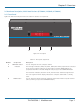
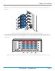
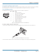
Figure 2-4 shows the front panel of the unit. Table 2-3 describes its components:
Figure 2-4. Front panel.
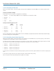
Table 2-3. Front panel components.
Number Component Description
1 COMPUTER button Press to change to the next computer channel.
2 Indicators The four upper indicators (KVM, SPK, USB1, USB2) show which peripherals are switched
to the current computer channel or (as you begin pressing the MODE button) the
peripherals that will be switched during the next press(es) of the COMPUTER button.
The four lower indicators, labeled V1 to V4, show the video channels being switched.
The seven-segment numeric display indicates the computer channel that is currently
active.
3 MODE button Press to determine which peripherals should be switched to another computer channel
(will occur when you press the COMPUTER button).
COMPUTER
KVM
V1
SPK
V2
USB1
V3
USB2
V4
MODE
1
2 3